
Related Manuals for Lightware MMX4x2 Series


Summary of Contents for Lightware MMX4x2 Series
- Page 1 User’s Manual MMX4x2-HDMI MMX4x2-HT200 MMX4x2-HDMI-USB20-L Standalone Multimedia Matrix Switcher v3.2 22-03-2022 ...
- Page 2 MMX4x2 series – User's Manual Important Safety Instructions Waste Electrical & Electronic Equipment Common Safety Symbols WEEE Class II apparatus construction. Symbol Description This marking shown on the product or its literature The equipment should be operated only from the power source indicates that it should not be disposed with other indicated on the product.
- Page 3 The following symbols and markings are used in the document: All presented functions refer to the indicated products. The descriptions Lightware Visual Engineering supports green technologies and eco- have been made while testing these functions in accordance with the friendly mentality. Thus this document is made primarily for digital...
-
Page 4: Table Of Contents
4.16.2. Advanced EDID Management ............36 5.10.6. Event Creating - Example .............. 63 3. INSTALLATION ................21 5.11. Settings Menu ................64 5. SOFTWARE CONTROL - LIGHTWARE DEVICE CONTROLLER ..37 3.1. Mounting Options ...............22 5.11.1. Status ..................... 64 5.1. Install and Update ..............38 3.1.1. 1U High Rack Shelf ................22 5.11.2. Network .................. - Page 5 MMX4x2 series – User's Manual 6. LW2 PROGRAMMERS' REFERENCE ..........70 7. LW3 PROGRAMMERS’ REFERENCE ..........82 7.6.14. Muting an Output Port ..............92 7.6.15. Unmuting an Output Port .............. 92 6.1. Protocol Description ..............71 7.1. Overview ..................83 7.6.16. Locking an Output Port ..............92 6.2. Instructions for the Terminal Application Usage ....71...
- Page 6 MMX4x2 series – User's Manual 7.9.5. Setting an Action by Specifying a Direct Path ......106 7.15.6. Sending a Put Message .............. 116 7.20.5. Querying the Last Received CEC Message ........ 126 7.9.6. Setting an Action by Linking Another Action ....... 106 7.16. TCP Message Recognizer ............117...
- Page 7 MMX4x2 series – User's Manual 8.6.3. Check For New LDU2 Version ............146 8.6.4. Device Info ..................146 8.6.5. Update .................... 147 8.6.6. Restore ................... 147 8.6.7. Package Options ................148 8.6.8. Complex Examples ................ 148 8.6.9. Exit Codes ..................149 8.7. If the Update is not successful ..........150 9.
-
Page 8: Introduction
1. Introduction MMX4x2 series – User's Manual I ntroduction Thank you for choosing Lightware’s MMX4x2 series device. In the first chapter we would like to introduce the device, highlighting the most important features in the coming sections. ç Description ç Compatible Devices ç... -
Page 9: Description
MMX4x2 series – User's Manual 1.1. Description 1.2. Compatible Devices MMX4x2 series device is a unique mini size matrix switcher. The HT200 model has three HDMI inputs and The MMX4x2-HT200 matrix is compatible with other Lightware TPS transmitters, matrix TPS and TPS2 one HDBaseT compatible TPS input port. -
Page 10: Optional Accessories
1. Introduction MMX4x2 series – User's Manual 1.4. Optional Accessories 1.5. Typical Applications The following not-supplied accessories can be purchased and used with the device; please contact Standalone Application - MMX4x2-HDMI-USB20-L sales@lightware.com. RAP-B511 Room TBP6 Button Panel Rack shelf... - Page 11 1. Introduction MMX4x2 series – User's Manual Standalone Application - MMX4x2-HDMI Standalone Application - MMX4x2-HT200 Applied firmware package: v1.6.0b19 | LDC software: v2.5.13b5...
-
Page 12: Features
Event manager Actions. The miniweb can be displayed in a mobile device, too. A batch of LW3 commands (salvo) can be run by the Lightware device either by a previously stored macro or by sending a file to the device with the desired commands. -
Page 13: Feature Availability
1. Introduction MMX4x2 series – User's Manual 1.6.2. Feature Availability Advanced Control Pack Advanced Control Pack v3 Basic features (from FW package v1.3.1) (from FW package v1.6.0b19) RS-232 RS-232 11 0100 1 11 0100 1 MMX4x2-HDMI ... -
Page 14: Product Overview
2. Product Overview MMX4x2 series – User's Manual P roduct Overview The following sections are about the physical structure of the device, input/output ports and connectors, buttons and status LEDs. ç MMX4x2-HT200 ç MMX4x2-HDMI ç MMX4x2-HDMI-USB20-L ç... -
Page 15: Mmx4X2-Ht200
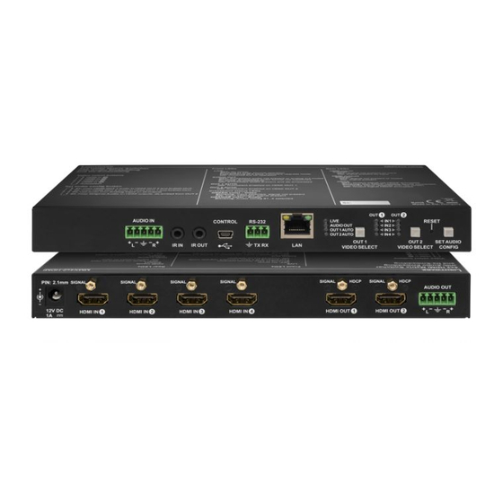
2. Product Overview MMX4x2 series – User's Manual 2.1. MMX4x2-HT200 Rear View Front View 5 6 7 8 9 12V DC 1A input port Local power in; connect the output of the supplied 12V DC power Audio input port 5-pole Phoenix connector for balanced analog audio. -
Page 16: Mmx4X2-Hdmi
2. Product Overview MMX4x2 series – User's Manual 2.2. MMX4x2-HDMI Rear View Front View 5 6 7 8 9 12V DC 1A input port Local power in; connect the output of the supplied 12V DC power Audio input port 5-pole Phoenix connector for balanced analog audio. -
Page 17: Mmx4X2-Hdmi-Usb20-L
2. Product Overview MMX4x2 series – User's Manual 2.3. MMX4x2-HDMI-USB20-L Rear View Front View RS-232 (#2) 3-pole Phoenix connector for controlling the device with LDC, third- party control systems, or third-party device control. Pin assignment can be found in the RS-232 Connector section. -
Page 18: Front Panel Leds
2. Product Overview MMX4x2 series – User's Manual 2.4. Front Panel LEDs 2.5. Rear Panel LEDs Status LEDs HDMI input LEDs LIVE LED Signal is not present on input. The device is not powered. Signal is present on input. -
Page 19: Front Panel Buttons
2. Product Overview MMX4x2 series – User's Manual 2.6. Front Panel Buttons Config #2 2.6.1. OUT 1 and OUT 2 Video Select Buttons Copy HDMI OUT 2 audio to HDMI OUT 1 and Analog Audio Out. A1 (HDMI OUT 1,... -
Page 20: Enable Dhcp (Dynamic) Ip Address
The device has a static IP address as a factory default setting. If this setting does not Lightware Device Updater (LDU) software. Do not use this option with LDU2 software. fit the circumstances during install or usage, DHCP can be enabled from the front panel: RESET Step 1. -
Page 21: Installation
3. Installation MMX4x2 series – User's Manual Installation The chapter is about the installation of the device and connecting to other appliances, presenting also the mounting options and further assembly steps. ç Mounting Options ç Electrical Connections ç... -
Page 22: Mounting Options
The UD-kit double makes it easy to mount a single matrix on any flat surface (e.g. furniture). To mount the matrix, Lightware supplies optional accessories for different usage. There are two kinds of mounting kits with a similar fixing method. The receiver has two mounting holes with inner thread on the bottom side;... -
Page 23: Electrical Connections
Wiring of TPS and LAN Cables and ground to the source and connect – to the ground. Lightware recommends the termination of LAN cables on the basis of TIA/EIA T 568 A or TIA/EIA T 568 B standards. Pin nr. -
Page 24: Usb Connectors
3. Installation MMX4x2 series – User's Manual 3.2.5. USB Connectors 3.2.8. GPIO - General Purpose Input/Output Ports The matrix provides a standard USB mini B-type connector on the front panel for device control DIFFERENCE: This section refers to MMX4x2-HDMI-USB20-L model only. -
Page 25: Connecting Steps
Connect the IR detector to the IR IN port of the matrix. Optionally for Infrared extension: Optionally connect a device to the GPIO port (e.g. Lightware’s TBP6-EU-K button panel for room GPIO - Connect the IR emitter to the IR OUT port of the device. -
Page 26: Device Concept
4. Device Concept MMX4x2 series – User's Manual Device Concept The following chapter describes the features of the device with a few real-life examples. ç Compact Size Matrix Concept ç Video Interface ç Consumer Electronics Control (CEC) Interface ç... -
Page 27: Compact Size Matrix Concept
4.1. Compact Size Matrix Concept 4.2. Video Interface MMX4x2 series device is a multi-functional audio/video matrix switcher with four inputs and two outputs The following figure describes the port diagram of the MMX4x2-HT200 matrix: designed into a compact size frame. The HT200 model is built with HDBaseT (TPS) technology. -
Page 28: Consumer Electronics Control (Cec) Interface
All related settings are available in the LDC software, see the details in the Crosspoint Menu section. analog audio input port is able to be embedded into the HDMI outputs. 4.4.2. Audio Output Modes The MMX4x2 series matrix can transmit two types of audio: ▪ Embedded (HDMI) and ▪ Analog balanced stereo audio. -
Page 29: The Autoselect Feature
Blu-ray player (via a TPS transmitter) I1 (TPS IN 1) Port with priority priority 1 has a 1 is selected Priorities can be set in Lightware Device Controller software, see related settings in the HDMI Video Output valid signal? section. Port with... -
Page 30: Usb Interface
The device can be controlled over front panel USB port (mini B-type connector). This interface supports only connected to the USB A-type ports. The user can select to switch the USB peripherals to the PC or to the LW3 protocol. The interface can be used to establish a connection to Lightware Device Controller software. laptop. -
Page 31: Tcp Recognizer
The Event Manager feature means that the device can sense changes on its ports and is able to react according to the pre-defined settings. Lightware Device Controller contains a user-friendly software tool and The feature is almost the same as in case of the RS-232, but for the network interface: the incoming TCP allows creating Events by defining a Condition and an Action. -
Page 32: Basic It Security
You can set all affected TCP/IP ports individually to enable or disable. LPPF1 LPPF2 HDBaseT Long reach Auto The IP Port Block feature is an additional protection for the Cleartext login. There are TCP/IP ports in Lightware LPPF1 LPPF1 LPPF1 LPPF1 LPPF1 LPPF1 devices that are not protected by the login, so you can disable them if necessary. -
Page 33: Serial Interface
4. Device Concept MMX4x2 series – User's Manual 4.11. RS-232 Serial Interface Command Injection Mode In this mode, the matrix works as a TCP/IP <-> RS-232 bidirectional converter. The TCP/IP data signal is 4.11.1. Technical Background converted to RS-232 data and vice versa. TCP/IP port numbers are defined for the serial ports (TPS and ATTENTION! Only MMX4x2-HT200 model has TPS serial link port. -
Page 34: Recognizer
This feature allows the LW device to be controlled over HTTP. In this case, a batch of commands is sent ('Admin') on the P1 port to the VC codec. over HTTP to the Lightware device for processing. Save the LW3 commands into a file, post it to the For more information about setting the events, see Event Manager section. -
Page 35: Ir Interface
Advanced IR functionality DIFFERENCE: The features mentioned below are available from firmware v1.3.1. MMX4x2 series can send Little-endian pronto hex IR codes on its IR output port as follows: With Event Manager (see more details in the Event Manager section) -
Page 36: Gpio Interface
GPIO Options - Example The device (configuration) cloning of MMX4x2 series matrix is a simple method that eliminates the need to repeatedly configure multiple devices to have identical (non-factory) settings. If the devices are installed in the same type of system multiple times, then it is enough to set up only one device to fit the user’s needs and... -
Page 37: Software Control - Lightware Device Controller
S oftware Control - Lightware Device Controller The device can be controlled by a computer through Ethernet and RS-232 interfaces by the Lightware Device Controller (LDC). The software can be installed on a Windows PC or macOS. The application and the User’s Manual can be downloaded from www.lightware.com. -
Page 38: Install And Update
LightwareDeviceController -c <COM_port>:<Baud> Format: The Device Discovery window appears automatically, and Example: LightwareDeviceController -c COM1:57600 the program checks the available updates on Lightware’s website and opens the update window if the LDC found Adjusting the Zoom updates. The window can be zoomed to a specific value to fit to the resolution of the desktop (higher/lower). '1' is the The current and the update version number can be seen default value (100%). -
Page 39: Establishing The Connection
Step 2. Run the controller software; the Device discovery window appears automatically. There are three tabs as you can expand the list of Favorite devices with any Lightware device that is connected via Ethernet in any for the different types of interfaces; Ethernet, Serial and USB. -
Page 40: Serial Tab
5. Software Control - Lightware Device Controller MMX4x2 series – User's Manual 5.3.4. Further Tools Highlighting the Device DIFFERENCE: This feature is available only from FW package v1.6.0b19. The Tools menu contains the following options: Log Viewer: The tool can be used for reviewing log files that have been saved previously. -
Page 41: Crosspoint Menu
5. Software Control - Lightware Device Controller MMX4x2 series – User's Manual 5.4. Crosspoint Menu Video input ports Each tile represents a video input port (TPS Video Input HDMI Video Input). The tile below the port shows the current crosspoint setting; if the... -
Page 42: Presets Tab
5. Software Control - Lightware Device Controller MMX4x2 series – User's Manual 5.4.2. Presets Tab 5.4.3. Port Tiles The colors of the port tiles and the displayed icons represent different states and information: Port name Port icon HDMI OUT1... -
Page 43: Port Properties Windows
5. Software Control - Lightware Device Controller MMX4x2 series – User's Manual 5.5. Port Properties Windows 5.5.2. HDMI Video Input Clicking on the HDMI video input port icon opens the Port properties window. The most important information Clicking on the port tile opens the Port properties window. This section shows the available settings and and settings are available from the panel. -
Page 44: Hdmi Video Output
5. Software Control - Lightware Device Controller MMX4x2 series – User's Manual 5.5.3. HDMI Video Output Available settings and tools: Mute/unmute the port; ▪ Lock/unlock the port; ▪ Autoselect settings (see below) ▪ Signal type: Auto / DVI / HDMI - The outgoing signal format can be selected from a drop-down menu;... -
Page 45: Digital Audio Input
5. Software Control - Lightware Device Controller MMX4x2 series – User's Manual 5.5.4. Digital Audio Input 5.5.5. Analog Audio Input A1 and A2 inputs are logical audio ports which are the audio channels of the selected HDMI input ports. -
Page 46: Digital Audio Output
5. Software Control - Lightware Device Controller MMX4x2 series – User's Manual 5.5.6. Digital Audio Output The port properties windows of the video and audio outputs are mirrored. For example the same window will be opened when you select the HDMI OUT1 on the Video or the Audio sections. The available settings can... -
Page 47: Cec Tool
5. Software Control - Lightware Device Controller MMX4x2 series – User's Manual 5.6. CEC Tool Drop-down Containing the basic CEC commands, most of them are displayed on the command list graphical interface, too (on the left side). Click on the Send button to send the The device is able to send and receive Consumer Electronics Control (CEC) commands. -
Page 48: Diagnostic Tools
Clock Source Lightware’s Frame Detector function works like a signal analyzer and makes it possible to determine the exact video format that is present on the port, thus helps to identify many problems. E.g. actual timing ▪... -
Page 49: Cablediagnostics
5. Software Control - Lightware Device Controller MMX4x2 series – User's Manual 5.7.3. Cable Diagnostics Table and Chart Views Cable diagnostics can be displayed in advanced modes as well. Two ways are available: table view and chart DIFFERENCE: This tool is available for the MMX4x2-HT200 model only. -
Page 50: Edid Menu
5. Software Control - Lightware Device Controller MMX4x2 series – User's Manual 5.8. EDID Menu 5.8.1. EDID Operations Advanced EDID Management can be accessed by selecting the EDID menu. There are two panels: the left Changing Emulated EDID one contains Source EDIDs, the right one contains Destination places where the EDIDs can be emulated or Step 1. -
Page 51: Edid Summary Window
Since the Advanced EDID Editor mentioned above needs more complex knowledge about Create EDID, Lightware introduced a wizard-like interface for fast and easy EDID creation. With Easy 5.8.3. Editing an EDID EDID Creator, it is possible to create custom EDIDs in four simple steps. For more details about EDID Editor, please visit our website (www.lightware.com) and download the... -
Page 52: Control Menu
5. Software Control - Lightware Device Controller MMX4x2 series – User's Manual 5.9. Control Menu RS-232 Message Sending The message in the field can be sent out via the 5.9.1. RS-232 current RS-232 port. Response cannot be seen in DIFFERENCE: MMX4x2-HDMI-USB20-L model is assembled with two local RS-232 ports. -
Page 53: Ethernet
5.9.2. Ethernet HTTP Clients (HTTP Post and Put Message Sending) ATTENTION! This feature means posting or putting HTTP messages from the Lightware device to another DIFFERENCE: MMX4x2-HDMI-USB20-L model has three Ethernet ports. TPS port can be found on device. Encrypted transmission (HTTPS) is not supported. - Page 54 Encrypted transmission (HTTPS) is not supported. TCP Recognizer section. #tcprecognizer #message In this case, a batch of commands can be sent over HTTP to the Lightware device for processing. Post the commands to the <IP_address>/protocol.lw3 address and the commands are processed immediately and sequentially. #http Control commands can be sent to the Lightware device, but it is not suitable for querying a parameter/status, since the LW3 responses are not sent back to the sender.
-
Page 55: Gpio
5. Software Control - Lightware Device Controller MMX4x2 series – User's Manual 5.9.3. GPIO 5.9.4. Infra DIFFERENCE: This section refers to the MMX4x2-HDMI-USB20-L model only. ATTENTION! The device has no built-in Infrared receiver and transmitter. For the complete usage attach an IR emitter unit to the IR OUT and an IR detector unit to the IR IN connectors. - Page 56 5. Software Control - Lightware Device Controller MMX4x2 series – User's Manual Ports Description Function The user can set the name and command injection port for each source and destination. For more details, Code number. about IR interface see the Messaging Options section.
-
Page 57: Macros
5. Software Control - Lightware Device Controller MMX4x2 series – User's Manual 5.9.5. Macros DEFINITION: Macro is a batch of pre-defined commands stored in the device. #macro You can create your custom macros in a file, upload them to the device and run at any time. The number of the macros depends on the device type, for example MMX4x2 can handle up to 50 macros. -
Page 58: Variables
5. Software Control - Lightware Device Controller MMX4x2 series – User's Manual 5.9.6. Variables Value Section You can set the value of the variable by the field. The type of the variable is determined automatically based A brand new area is opened by implementing the variables. You can create custom variables in number on its value (numeric/string). -
Page 59: Usbswitch
5. Software Control - Lightware Device Controller MMX4x2 series – User's Manual 5.9.7. USBSwitch Scan and Store This tool can be used to get the value (or a part) of an LW3 property. The defined path will be checked DIFFERENCE: This section refers to the MMX4x2-HDMI-USB20-L model only. -
Page 60: Event Manager
HDCP active) are necessary for displaying but it is not easy when the device is hard to access (e.g. built under the desk). For more details and examples about Event Manager, please visit our website (www.lightware.com) and download the Event Manager Application Notes in the Downloads section. -
Page 61: Create Or Modify An Event
5. Software Control - Lightware Device Controller MMX4x2 series – User's Manual 5.10.2. Create or Modify an Event The Link Tool The new interface allows creating more actions Wizard Mode for the same condition. In that case, a condition The wizard mode lists the most common can trigger more actions. -
Page 62: Special Tools And Accessories
5. Software Control - Lightware Device Controller MMX4x2 series – User's Manual Linking a Macro (Action) Delay the Action no delay Condition = true Perform the action Macros stored in the device can be run In most cases the Action is as Actions. -
Page 63: Clear One Or More Event(S)
Select the required parameters to set the condition: 5.10.5. Export and Import Events ▪ Category: Video; The feature allows saving all the Events. The backup file can be uploaded to another MMX4x2 series matrix. ▪ Expression: Signal is detected on a port; ▪... -
Page 64: Settings Menu
Cleartext Login (Login Settings) section. There are TCP/IP ports in Lightware devices that are not protected by the login, so you can disable them if necessary. For example, due to the working method of the LW2 communication, the Cleartext login does not provide protection when LW2 command is sent to the device, that is why the TCP port no.10001 shall be blocked manually. -
Page 65: Front Panel
▪ Controlling the device (Send option), or ▪ Querying parameters (Receive option) to/from the Lightware device. Do not forget to press the Apply changes button to store the new settings. ATTENTION! The first three lines (as seen in the picture) are factory default values and they are necessary for the proper working. -
Page 66: The Built-In Miniweb
5. Software Control - Lightware Device Controller MMX4x2 series – User's Manual 5.12. The Built-in Miniweb 5.12.1. Opening the Miniweb The Miniweb is available by: DEFINITION: The miniweb is a dedicated location in the memory where an HTML file can be uploaded to. -
Page 67: The Default Status Page
5. Software Control - Lightware Device Controller MMX4x2 series – User's Manual 5.12.2. The Default Status Page Customized HTML The default control page can be replaced in the LDC; navigate to the Settings/Status page. Custom HTML file If there is no control page uploaded, the default status page will be displayed (which is also available by can be uploaded by pressing the Choose file button. -
Page 68: Configuration Cloning (Backup Tab)
Installing multiple devices with the same customized configuration settings can be done in a few easy steps: The configuration cloning of Lightware LW3 devices is a simple method that eliminates the need to repeatedly configure certain devices to have identical (non-factory) settings. If the devices are installed in the same type Step 1. -
Page 69: Upload The Settings To A Device (Restore)
5. Software Control - Lightware Device Controller MMX4x2 series – User's Manual 5.13.3. Upload the Settings to a Device (Restore) 5.14. Advanced View Window WARNING! Please note that the settings will be permanently overwritten with the restored parameters in the device. -
Page 70: Lw2 Programmers' Reference
L W2 Programmers' Reference The device can be controlled through a reduced command set of LW2 protocol commands to ensure the compatibility with other Lightware products. The supported LW2 commands are described in this chapter. ç Protocol Description ç Instructions for the Terminal Application Usage ç... -
Page 71: Protocol Description
MMX4x2 series – User's Manual 6.1. Protocol Description 6.2. Instructions for the Terminal Application Usage The protocol description hereinafter stands for Lightware protocol. The commands can be sent to the device Terminal Application in RAW format via the TCP/IP port no. 10001. -
Page 72: General Lw2 Commands
6. LW2 Programmers' Reference MMX4x2 series – User's Manual 6.3. General LW2 Commands 6.3.4. Querying the Control Protocol The device can be controlled with different control protocols. This command queries the active protocol of 6.3.1. Querying the Supported Commands the currently used control interface. -
Page 73: Viewing Installed Board
6. LW2 Programmers' Reference MMX4x2 series – User's Manual 6.3.7. Viewing Installed Board 6.3.10. Compile Time Shows the hardware name and revision of the installed cards. Returns the date when the CPU firmware was compiled. Command and Response Command and Response ... -
Page 74: Av Port Settings
6. LW2 Programmers' Reference MMX4x2 series – User's Manual 6.4. AV Port Settings 6.4.2. Muting an Output Mute the <out> output. The output signal is turned off. 6.4.1. Switching an Input to the Outputs Command and Response #mute #lock... -
Page 75: Unlocking An Output
6. LW2 Programmers' Reference MMX4x2 series – User's Manual 6.4.5. Unlocking an Output 6.4.7. Viewing the Crosspoint Size Unlocking an output port. The connection on the output can be changed. Shows the physical crosspoint size. Command and Response Command and Response ... -
Page 76: Setting The Audio Autoselect Mode
6. LW2 Programmers' Reference MMX4x2 series – User's Manual 6.4.9. Setting the Audio Autoselect Mode 6.4.11. Setting the Audio Input Priorities The autoselect mode of the audio outputs can be changed. The settings of audio input priority can be changed as follows. -
Page 77: Network Configuration
6. LW2 Programmers' Reference MMX4x2 series – User's Manual 6.5. Network Configuration 6.5.3. Setting the Subnet Mask Subnet mask can be set as follows. 6.5.1. Querying the Current IP Status Command and Response The IP address settings can be queried as follows. -
Page 78: Enabling/Disabling The Ethernet Port
6. LW2 Programmers' Reference MMX4x2 series – User's Manual 6.5.6. Enabling/disabling the Ethernet Port 6.6.2. Serial Port Format Setting (Local port) Command and Response This command sets the format of the local RS-232 port (Phoenix). {ETH_ENABLE=<switch>} Command and Response ... -
Page 79: Serial Port Protocol Setting (Local Port)
6. LW2 Programmers' Reference MMX4x2 series – User's Manual 6.6.4. Serial Port Protocol Setting (Local port) 6.7. GPIO Port Configuration Command and Response DIFFERENCE: This section refers to the MMX4x2-HDMI-USB20-L model only. {RS232_LOCAL_PROT=<protocol>} 6.7.1. Setting the Level and Direction for Each Pin ... -
Page 80: Lw2 Commands - Quick Summary
6. LW2 Programmers' Reference MMX4x2 series – User's Manual 6.8. LW2 Commands – Quick Summary General LW2 Commands Unmuting an Output Querying the Supported Commands {+<out>•<layer>} {LCMD} Locking an Output Querying the Product Type {#><out>•<layer>} ... - Page 81 6. LW2 Programmers' Reference MMX4x2 series – User's Manual Serial Port Configuration Setting the Control Protocol {RS232=<mode>} Serial Port Format Setting (Local port) {RS232_LOCAL_FORMAT=<baud_rate>;<data_bit>;<parity>;<stop_bit>} Serial Port Format Setting (Link port) {RS232_LINK_FORMAT=<baud_rate>;<data_bit>;<parity>;<stop_bit>} Serial Port Protocol Setting (Local port) ...
-
Page 82: Lw3 Programmers' Reference
7. LW3 Programmers’ Reference MMX4x2 series – User's Manual L W3 Programmers’ Reference The device can be controlled through Lightware 3 (LW3) protocol commands to ensure the compatibility with other Lightware products. The supported LW3 commands are described in this chapter. ç Overview ç... -
Page 83: Overview
‘nodes’, ‘properties’ and ‘methods’. The VIDEO Advanced View of the Lightware Device Controller software is the perfect tool for browsing and learning how XP the LW3 protocol can be used in practice. -
Page 84: Legend For The Control Commands
7. LW3 Programmers’ Reference MMX4x2 series – User's Manual 7.3.3. Legend for the Control Commands SET command The SET command can be used to modify the value of a property. Use the dot character (.) when addressing Command and Response –... -
Page 85: Escaping
7. LW3 Programmers’ Reference MMX4x2 series – User's Manual 7.3.7. Escaping Subscribe to a Node Unsubscribe from a Node ç OPEN /MEDIA/VIDEO ç CLOSE /MEDIA/VIDEO DEFINITION: An escape sequence is a sequence of characters that does not represent itself when used inside a character or string literal, but is translated into another character or a sequence of characters. -
Page 86: System Commands
7. LW3 Programmers’ Reference MMX4x2 series – User's Manual 7.4. System Commands 7.4.4. Restoring the Factory Default Settings Command and Response 7.4.1. Querying the Product Name ç CALL·/SYS:factoryDefaults() INFO: The ProductName is a read-only property and cannot be changed. The DeviceLabel property can be æ... -
Page 87: Control Lock
7. LW3 Programmers’ Reference MMX4x2 series – User's Manual 7.4.7. Control Lock 7.4.9. Toggling the Dark Mode Setting Enable/disable the operation of the front panel buttons. DIFFERENCE: This command is available from firmware v1.6.0b19. Command and Response #lockbutton #buttonlock The LEDs of the device can be switched off in case their light could be annoying. -
Page 88: Running A Macro
7. LW3 Programmers’ Reference MMX4x2 series – User's Manual 7.4.11. Running a Macro 7.5.2. Logging Into the Device DIFFERENCE: This command is available from firmware v1.6.0b19. Command and Response DEFINITION: Macro is a batch of pre-defined commands stored in the device. -
Page 89: Video Port Settings
7. LW3 Programmers’ Reference MMX4x2 series – User's Manual 7.6. Video Port Settings The Most Common Received Port Status Responses INFO: Video port numbering can be found in the Input/Output Port Numbering section. 7.6.1. Querying the Status of the Input Ports... -
Page 90: Querying The Status Of The Output Ports
7. LW3 Programmers’ Reference MMX4x2 series – User's Manual 7.6.3. Querying the Status of the Output Ports 7.6.5. Switching Video Input Command and Response #portstatus Command and Response ç GET·/MEDIA/VIDEO/XP.DestinationPortStatus ç CALL·/MEDIA/VIDEO/XP:switch(<in>:<out>) pr·/MEDIA/VIDEO/XP.DestinationPortStatus=<out1_state>;<out2_state> æ mO·/MEDIA/VIDEO/XP:switch æ The response contains 5 ASCII characters for each output port. The first character indicates the mute/lock Example 1 state, the next 2-byte-long HEX code shows the current state of the output ports. -
Page 91: Changing The Autoselect Mode
7. LW3 Programmers’ Reference MMX4x2 series – User's Manual 7.6.7. Changing the Autoselect Mode 7.6.9. Changing the Input Port Priority Command and Response Command and Response CALL·/MEDIA/VIDEO/XP:setDestinationPortAutoselect(<out>:<state><mode>) ç ç CALL·/MEDIA/VIDEO/XP:setAutoselectionPriority (<in>(<out>):<prio>) æ mO·/MEDIA/VIDEO/XP:setDestinationPortAutoselect æ mO·/MEDIA/VIDEO/XP:setAutoselectionPrioirty Parameters Parameters See the previous section. Please note that the mode setting cannot be changed when D is sent to change <prio>... -
Page 92: Locking An Input Port
7. LW3 Programmers’ Reference MMX4x2 series – User's Manual 7.6.12. Locking an Input Port 7.6.16. Locking an Output Port Command and Response #lock #unlock #mute #unmute Command and Response ç CALL·/MEDIA/VIDEO/XP:lockSource( <in> ç CALL·/MEDIA/VIDEO/XP:lockDestination( <out> æ mO·/MEDIA/VIDEO/XP:lockSource æ mO·/MEDIA/VIDEO/XP:lockDestination... -
Page 93: Hdcp Setting (Output Port)
7. LW3 Programmers’ Reference MMX4x2 series – User's Manual 7.6.19. HDCP Setting (Output Port) 7.6.20.2. The Clock Frequency of the Test Pattern Command and Response HDCP capability can be set to Auto/Always on the output ports, thus non-encrypted content can be transmitted to a non-HDCP compliant display. -
Page 94: Hdmi Mode Settings (Output Port)
7. LW3 Programmers’ Reference MMX4x2 series – User's Manual 7.6.21. HDMI Mode Settings (Output Port) 7.6.23. TPS Mode Settings Command and Response #signaltype DIFFERENCE: The command is valid for MMX4x2-HT200 model only. SET·/MEDIA/VIDEO/<out>.HdmiModeSetting=<hdmi_mode> The TPS working mode between the transmitter and the receiver is determined by the mode set in them. -
Page 95: Audio Port Settings From Firmware V1.2.0
7. LW3 Programmers’ Reference MMX4x2 series – User's Manual 7.7. Audio Port Settings from Firmware v1.2.0 Example and Explanation (for input 3, M000F): ATTENTION! The audio port setting commands depend on the installed firmware version of the device. If your device is installed with firmware v1.1.0, see the... -
Page 96: Querying The Status Of Destination Port
7. LW3 Programmers’ Reference MMX4x2 series – User's Manual 7.7.2. Querying the Status of Destination Port 7.7.4. Switching Audio Input Command and Response #portstatus Command and Response ç GET·/MEDIA/AUDIO/XP.DestinationPortStatus ç CALL·/MEDIA/AUDIO/XP:switch(<audio_in>:<audio_out>) pr·/MEDIA/AUDIO/XP.DestinationPortStatus=<a_out1_state>;<a_out2_state>;<a_out3_state> æ mO·/MEDIA/AUDIO/XP:switch æ The response contains 5 ASCII characters for each port. The first character indicates the mute/lock state, Parameters the next 2-byte-long HEX code showing the current state of the output port. -
Page 97: Changing The Autoselect Mode
7. LW3 Programmers’ Reference MMX4x2 series – User's Manual 7.7.6. Changing the Autoselect Mode Output 1 Output 2 Output 3 Command and Response <in1_prio> <in2_prio> <in3_prio> <in1_prio> <in2_prio> <in3_prio> <in1_prio> <in2_prio> <in3_prio> ç CALL·/MEDIA/AUDIO/XP:setDestinationPortAutoselect(<out>:<state><mode>) æ mO·/MEDIA/AUDIO/XP.setDestinationPortAutoselect In the above example, the default setting can be seen at output 1 and output 2: input 1 has the highest priority. -
Page 98: Unmuting An Audio Input
7. LW3 Programmers’ Reference MMX4x2 series – User's Manual 7.7.10. Unmuting an Audio Input 7.7.13. Muting an Audio Output Port Command and Response Command and Response ç CALL·/MEDIA/AUDIO/XP:unmuteSource(<audio_in>) ç CALL·/MEDIA/AUDIO/XP:muteDestination(<audio_out>) æ mO·/MEDIA/AUDIO/XP:unmuteSource æ mO·/MEDIA/AUDIO/XP:muteDestination Parameters Parameters <audio_in> parameter is the Audio input port number and can be A1, A2 or A3. -
Page 99: Locking An Audio Output Port
7. LW3 Programmers’ Reference MMX4x2 series – User's Manual 7.7.15. Locking an Audio Output Port 7.7.18. Analog Audio Output Level Settings by Exact Values Command and Response 7.7.18.1. Setting the Volume (dB) ç CALL·/MEDIA/AUDIO/XP:lockDestination(<audio_out>) Command and Response #analogaudio #volume æ... -
Page 100: Analog Audio Output Level Settings By Steps
7. LW3 Programmers’ Reference MMX4x2 series – User's Manual 7.7.19. Analog Audio Output Level Settings by Steps 7.8. Audio Port Settings for Firmware v1.1.0 7.7.19.1. Setting the Volume (dB) ATTENTION! The audio port setting commands depend on the installed firmware version of the device. -
Page 101: Setting The Audio Source Of Hdmi Output 2
7. LW3 Programmers’ Reference MMX4x2 series – User's Manual 7.8.2. Setting the Audio Source of HDMI Output 2 7.8.4. Muting/Unmuting Analog Audio Input The HDMI out 2 port can transmit the original embedded audio line or the analog audio from the analog Command and Response audio input line. -
Page 102: Analog Audio Input Level Settings By Exact Values
7. LW3 Programmers’ Reference MMX4x2 series – User's Manual 7.8.6. Analog Audio Input Level Settings by Exact Values 7.8.6.3. Setting the Balance Command and Response #balance 7.8.6.1. Setting the Volume (dB) SET·/MEDIA/AUDIO/<audio_in>.Balance=<level> Command and Response #analogaudio #volume ç pw·/MEDIA/AUDIO/<audio_in>.Balance=<level>... -
Page 103: Analog Audio Input Level Settings By Steps
7. LW3 Programmers’ Reference MMX4x2 series – User's Manual 7.8.7. Analog Audio Input Level Settings by Steps 7.8.7.3. Setting the Balance Command and Response #balance 7.8.7.1. Setting the Volume (dB) ç CALL·/MEDIA/AUDIO/<audio_in>:stepBalance(<step>) Command and Response #analogaudio #volume æ m0·/MEDIA/AUDIO/<audio_in>:stepBalance ç... -
Page 104: Analog Audio Output Level Settings By Steps
7. LW3 Programmers’ Reference MMX4x2 series – User's Manual 7.8.9. Analog Audio Output Level Settings by Steps 7.8.8.2. Setting the Volume (Percent) Command and Response #volume 7.8.9.1. Setting the Volume (dB) SET·/MEDIA/AUDIO/<audio_out>.VolumePercent=<percent> Command and Response #analogaudio #volume ç pw·/MEDIA/AUDIO/<audio_out>.VolumePercent=<percent>... -
Page 105: Event Manager Basics
7. LW3 Programmers’ Reference MMX4x2 series – User's Manual 7.9. Event Manager Basics 7.9.3. Setting a Condition by Linking Another Condition Command and Response The graphical interface of the Event Manager can be found in the LDC, which allows creating any kind of Event. -
Page 106: Setting An Action By Specifying A Direct Path
7. LW3 Programmers’ Reference MMX4x2 series – User's Manual 7.9.5. Setting an Action by Specifying a Direct Path 7.10. Event Manager Tool Kit Command and Response 7.10.1. Setting the Delay SET·/EVENTS/E<loc>.Action=<expression> ç In most cases, the Action is performed immediately after the Condition is detected. But sometimes a delay pw·/EVENTS/E<loc>.Action=<expression>... -
Page 107: Setting The Name Of The Event
7. LW3 Programmers’ Reference MMX4x2 series – User's Manual 7.10.3. Enabling/Disabling the Event Example 1 (simple delay) ç SET /EVENTS/E1.ConditionTimeout=10 Command and Response æ pw /EVENTS/E1.ConditionTimeout=10 SET·/EVENTS/E<loc>.Enabled=<true/false> ç If the Condition is detected (the ConditionDetect property becomes true), the ConditionTimeoutPending property pw·/EVENTS/E<loc>.Enabled=<true/false>... -
Page 108: Querying The Condition Trigger Counter
7. LW3 Programmers’ Reference MMX4x2 series – User's Manual 7.10.6. Querying the Condition Trigger Counter DIFFERENCE: This command is available from firmware v1.6.0b19. This property shows how many times the Condition has been triggered, but does not contain the number of real detections. -
Page 109: Variable-Management
7. LW3 Programmers’ Reference MMX4x2 series – User's Manual 7.11. Variable-Management Examples Change messages (CHG) can be seen after each response for the better understanding, which is not part of DIFFERENCE: This feature and the commands below are available from firmware v1.6.0b19. -
Page 110: Addition And Subtraction (Cycle Method)
7. LW3 Programmers’ Reference MMX4x2 series – User's Manual 7.11.3. Addition and Subtraction (Cycle Method) 7.11.4. Value Change with Intervals (Case) The value of a numeric variable can be increased by adding a positive value or it can be decreased by adding This command can be used to change the value of a variable if it fits in any of the defined intervals. -
Page 111: Scanning And Storing
7. LW3 Programmers’ Reference MMX4x2 series – User's Manual 7.11.5. Scanning and Storing Further Examples This command can be used to get the value (or a part of the value) of an LW3 property. The defined path will <path>.<property>... -
Page 112: Ethernet Port Configuration
7. LW3 Programmers’ Reference MMX4x2 series – User's Manual 7.12. Ethernet Port Configuration 7.12.3. Changing the Subnet Mask (Static) Command and Response #ipaddress 7.12.1. Setting the DHCP State SET·/MANAGEMENT/NETWORK.StaticNetworkMask=<netmask> ç ATTENTION! When you change a network property, the new value is stored, but the ApplySettings method pw·/MANAGEMENT/NETWORK.StaticNetworkMask=<netmask>... -
Page 113: Ethernet Tool Kit
æ pw /MANAGEMENT/MACFILTER.FilterEnable=true The new MAC address is saved into the 4th property with name 'Tech', which may query/set parameters from/in the Lightware device. The FilterEnable property is set to true, thus the filter is enabled. Applied firmware package: v1.6.0b19 | LDC software: v2.5.13b5... -
Page 114: Powering On A Computer Over Ethernet (Wake-On-Lan)
7. LW3 Programmers’ Reference MMX4x2 series – User's Manual 7.13.5. Powering on a Computer over Ethernet (Wake-on-LAN) 7.14. Ethernet Message Sending The well-known wake-on-lan feature (sending magic Packet to the target PC) is available by the following The device can be used for sending a message to a certain IP:port address. The three different commands command: allow controlling the connected (third-party) devices. -
Page 115: Sending A Tcp Binary Message (Hex-Format)
7. LW3 Programmers’ Reference MMX4x2 series – User's Manual 7.14.3. Sending a TCP Binary Message (HEX-format) 7.14.5. Sending a UDP Text (ASCII-format) The command is for sending a binary message in Hexadecimal format. This method does not require escaping The command is for sending a text message in ASCII-format via UDP-protocol. -
Page 116: Http Messaging
7.15.4. Setting the Message Header Command and Response DIFFERENCE: This feature and the commands below are available from firmware v1.6.0b19. SET·/CTRL/HTTP/C1.Header=<header_text> ç Http post and put messages can be sent from the Lightware device for more integration with third-party devices. #http pw·/CTRL/HTTP/C1.Header=<header_text> æ ATTENTION! -
Page 117: Tcp Message Recognizer
Example Preparation ç SET /CTRL/TCP/C1.ServerPort(4999) Step 1. Set a TCP client in the Lightware device (three TCP clients can be run at the same time), set the æ pw /CTRL/TCP/C1.ServerPort(4999) properties of the target TCP server. 7.16.3. Connecting to a TCP Server Step 2. -
Page 118: Setting The Timeout
7. LW3 Programmers’ Reference MMX4x2 series – User's Manual 7.16.6. Setting the Timeout 7.16.8. Querying the Last Recognized Message (Hex) When the set time passes after the last received message and delimiter was not detected, the device saves The recognized message is stored as a hex message in the property below till the next recognized message the data into the Rx, RxHex, Hash properties. -
Page 119: Querying The Last Recognized Active Message (Hex)
7. LW3 Programmers’ Reference MMX4x2 series – User's Manual 7.16.11. Querying the Last Recognized Active Message (Hex) Command and Response ç GET·/CTRL/TCP/C<loc>.ActiveRxHex æ pr·/CTRL/TCP/C<loc>.ActiveRxHex= <recognized_hex> Parameters <recognized_hex> parameter is the recognized data in hex format. Example ç GET /CTRL/TCP/C1.ActiveRxHex æ... -
Page 120: Port Configuration
7. LW3 Programmers’ Reference MMX4x2 series – User's Manual 7.17. RS-232 Port Configuration 7.17.3. Stopbits Setting Command and Response INFO: Serial (local and link) port numbering can be found in the Input/Output Port Numbering section. SET·/MEDIA/UART/<serial_port>.StopBits=<stopbit> ç INFO: Only MMX4x2-HT200 model has TPS serial link. -
Page 121: Databit Setting
7. LW3 Programmers’ Reference MMX4x2 series – User's Manual 7.17.5. Databit Setting Example ç SET /MEDIA/UART/P1.CommandInjectionEnable=true Command and Response æ pw /MEDIA/UART/P1.CommandInjectionEnable=true SET·/MEDIA/UART/<serial_port>.DataBits=<databit> ç pw·/MEDIA/UART/<serial_port>.DataBits=<databit> INFO: The Command injection mode status is stored in the CommandInjectionStatus property. -
Page 122: Sending A Binary Message (Hex-Format) Via Rs-232
7. LW3 Programmers’ Reference MMX4x2 series – User's Manual 7.18.3. Sending a Binary Message (HEX-format) via RS-232 7.19. RS-232 Message Recognizer The command is for sending a binary message in Hexadecimal format. This method does not require escaping DIFFERENCE: This feature and the commands below are available from firmware v1.3.1. -
Page 123: Setting The Delimiter Hex
7. LW3 Programmers’ Reference MMX4x2 series – User's Manual 7.19.2. Setting the Delimiter Hex 7.19.4. Querying the Last Recognized Message (String) This property stores the delimiter that is between the messages (e.g. Cr, Lf, Space). The value has to be in The recognized message is stored as a string in the property below until the next recognized message or hex format (e.g.0D, 0A, 20). -
Page 124: Querying The Last Recognized Active Message (String)
7. LW3 Programmers’ Reference MMX4x2 series – User's Manual 7.19.7. Querying the Last Recognized Active Message (String) 7.19.9. Setting the Active Timeout The recognized data is stored in string in the property below temporary. When the time set in the ActiveTimeout This property is responsible for clearing the ActiveRx, ActiveRxHex, ActiveHash properties after the elapsed property passes, the property is cleared. -
Page 125: Cec Command Sending
7. LW3 Programmers’ Reference MMX4x2 series – User's Manual 7.20. CEC Command Sending 7.20.2. Further Commands Command and Response DIFFERENCE: This feature is available from firmware v1.3.1. ç CALL·/MEDIA/CEC/<port>:send(<command>) The device is able to send and receive Consumer Electronics Control (CEC) commands. This feature is for remote controlling the source or sink device. -
Page 126: Sending Cec Commands In Hex Format
7. LW3 Programmers’ Reference MMX4x2 series – User's Manual 7.20.4. Sending CEC Commands in Hex Format ç CALL·/MEDIA/CEC/<port>:sendHex(<hex_code>) æ mO·/MEDIA/CEC/<port>:sendHex Parameters Parameter Parameter description Values Value description <port> Video input or video output Video inputs I1-I4 port... -
Page 127: Infrared Port Configuration
7. LW3 Programmers’ Reference MMX4x2 series – User's Manual 7.21. Infrared Port Configuration 7.21.3. Enabling/Disabling Output Signal Modulation Command and Response INFO: Infrared (local and link) port numbering can be found in the Input/Output Port Numbering section. SET·/MEDIA/IR/<ir_out>.EnableModulation=<modulation>... -
Page 128: Infrared Message Sending
Internet. The downloaded codes are mostly in little-endian format. Step 3. Remove all the non-hexadecimal characters (e.g. spaces, h characters etc.) from the code. The pronto hex code learned by the Lightware device is in big-endian format. Applied firmware package: v1.6.0b19 | LDC software: v2.5.13b5... -
Page 129: Gpio Port Configuration
7. LW3 Programmers’ Reference MMX4x2 series – User's Manual 7.23. GPIO Port Configuration 7.23.4. Setting the Output Level of a GPIO Pin Command and Response DIFFERENCE: This section refers to the MMX4x2-HDMI20-USB-L model only. ç SET·/MEDIA/GPIO/<port>.Output(<value>) 7.23.1. Querying the Direction of a GPIO Pin æ... -
Page 130: Usb 2.0 Switch Configuration
7. LW3 Programmers’ Reference MMX4x2 series – User's Manual 7.24. USB 2.0 Switch Configuration 7.24.3. Querying the Host Presence The USB B-type ports can be queried to check if there is a USB host device connected to a port. The 5V signal DIFFERENCE: This section refers to the MMX4x2-HDMI20-USB-L model only. -
Page 131: Querying The 5V Overcurrent State Of A Usb Peripheral
7. LW3 Programmers’ Reference MMX4x2 series – User's Manual 7.24.5. Querying the 5V Overcurrent State of a USB Peripheral 7.25. EDID Management When a connected USB peripheral needs more current via the USB A-type port than allowed (e.g. because 7.25.1. Querying the Emulated EDIDs... -
Page 132: Emulating An Edid To An Input Port
7. LW3 Programmers’ Reference MMX4x2 series – User's Manual 7.25.4. Emulating an EDID to an Input Port Parameters Parameter Parameter description Values Value description Command and Response <source> Source EDID memory place F1-F120 Factory EDIDs ç CALL·/EDID:switch(<source>:<destination>) -
Page 133: Lw3 Commands - Quick Summary
7. LW3 Programmers’ Reference MMX4x2 series – User's Manual 7.26. LW3 Commands - Quick Summary Video Port Settings System Commands Querying the Status of the Input Ports Querying the Product Name ç GET·/MEDIA/VIDEO/XP.SourcePortStatus ç GET·/.ProductName Querying the Connected Input Port Number Setting the Device Label ç... - Page 134 7. LW3 Programmers’ Reference MMX4x2 series – User's Manual Unlocking an Output Port Changing the Input Port Priority ç CALL·/MEDIA/VIDEO/XP:unlockDestination( ç CALL·/MEDIA/AUDIO/XP:setAutoselectionPriority <out> (<in>(<out>):<prio>) HDCP Setting (Input Port) Muting an Audio Input SET·/MEDIA/VIDEO/<in>.HdcpEnable=<hdcp_status> ç CALL·/MEDIA/AUDIO/XP:muteSource(<audio_in>) ç...
- Page 135 7. LW3 Programmers’ Reference MMX4x2 series – User's Manual Audio Port Settings for Firmware v1.1.0 Setting the Balance SET·/MEDIA/AUDIO/<audio_out>.Balance=<level> Setting the Audio Source of HDMI Output 1 ç Analog Audio Output Level Settings by Steps SET·/SYS/MB/LEGACYAUDIOXP.EmbedAudioInputToHdmiOut1=<embed_audio>...
- Page 136 7. LW3 Programmers’ Reference MMX4x2 series – User's Manual Querying the Condition Trigger Counter HTTP Port Blocking ç GET·/EVENTS/E<loc>.ExternalConditionTriggerCount SET·/MANAGEMENT/SERVICEFILTER.HttpEnabled=<port_mode> ç Testing an Action HTTP Post Receiving Blocking ç CALL·/EVENTS/E<loc>:ActionTest(1) SET·/MANAGEMENT/SERVICEFILTER.HttpEnabled=<port_mode> ç Powering on a Computer over Ethernet (Wake-on-LAN) Variable-Management ç...
- Page 137 7. LW3 Programmers’ Reference MMX4x2 series – User's Manual TCP Message Recognizer Parity Setting SET·/MEDIA/UART/<serial_port>.Parity=<parity> Setting the IP Address of the TCP Server ç Databit Setting ç SET·/CTRL/TCP/C<loc>.ServerIP(<IP_address>) SET·/MEDIA/UART/<serial_port>.DataBits=<databit> Setting the TCP/IP Port Number of the TCP Server ç...
- Page 138 7. LW3 Programmers’ Reference MMX4x2 series – User's Manual Running an Immediate Event Action Setting the Output Level of a GPIO Pin SET·/CTRL/TCP/C<loc>.ActionTrigger=<event_nr> ç SET·/MEDIA/GPIO/<port>.Output(<value>) ç Toggling the Level of a GPIO Pin CEC Command Sending ç...
-
Page 139: Firmware Update
This chapter is meant to help customers perform firmware updates on our products by giving a few tips on how to start and by explaining the features of the Lightware Device Updater v2 (LDU2) software. The latest software and firmware pack can be downloaded from www.lightware.com. -
Page 140: Introduction
8.2. Preparation may exist for all users installed for all users Most Lightware devices can be controlled over several interfaces (e.g. Ethernet, USB, RS-232). But the ATTENTION! Using the default Normal install is highly recommended. firmware can be updated usually over one dedicated interface, which is the Ethernet in most cases. -
Page 141: Running The Software
When the software is started by the shortcut, the device discovery screen You have two options: SEARCH FOR DEVICES appears. Press the Search for devices button to start finding the Lightware Starting the LDU2 by double-clicking on the shortcut/program file, or ▪... -
Page 142: Updating Via Gui
In the case of factory reset, you can save the settings of the device in the Lightware Device Controller software and restore it later. The following flow chart demonstrates how this function works in the background. - Page 143 8. Firmware Update MMX4x2 series – User's Manual Step 1. Select the Firmware Package. The Meaning of the Symbols Click on the Select Firmware Package button and navigate to the SELECT FIRMWARE PACKAGE Show The log about the updating process of the device ...
- Page 144 8. Firmware Update MMX4x2 series – User's Manual Step 4. Start the update and wait until it is finished. Click on the Start Update button to start the procedure. The status is shown in START UPDATE percent in the right side of the device line and the overall process in the bottom progress bar.
-
Page 145: Command Line Interface (Cli)
Running under Linux C:\Program Files (x86)\Lightware\Lightware Device Updater V2>LightwareDeviceUpdaterV2_CLI.cmd help The Command Line Interface under Linux Operating Systems can be run by the following: C:\Program Files (x86)\Lightware\Lightware Device Updater V2>lib\jre\bin\java.exe -jar lib\ldu2.jar help Command line usage: LightwareDeviceUpdaterV2.sh. Win: LightwareDeviceUpdaterV2_CLI.cmd [command] [options] Linux: LightwareDeviceUpdaterV2.sh [command] [options]... -
Page 146: Ldu2 Version
The following command can be used to check if an update of LDU2 is available. This is just a request, since C:\Program Files (x86)\Lightware\Lightware Device Updater V2>LightwareDeviceUpdaterV2_CLI.cmd deviceInfo --ip the CLI is not suitable for handling the complete installer of the software. 192.168.0.115 c:\Program Files (x86)\Lightware\Lightware Device Updater V2>lib\jre\bin\java.exe -jar lib\ldu2.jar deviceInfo --ip Command 192.168.0.115 Product name: MMX4x2-HT200 LightwareDeviceUpdaterV2_CLI.cmd checkForUpdates... -
Page 147: Update
C:\Program Files (x86)\Lightware\Lightware Device Updater V2>LightwareDeviceUpdaterV2_CLI.cmd update --ip 192.168.0.115 --backupFile C:\mybackup.lw3 --keepOriginalIp 192.168.0.115 --package C:\Firmwares\tps-tx200_v1.6.4b2.lfp2 --reportProgress C:\Program Files (x86)\Lightware\Lightware Device Updater V2>lib\jre\bin\java.exe -jar lib\ldu2.jar restore --ip c:\Program Files (x86)\Lightware\Lightware Device Updater V2>lib\jre\bin\java.exe -jar lib\ldu2.jar update --ip 192.168.0.115 --backupFile C:\mybackup.lw3 --keepOriginalIp 192.168.0.115 --package d:\Firmware\4x2\Released\MMX4x2_v1.6.4b2.lfp2 --reportProgress... -
Page 148: Package Options
Description Required? 192.168.0.115 --factoryDefault --package d:\Firmware\4x2\Released\MMX4x2_v1.6.4b2.lfp2 --package The path of the firmware package file c:\Program Files (x86)\Lightware\Lightware Device Updater V2>lib\jre\bin\java.exe -jar lib\ldu2.jar update --ip 192.168.0.115 --factoryDefault --package d:\Firmware\4x2\Released\MMX4x2_v1.6.4b2.lfp2 Example [2022-03-08 13:12:09.611] [ INFO] [ main] - Device IPs: [192.168.0.115] [2022-03-08 13:12:13.124] [ INFO] [ main] - All selected devices are available over the network. -
Page 149: Exit Codes
--ip 192.168.0.115 --package d:\Firmware\4x2\Released\MMX4x2_v1.6.4b2.lfp2 --backupFolder d:\My_backup --clearTextLoginPw qwer1234 Querying the Exit Code under Windows ® c:\Program Files (x86)\Lightware\Lightware Device Updater V2>lib\jre\bin\java.exe -jar lib\ldu2.jar update c:\Program Files (x86)\Lightware\Lightware Device Updater V2\echo %errorlevel% --ip 192.168.0.115 --package d:\Firmware\4x2\Released\MMX4x2_v1.6.4b2.lfp2 --backupFolder d:\My_backup --clearTextLoginPw qwer1234 [2022-03-08 13:48:10.311] [ INFO] [ main] - Device IPs: [192.168.0.115]... -
Page 150: If The Update Is Not Successful
If an update is not successful, the Export log button becomes red. If you press the button, you can download the log file as a ZIP package, which can be sent to Lightware Support if needed. The log files contain useful information about the circumstances to find the root cause. -
Page 151: Troubleshooting
9. Troubleshooting MMX4x2 series – User's Manual T roubleshooting Usually, if the system seems not to transport the signal as expected, the best strategy for troubleshooting is to check signal integrity through the whole signal chain starting from source side and moving forward to receiver end. -
Page 152: Use Cases
9. Troubleshooting MMX4x2 series – User's Manual 9.1. Use Cases Symptom Root cause Action Refer to HDCP is disabled Enable HDCP on the input and output port. At first, check front panel LEDs and take the necessary steps according to their states. For more information... -
Page 153: How To Speed Up The Troubleshooting Process
The buttons are locked Disable control lock. 2.6.6 The more of the information above you can give us, the better. Please send this information to the Lightware buttons are out of Support Team (support@lightware.com) to speed up the troubleshooting process. -
Page 154: Technologies
10. Technologies MMX4x2 series – User's Manual Technologies The following sections contain descriptions and useful technical information on how the devices work in the background. The content is based on experiences and cases we met in the practice. These sections help to understand features and technical standards. -
Page 155: Edid Management
(static EDID emulation), or from the last attached monitor’s memory (dynamic EDID emulation). For example, the Lightware device can be set up to emulate a sink device, which is connected to one of the outputs. In this case, the EDID automatically changes, if the monitor is replaced with another display device (as long as it has a valid EDID). -
Page 156: Hdcp Management
To avoid unnecessary HDCP encryption, Lightware introduced the HDCP enabling/disabling function: the Not HDCP-compliant Sink 2. HDCP capability can be disabled in the Lightware device. If HDCP is disabled, the connected source will The layout is the same as in the previous case: non-HDCP compliant display device is connected to the detect that the sink is not HDCP capable, and turn off authentication. -
Page 157: Pixel Accurate Reclocking
Without reclocking, sparkles, noise, and jaggies appear on the image. Lightware’s sophisticated Pixel Accurate Reclocking technology fixes more problems than general TMDS reclocking. It removes not only intra-pair skew, but inter-pair skew as well. The Pixel Accurate Reclocking... -
Page 158: Appendix
11. Appendix MMX4x2 series – User's Manual Appendix Tables, drawings, guides, and technical details as follows: ç Specifications ç Maximum Extension Distances ç Input/Output Port Numbering ç Content of Backup File ç Factory Default Settings ç Applied Ports (Network Settings) ç... -
Page 159: Specifications
11. Appendix MMX4x2 series – User's Manual 11.1. Specifications Dimensions in inch ....................... 8.7 W x 3.95 D x 1.02 H Weight (MMX4x2-HDMI and HT200) ......................625 g General MMX4x2-HDMI-USB20-L Compliance ..............................CE Dimensions in mm ..................... 221 W x 100.4 D x 42.5 H Safety .......................... - Page 160 11. Appendix MMX4x2 series – User's Manual ................. up to 3840x2160@30Hz (4:4:4) or 3840x2160@60Hz (4:2:0) Control Ports ....................1920x1080@60Hz (4:4:4) up to 12 bits/color RS-232 Serial Port * Audio formats ..........................8 channel PCM Connector type ......................3-pole Phoenix connector ......................Dolby TrueHD, DTS-HD Master Audio 7.1...
-
Page 161: Maximum Extension Distances
11. Appendix MMX4x2 series – User's Manual 11.2. Maximum Extension Distances IR and RS-232 Ports Port name Port nr. (LW3) Port name Port nr. (LW3) DIFFERENCE: This section refers to the MMX4x2-HT200 model only. Local IR input... -
Page 162: Content Of Backup File
11. Appendix MMX4x2 series – User's Manual 11.4. Content of Backup File 11.6. Factory Default Settings The backup file contains numerous settings and parameters saved from the device. When the file is uploaded Parameter Setting/Value to a device, the following will be overwritten:... -
Page 163: Applied Ports (Network Settings)
11. Appendix MMX4x2 series – User's Manual 11.7. Applied Ports (Network Settings) Parameter Setting/Value LW2 port number 10001 The following ports are necessary to pass via a network switch/firewall for a proper working between the device and the softwares:... -
Page 164: Mechanical Drawings
11. Appendix MMX4x2 series – User's Manual 11.8. Mechanical Drawings MMX4x2-HDMI-USB20-L Front View MMX4x2-HT200 and MMX4x2-HDMI Devices RS-232 RS-232 AUDIO IN CONTROL LIVE IN 1 RESET AUDIO OUT IN 2 OUT 1 AUTO IN 3 Front View... -
Page 165: Cable Wiring Guide
11. Appendix MMX4x2 series – User's Manual 11.9. Cable Wiring Guide From Unbalanced Output to Balanced Input Inputs and outputs of audio devices are symmetric or asymmetric. The main advantage of the symmetric 2 x 6.3 (1/4") TS - Phoenix 2 x RCA - Phoenix 3.5 (1/8") TRS - Phoenix... -
Page 166: Factory Edid List
11. Appendix MMX4x2 series – User's Manual 11.10. Factory EDID List Resolution Type EDID features 1280 x 720p @ 50.00 2chLPCM Resolution Type EDID features 1280 x 720p @ 60.00 2chLPCM 640 x 480p @ 60.00 1920 x 1080i @ 50.04 2chLPCM 848 x 480p @ 60.00... - Page 167 11. Appendix MMX4x2 series – User's Manual Resolution Type EDID features F108 2560 x 1600p @ 59.86 2chLPCM F109 3840 x 2400p @ 24.00 2chLPCM F110 3840 x 2160p @ 24.00 2chLPCM F111 3840 x 2160p @ 25.00...
-
Page 168: Firmware Release Notes
▪ Added property to indicate FeaturePackVersion (Advanced Control pack v3) ▪ Improved the Audio Crosspoint functionality ▪ Added LMDMP (Lightware Multicast Device Management Protocol) feature. ▪ Added 'Forced button lock' function to lock buttons via protocol command ▪ Modified DeviceLabel property default text to LW_<productname>_<serialnum>... -
Page 169: Lw3 Command Changes In Firmware V1.2.0
11.12. LW3 Command Changes in Firmware v1.2.0 If your MMX4x2 series matrix is built in to an AV system and controlled by a system controller over LW3 commands, please note that the audio LW3 paths and nodes are changed in the firmware v1.2.0. The following tables summarizes the more important changes by categories. -
Page 170: Hashtag Keyword List
IP address related settings #dhcp #label Device label This keyword is placed at the DHCP (dynamic IP address) setting in the front panel operation, the Lightware Device Controller (LDC) and the LW3 programmer's reference section. #lock Port lock setting #lockbutton... - Page 171 11. Appendix MMX4x2 series – User's Manual Description Hashtag Keyword #serialnumber Serial number query #signaltype HDMI/DVI signal type setting #status Status query #switch Crosspoint switch setting #systemlog System log #tcprecognizer TCP message recognizer-related settings #terminal...
-
Page 172: Further Information
IR code sending, RS-232 recognizer), Update FW update Laszlo Zsedenyi 1.2. If during the first three (3) months of purchase, the customer is unhappy with any aspect of a Lightware chapter (from LDU to LDU2), Release notes history added. product, Lightware will accept a return for full credit.
Need help?
Do you have a question about the MMX4x2 Series and is the answer not in the manual?
Questions and answers