
Subscribe to Our Youtube Channel
Related Manuals for Beckhoff EL72 1-901 Series


Summary of Contents for Beckhoff EL72 1-901 Series
- Page 1 Documentation EL72x1-901x Servo Motor Terminals with OCT and STO, 50 V DC Version: Date: 2020-02-18...
-
Page 3: Table Of Contents
1.2.3 Description of instructions.................... 9 Documentation issue status ...................... 10 Version identification of EtherCAT devices .................. 10 1.4.1 Beckhoff Identification Code (BIC)................... 15 2 Product overview............................. 17 Product overview Servomotor terminal with OCT and STO ............ 17 Introduction ............................ 17 Technical data .......................... 20 Technology ............................ 22 Start-up ............................ 24... - Page 4 Table of contents 5.1.2 TwinCAT 3 ........................ 70 TwinCAT Development Environment .................... 82 5.2.1 Installation of the TwinCAT real-time driver.............. 82 5.2.2 Notes regarding ESI device description................ 88 5.2.3 TwinCAT ESI Updater ..................... 92 5.2.4 Distinction between Online and Offline................ 92 5.2.5 OFFLINE configuration creation ..................
- Page 5 Table of contents 7.1.6 Output data ........................ 197 7.1.7 Information / diagnosis data .................. 199 7.1.8 Standard objects...................... 202 EL72x1-9014 (DS402) ........................ 211 7.2.1 Configuration data ...................... 212 7.2.2 Configuration data (vendor-specific)................ 217 7.2.3 Command object ...................... 217 7.2.4 Input/output data...................... 218 7.2.5 Information / diagnosis data ..................
- Page 6 Table of contents Version: 1.9 EL72x1-901x...
-
Page 7: Foreword
Product features Only the product features specified in the current user documentation are valid. Further information given on the product pages of the Beckhoff homepage, in emails or in other publications is not authoritative. Disclaimer The documentation has been prepared with care. The products described are subject to cyclical revision. For that reason the documentation is not in every case checked for consistency with performance data, standards or other characteristics. -
Page 8: Safety Instructions
Offenders will be held liable for the payment of damages. All rights reserved in the event of the grant of a patent, utility model or design. Delivery conditions In addition, the general delivery conditions of the company Beckhoff Automation GmbH & Co. KG apply. Safety instructions 1.2.1... -
Page 9: Description Of Instructions
Foreword 1.2.3 Description of instructions In these operating instructions the following instructions are used. These instructions must be read carefully and followed without fail! DANGER Serious risk of injury! Failure to follow this safety instruction directly endangers the life and health of persons. WARNING Risk of injury! Failure to follow this safety instruction endangers the life and health of persons. -
Page 10: Documentation Issue Status
• First published (only German) 0.1 - 0.5 • Preliminary versions (for internal use only) Version identification of EtherCAT devices Designation A Beckhoff EtherCAT device has a 14-digit designation, made up of • family key • type • version • revision... - Page 11 Production lot/batch number/serial number/date code/D number The serial number for Beckhoff IO devices is usually the 8-digit number printed on the device or on a sticker. The serial number indicates the configuration in delivery state and therefore refers to a whole production batch, without distinguishing the individual modules of a batch.
-
Page 12: Fig. 1 El5021 El Terminal, Standard Ip20 Io Device With Serial/ Batch Number And Revision Id (Since 2014/01)
Foreword • Terminals with factory calibration certificate and other measuring terminals Examples of markings Fig. 1: EL5021 EL terminal, standard IP20 IO device with serial/ batch number and revision ID (since 2014/01) Fig. 2: EK1100 EtherCAT coupler, standard IP20 IO device with serial/ batch number Fig. 3: CU2016 switch with serial/ batch number Version: 1.9 EL72x1-901x... -
Page 13: Fig. 4 El3202-0020 With Serial/ Batch Number 26131006 And Unique Id-Number 204418
Foreword Fig. 4: EL3202-0020 with serial/ batch number 26131006 and unique ID-number 204418 Fig. 5: EP1258-00001 IP67 EtherCAT Box with batch number/ date code 22090101 and unique serial number 158102 Fig. 6: EP1908-0002 IP67 EtherCAT Safety Box with batch number/ date code 071201FF and unique serial number 00346070 Fig. 7: EL2904 IP20 safety terminal with batch number/ date code 50110302 and unique serial number 00331701... -
Page 14: Fig. 8 Elm3604-0002 Terminal With Unique Id Number (Qr Code) 100001051 And Serial/ Batch Num- Ber 44160201
Foreword Fig. 8: ELM3604-0002 terminal with unique ID number (QR code) 100001051 and serial/ batch number 44160201 Version: 1.9 EL72x1-901x... -
Page 15: Beckhoff Identification Code (Bic)
1.4.1 Beckhoff Identification Code (BIC) The Beckhoff Identification Code (BIC) is increasingly being applied to Beckhoff products to uniquely identify the product. The BIC is represented as a Data Matrix Code (DMC, code scheme ECC200), the content is based on the ANSI standard MH10.8.2-2016. - Page 16 Example of composite information from item 1 to 4 and 6. The data identifiers are marked in red for better display: An important component of the BIC is the Beckhoff Traceability Number (BTN, item no. 2). The BTN is a unique serial number consisting of eight characters that will replace all other serial number systems at Beckhoff in the long term (e.g.
-
Page 17: Product Overview
Product overview Product overview Product overview Servomotor terminal with OCT and EL7201-9014 [} 17] servo motor terminal with OCT and STO, 50 V , 2.8 A , MDP742 profile EL7201-9015 [} 17] servo motor terminal with OCT and STO, 50 V , 2.8 A , DS402 profile EL7211-9014 [} 17] servo motor terminal with OCT and STO, 50 V , 4.5 A... -
Page 18: Fig. 11 El7211-901X, El7221-901X
) with integrated absolute value interface, offer high servo performance in a very compact design. The EL72x1-901x were designed for the motor types of the AM81xx series from Beckhoff Automation. The fast control technology, based on field-orientated current and PI speed control, supports fast and highly dynamic positioning tasks. - Page 19 Mandatory hardware The EL72x1-901x must be operated with a real-time capable computer and distributed clocks! Approved motors The EL72x1-901x may be operated only with the following Beckhoff motors. - AM8111-xF1x, AM8112-xF1x, AM8113-xF1x, AM8121-xF1x, AM8122-xF1x, AM8131-xF1x, AM8132-xJ1x, AM8133-xJ1x, AM8141-xJ1x - AM8111-xF2x, AM8112-xF2x, AM8113-xF2x, AM8121-xF2x, AM8122-xF2x, AM8131-xF2x,...
-
Page 20: Technical Data
Product overview Technical data Version: 1.9 EL72x1-901x... - Page 21 Product overview Technical data EL7201-901x EL7211-901x EL7221-901x Number of outputs 3 motor phases, 2 motor holding brake Number of inputs 2 (4) DC link voltage, 2 absolute feedback, 2 digital inputs. 1 STO input DC link supply voltage 8...50 V Supply voltage 24 V via the power contacts / via the E-bus Output current...
-
Page 22: Technology
The EtherCAT servomotor terminal offers users the option to configure compact and cost-effective systems without having to give up the benefits of a servomotor. The Beckhoff servo terminal The EL72x1-xxxx is a fully capable servo drive for direct connection to servomotors in the lower performance range. - Page 23 With the integration of a complete servo drive into a standard EL7201 EtherCAT Terminal only 12 mm wide, Beckhoff is setting new standards in matters of size. This small manufactured size is possible thanks to the latest semiconductor technology and the resulting very high power factor. And yet, despite the small dimensions, nothing has to be sacrificed.
-
Page 24: Start-Up
Product overview Fig. 13: Limitation to the rated motor current Start-up For commissioning: • mount the EL72x1-901x as described in the chapter Installation [} 36]. • configure the EL72x1-901x in TwinCAT as described in the chapter Commissioning [} 57]. Version: 1.9 EL72x1-901x... -
Page 25: Basics Communication
EtherCAT devices from Beckhoff. Recommended cables Suitable cables for the connection of EtherCAT devices can be found on the Beckhoff website! E-Bus supply A bus coupler can supply the EL terminals added to it with the E-bus system voltage of 5 V; a coupler is thereby loadable up to 2 A as a rule (see details in respective device documentation). -
Page 26: General Notes For Setting The Watchdog
Basics communication Fig. 14: System manager current calculation NOTE Malfunction possible! The same ground potential must be used for the E-Bus supply of all EtherCAT terminals in a terminal block! General notes for setting the watchdog ELxxxx terminals are equipped with a safety feature (watchdog) that switches off the outputs after a specifiable time e.g. -
Page 27: Fig. 15 Ethercat Tab -> Advanced Settings -> Behavior -> Watchdog
Basics communication Fig. 15: EtherCAT tab -> Advanced Settings -> Behavior -> Watchdog Notes: • the multiplier is valid for both watchdogs. • each watchdog has its own timer setting, the outcome of this in summary with the multiplier is a resulting time. -
Page 28: Ethercat State Machine
Basics communication Example "Set SM watchdog" This checkbox enables manual setting of the watchdog times. If the outputs are set and the EtherCAT communication is interrupted, the SM watchdog is triggered after the set time and the outputs are erased. This setting can be used for adapting a terminal to a slower EtherCAT master or long cycle times. -
Page 29: Fig. 16 States Of The Ethercat State Machine
Basics communication Fig. 16: States of the EtherCAT State Machine Init After switch-on the EtherCAT slave in the Init state. No mailbox or process data communication is possible. The EtherCAT master initializes sync manager channels 0 and 1 for mailbox communication. Pre-Operational (Pre-Op) During the transition between Init and Pre-Op the EtherCAT slave checks whether the mailbox was initialized correctly. -
Page 30: Coe Interface
Basics communication Boot In the Boot state the slave firmware can be updated. The Boot state can only be reached via the Init state. In the Boot state mailbox communication via the file access over EtherCAT (FoE) protocol is possible, but no other mailbox communication and no process data communication. -
Page 31: Fig. 17 "Coe Online " Tab
Data management If slave CoE parameters are modified online, Beckhoff devices store any changes in a fail-safe manner in the EEPROM, i.e. the modified CoE parameters are still available after a restart. The situation may be different with other manufacturers. -
Page 32: Fig. 18 Startup List In The Twincat System Manager
Changes in the local CoE list of the terminal are lost if the terminal is replaced. If a terminal is re- placed with a new Beckhoff terminal, it will have the default settings. It is therefore advisable to link all changes in the CoE list of an EtherCAT slave with the Startup list of the slave, which is pro- cessed whenever the EtherCAT fieldbus is started. -
Page 33: Fig. 19 Offline List
Basics communication Fig. 19: Offline list • If the slave is online ◦ The actual current slave list is read. This may take several seconds, depending on the size and cycle time. ◦ The actual identity is displayed ◦ The firmware and hardware version of the equipment according to the electronic information is displayed ◦... - Page 34 • Channel 1: parameter range 0x8010:00 ... 0x801F:255 • Channel 2: parameter range 0x8020:00 ... 0x802F:255 • ... This is generally written as 0x80n0. Detailed information on the CoE interface can be found in the EtherCAT system documentation on the Beckhoff website. Version: 1.9 EL72x1-901x...
-
Page 35: Distributed Clock
Basics communication Distributed Clock The distributed clock represents a local clock in the EtherCAT slave controller (ESC) with the following characteristics: • Unit 1 ns • Zero point 1.1.2000 00:00 • Size 64 bit (sufficient for the next 584 years; however, some EtherCAT slaves only offer 32-bit support, i.e. -
Page 36: Installation
Installation Installation Safety instructions Before installing and commissioning the TwinSAFE components please read the safety instructions in the foreword of this documentation. Environmental conditions Please ensure that the TwinSAFE components are only transported, stored and operated under the specified conditions (see technical data)! WARNING Risk of injury! The TwinSAFE components must not be used under the following operating conditions. -
Page 37: Instructions For Esd Protection
• Each assembly must be terminated at the right hand end with an EL9011 or EL9012 bus end cap, to en- sure the protection class and ESD protection. Fig. 21: Spring contacts of the Beckhoff I/O components Installation on mounting rails... -
Page 38: Fig. 22 Attaching On Mounting Rail
Installation Assembly Fig. 22: Attaching on mounting rail The bus coupler and bus terminals are attached to commercially available 35 mm mounting rails (DIN rails according to EN 60715) by applying slight pressure: 1. First attach the fieldbus coupler to the mounting rail. 2. -
Page 39: Fig. 23 Disassembling Of Terminal
Installation Disassembly Fig. 23: Disassembling of terminal Each terminal is secured by a lock on the mounting rail, which must be released for disassembly: 1. Pull the terminal by its orange-colored lugs approximately 1 cm away from the mounting rail. In doing so for this terminal the mounting rail lock is released automatically and you can pull the terminal out of the bus terminal block easily without excessive force. -
Page 40: Installation Position For Operation With Or Without Fan
Installation Fig. 24: Power contact on left side NOTE Possible damage of the device Note that, for reasons of electromagnetic compatibility, the PE contacts are capacitatively coupled to the mounting rail. This may lead to incorrect results during insulation testing or to damage on the terminal (e.g. disruptive discharge to the PE line during insulation testing of a consumer with a nominal voltage of 230 V). -
Page 41: Fig. 25 Recommended Distances Of Installation Position For Operating Without Fan
Installation Fig. 25: Recommended distances of installation position for operating without fan Compliance with the distances shown in Fig. “Recommended distances of installation position for operating without fan” is recommended. For further information regarding the operation without fan refer to the Technical Data of the terminal. Standard installation position for operation with fan The standard installation position for operation with fan requires the mounting rail to be installed horizontally and the connection surfaces of the EL/KL terminals to face forward (see Fig. -
Page 42: Fig. 26 Recommended Distances For Installation Position For Operation With Fan
Installation Fig. 26: Recommended distances for installation position for operation with fan Other installation positions Due to the enforced effect of the fan on the ventilation of the terminals, other installation positions (see Fig. “Other installation positions, example 1 + 2“) may be permitted where appropriate. See corresponding notes in the Technical Data of the terminal. -
Page 43: Positioning Of Passive Terminals
Installation Fig. 28: Other installation positions, example 2 Positioning of passive Terminals Hint for positioning of passive terminals in the bus terminal block EtherCAT Terminals (ELxxxx / ESxxxx), which do not take an active part in data transfer within the bus terminal block are so called passive terminals. The passive terminals have no current consump- tion out of the E-Bus. -
Page 44: Installation Instructions For Enhanced Mechanical Load Capacity
Installation Fig. 30: Incorrect positioning Installation instructions for enhanced mechanical load capacity WARNING Risk of injury through electric shock and damage to the device! Bring the Bus Terminal system into a safe, de-energized state before starting mounting, disassembly or wiring of the Bus Terminals! Additional checks The terminals have undergone the following additional tests: Verification... -
Page 45: Connection
Installation 4.10 Connection 4.10.1 Connection system WARNING Risk of electric shock and damage of device! Bring the bus terminal system into a safe, powered down state before starting installation, disassembly or wiring of the bus terminals! Overview The Bus Terminal system offers different connection options for optimum adaptation to the respective application: •... -
Page 46: Wiring
Installation A tab for strain relief of the cable simplifies assembly in many applications and prevents tangling of individual connection wires when the connector is removed. Conductor cross sections between 0.08 mm and 2.5 mm can continue to be used with the proven spring force technology. -
Page 47: Fig. 33 High Density Terminals
Installation Terminals for standard wiring ELxxxx/KLxxxx and for pluggable wiring ESxxxx/KSxxxx Fig. 34: Connecting a cable on a terminal point Up to eight terminal points enable the connection of solid or finely stranded cables to the Bus Terminal. The terminal points are implemented in spring force technology. Connect the cables as follows: 1. -
Page 48: Example Configuration For Temperature Measurement
TwinSAFE components via CoE (see chapter Diagnose). 4.12 Shielding concept Together with the shield busbar, the prefabricated cables from Beckhoff Automation offer optimum protection against electromagnetic interference. It is highly recommended to apply the shield as close as possible to the terminal, in order to minimize operational disturbances. -
Page 49: Fig. 36 Shield Busbar
Installation Fig. 36: Shield busbar Fig. 37: Shield busbar clamp EL72x1-901x Version: 1.9... -
Page 50: Ul Notice - Compact Motion
Beckhoff EtherCAT modules are intended for use with Beckhoff’s UL Listed EtherCAT Sys- tem only. Examination For cULus examination, the Beckhoff I/O System has only been investigated for risk of fire and electrical shock (in accordance with UL508 and CSA C22.2 No. 142). For devices with Ethernet connectors Not for connection to telecommunication circuits. -
Page 51: Notes On Current Measurements Using Hall Sensors
• Motor overtemperature Motor overtemperature sensing is not provided by the drive. • Application for compact motion devices The modules are intended for use only within Beckhoff’s Programmable Controller sys- tem Listed in File E172151. • Galvanic isolation from the supply The modules are intended for operation within circuits not connected directly to the sup- ply mains (galvanically isolated from the supply, i.e. - Page 52 Installation Fig. 39: Note Background A current-carrying conductor generates a magnetic field around it according to B = µ * I / (2π * d) with B [Tesla] magnetic field µ0 = 4*π*10 [H/m] (assumption: no magnetic shielding) I [A] current d [m] ...
-
Page 53: El72X1-9014 - Leds And Connection
Installation 4.15 EL72x1-9014 - LEDs and connection EL7201-901x Fig. 40: EL7201-901x - LEDs LEDs Color Meaning green This LED indicates the terminal's operating state: State of the EtherCAT State Machine: INIT = initialization of the terminal flashing State of the EtherCAT State Machine: BOOTSTRAP = function for terminal firmware up- rapidly dates [} 244] flashing... -
Page 54: Fig. 41 El7201-901X Connection
Installation Connection Fig. 41: EL7201-901x Connection Terminal point Name Comment OCT + Positive input of the absolute feedback Input 1 Digital input 1 +24 V Power contact +24 V Motor phase U Motor phase W Brake + Motor brake + 50 V DC link supply + (8...50 V) OCT - Negative input of the absolute feedback... - Page 55 Installation EL7211-901x, EL7221-901x Fig. 42: EL7211-901x, EL7221-901x - LEDs LEDs Color Meaning green This LED indicates the terminal's operating state: State of the EtherCAT State Machine: INIT = initialization of the terminal flashing State of the EtherCAT State Machine: BOOTSTRAP = function for terminal firmware up- rapidly dates [} 244] flashing...
- Page 56 Installation Connection Fig. 43: EL7211-901x, EL7221-901x - Connection Terminal point Name Comment OCT + Positive input of the absolute feedback Input 1 Digital input 1 +24 V Power contact +24 V Motor phase U Motor phase W Brake + Motor brake + 50 V DC link supply + (8...50 V) OCT -...
-
Page 57: Commissioning
• "offline": The configuration can be customized by adding and positioning individual components. These can be selected from a directory and configured. ◦ The procedure for offline mode can be found under http://infosys.beckhoff.com: TwinCAT 2 → TwinCAT System Manager → IO - Configuration → Adding an I/O Device •... - Page 58 Commissioning Fig. 44: Relationship between user side (commissioning) and installation The user inserting of certain components (I/O device, terminal, box...) is the same in TwinCAT 2 and TwinCAT 3. The descriptions below relate to the online procedure. Sample configuration (actual configuration) Based on the following sample configuration, the subsequent subsections describe the procedure for TwinCAT 2 and TwinCAT 3: •...
- Page 59 Commissioning Fig. 45: Control configuration with Embedded PC, input (EL1004) and output (EL2008) Note that all combinations of a configuration are possible; for example, the EL1004 terminal could also be connected after the coupler, or the EL2008 terminal could additionally be connected to the CX2040 on the right, in which case the EK1100 coupler wouldn’t be necessary.
- Page 60 Commissioning 5.1.1 TwinCAT 2 Startup TwinCAT basically uses two user interfaces: the TwinCAT System Manager for communication with the electromechanical components and TwinCAT PLC Control for the development and compilation of a controller. The starting point is the TwinCAT System Manager. After successful installation of the TwinCAT system on the PC to be used for development, the TwinCAT 2 System Manager displays the following user interface after startup: Fig. 46: Initial TwinCAT 2 user interface...
- Page 61 Commissioning Fig. 47: Selection of the target system Use "Search (Ethernet)..." to enter the target system. Thus a next dialog opens to either: • enter the known computer name after "Enter Host Name / IP:" (as shown in red) • perform a "Broadcast Search" (if the exact computer name is not known) •...
- Page 62 Commissioning Adding devices In the configuration tree of the TwinCAT 2 System Manager user interface on the left, select "I/O Devices” and then right-click to open a context menu and select "Scan Devices…", or start the action in the menu bar . The TwinCAT System Manager may first have to be set to "Config mode" via or via menu “Actions"...
- Page 63 Commissioning Fig. 51: Mapping of the configuration in the TwinCAT 2 System Manager The whole process consists of two stages, which may be performed separately (first determine the devices, then determine the connected elements such as boxes, terminals, etc.). A scan can also be initiated by selecting "Device ..."...
- Page 64 Commissioning ◦ Structured Text (ST) • Graphical languages ◦ Function Block Diagram (FBD) ◦ Ladder Diagram (LD) ◦ The Continuous Function Chart Editor (CFC) ◦ Sequential Function Chart (SFC) The following section refers to Structured Text (ST). After starting TwinCAT PLC Control, the following user interface is shown for an initial project: Fig. 53: TwinCAT PLC Control after startup Sample variables and a sample program have been created and stored under the name "PLC_example.pro": Version: 1.9...
- Page 65 Commissioning Fig. 54: Sample program with variables after a compile process (without variable integration) Warning 1990 (missing "VAR_CONFIG") after a compile process indicates that the variables defined as external (with the ID "AT%I*" or "AT%Q*") have not been assigned. After successful compilation, TwinCAT PLC Control creates a "*.tpy"...
- Page 66 Commissioning Select the PLC configuration "PLC_example.tpy" in the browser window that opens. The project including the two variables identified with "AT" are then integrated in the configuration tree of the System Manager: Fig. 56: PLC project integrated in the PLC configuration of the System Manager The two variables "bEL1004_Ch4"...
- Page 67 Commissioning Fig. 58: Selecting PDO of type BOOL According to the default setting, certain PDO objects are now available for selection. In this sample the input of channel 4 of the EL1004 terminal is selected for linking. In contrast, the checkbox "All types" must be ticked for creating the link for the output variables, in order to allocate a set of eight separate output bits to a byte variable.
- Page 68 Commissioning Fig. 60: Application of a "Goto Link" variable, using "MAIN.bEL1004_Ch4" as a sample The process of assigning variables to the PDO is completed via the menu selection "Actions" → "Generate Mappings”, key Ctrl+M or by clicking on the symbol in the menu. This can be visualized in the configuration: The process of creating links can also take place in the opposite direction, i.e.
- Page 69 Commissioning Fig. 61: Choose target system (remote) In this sample "Runtime system 1 (port 801)" is selected and confirmed. Link the PLC with the real-time system via menu option "Online" → "Login", the F11 key or by clicking on the symbol . The control program can then be loaded for execution.
- Page 70 Commissioning Fig. 62: PLC Control logged in, ready for program startup The PLC can now be started via "Online" → "Run", F5 key or 5.1.2 TwinCAT 3 Startup TwinCAT makes the development environment areas available together with Microsoft Visual Studio: after startup, the project folder explorer appears on the left in the general window area (cf.
- Page 71 Commissioning Fig. 63: Initial TwinCAT 3 user interface First create a new project via (or under "File"→“New"→ "Project…"). In the following dialog make the corresponding entries as required (as shown in the diagram): Fig. 64: Create new TwinCAT project The new project is then available in the project folder explorer: EL72x1-901x Version: 1.9...
- Page 72 Commissioning Fig. 65: New TwinCAT3 project in the project folder explorer Generally, TwinCAT can be used in local or remote mode. Once the TwinCAT system including the user interface (standard) is installed on the respective PLC, TwinCAT can be used in local mode and thereby the next step is "Insert Device [} 73]".
- Page 73 Commissioning Use "Search (Ethernet)..." to enter the target system. Thus a next dialog opens to either: • enter the known computer name after "Enter Host Name / IP:" (as shown in red) • perform a "Broadcast Search" (if the exact computer name is not known) •...
- Page 74 Commissioning Fig. 69: Automatic detection of I/O devices: selection the devices to be integrated Confirm the message "Find new boxes", in order to determine the terminals connected to the devices. "Free Run" enables manipulation of input and output values in "Config mode" and should also be acknowledged. Based on the sample configuration [} 58] described at the beginning of this section, the result is as follows: Fig. 70: Mapping of the configuration in VS shell of the TwinCAT3 environment The whole process consists of two stages, which may be performed separately (first determine the devices,...
- Page 75 Commissioning Fig. 71: Reading of individual terminals connected to a device This functionality is useful if the actual configuration is modified at short notice. Programming the PLC TwinCAT PLC Control is the development environment for the creation of the controller in different program environments: TwinCAT PLC Control supports all languages described in IEC 61131-3.
- Page 76 Commissioning Fig. 72: Adding the programming environment in "PLC" In the dialog that opens select "Standard PLC project" and enter "PLC_example" as project name, for example, and select a corresponding directory: Fig. 73: Specifying the name and directory for the PLC programming environment The "Main"...
- Page 77 Commissioning Fig. 74: Initial "Main" program of the standard PLC project To continue, sample variables and a sample program have now been created: EL72x1-901x Version: 1.9...
- Page 78 Commissioning Fig. 75: Sample program with variables after a compile process (without variable integration) The control program is now created as a project folder, followed by the compile process: Fig. 76: Start program compilation The following variables, identified in the ST/ PLC program with "AT%", are then available in under "Assignments"...
- Page 79 Commissioning Fig. 77: Creating the links between PLC variables and process objects In the window that opens, the process object for the variable "bEL1004_Ch4" of type BOOL can be selected from the PLC configuration tree: Fig. 78: Selecting PDO of type BOOL According to the default setting, certain PDO objects are now available for selection.
- Page 80 Commissioning Fig. 79: Selecting several PDOs simultaneously: activate "Continuous" and "All types" Note that the "Continuous" checkbox was also activated. This is designed to allocate the bits contained in the byte of the variable "nEL2008_value" sequentially to all eight selected output bits of the EL2008 terminal. In this way it is possible to subsequently address all eight outputs of the terminal in the program with a byte corresponding to bit 0 for channel 1 to bit 7 for channel 8 of the PLC.
- Page 81 Commissioning similar PDO, it is possible to allocate this a set of bit-standardised variables (type "BOOL"). Here, too, a "Goto Link Variable” from the context menu of a PDO can be executed in the other direction, so that the respective PLC instance can then be selected. Activation of the configuration The allocation of PDO to PLC variables has now established the connection from the controller to the inputs and outputs of the terminals.
-
Page 82: Twincat 2
5.2.1 Installation of the TwinCAT real-time driver In order to assign real-time capability to a standard Ethernet port of an IPC controller, the Beckhoff real-time driver has to be installed on this port under Windows. This can be done in several ways. One option is described here. - Page 83 Commissioning In the System Manager call up the TwinCAT overview of the local network interfaces via Options → Show Real Time Ethernet Compatible Devices. Fig. 82: System Manager “Options” (TwinCAT 2) This have to be called up by the Menü “TwinCAT” within the TwinCAT 3 environment: Fig. 83: Call up under VS Shell (TwinCAT 3) The following dialog appears: Fig. 84: Overview of network interfaces...
- Page 84 Commissioning Fig. 85: EtherCAT device properties(TwinCAT 2): click on „Compatible Devices…“ of tab “Adapter” TwinCAT 3: the properties of the EtherCAT device can be opened by double click on “Device .. (EtherCAT)” within the Solution Explorer under “I/O”: After the installation the driver appears activated in the Windows overview for the network interface (Windows Start →...
- Page 85 Commissioning Fig. 87: Exemplary correct driver setting for the Ethernet port Other possible settings have to be avoided: EL72x1-901x Version: 1.9...
- Page 86 Commissioning Fig. 88: Incorrect driver settings for the Ethernet port Version: 1.9 EL72x1-901x...
- Page 87 Commissioning IP address of the port used IP address/DHCP In most cases an Ethernet port that is configured as an EtherCAT device will not transport general IP packets. For this reason and in cases where an EL6601 or similar devices are used it is useful to specify a fixed IP address for this port via the “Internet Protocol TCP/IP”...
-
Page 88: Notes Regarding Esi Device Description
The files are read (once) when a new System Manager window is opened, if they have changed since the last time the System Manager window was opened. A TwinCAT installation includes the set of Beckhoff ESI files that was current at the time when the TwinCAT build was created. - Page 89 1018 in the configuration. This is also stated by the Beckhoff compatibility rule. Refer in particular to the chapter ‘General notes on the use of Beckhoff EtherCAT IO components’ and for manual configuration to the chapter ‘Offline configuration creation’ [} 93].
- Page 90 Commissioning Fig. 93: File OnlineDescription.xml created by the System Manager Is a slave desired to be added manually to the configuration at a later stage, online created slaves are indicated by a prepended symbol “>” in the selection list (see Figure “Indication of an online recorded ESI of EL2521 as an example”).
- Page 91 Commissioning Reasons may include: • Structure of the *.xml does not correspond to the associated *.xsd file → check your schematics • Contents cannot be translated into a device description → contact the file manufacturer EL72x1-901x Version: 1.9...
-
Page 92: Twincat Esi Updater
Commissioning 5.2.3 TwinCAT ESI Updater For TwinCAT 2.11 and higher, the System Manager can search for current Beckhoff ESI files automatically, if an online connection is available: Fig. 96: Using the ESI Updater (>= TwinCAT 2.11) The call up takes place under: “Options” → "Update EtherCAT Device Descriptions"... -
Page 93: Offline Configuration Creation
Commissioning • the devices/modules be connected to the power supply and ready for communication • TwinCAT must be in CONFIG mode on the target system. The online scan process consists of: • detecting the EtherCAT device [} 98] (Ethernet port at the IPC) •... - Page 94 Commissioning This query may appear automatically when the EtherCAT device is created, or the assignment can be set/ modified later in the properties dialog; see Fig. “EtherCAT device properties (TwinCAT 2)”. Fig. 101: EtherCAT device properties (TwinCAT 2) TwinCAT 3: the properties of the EtherCAT device can be opened by double click on “Device .. (EtherCAT)” within the Solution Explorer under “I/O”: Selecting the Ethernet port Ethernet ports can only be selected for EtherCAT devices for which the TwinCAT real-time driver is...
- Page 95 (i.e. highest) revision and therefore the latest state of production is displayed in the selection dialog for Beckhoff devices. To show all device revisions available in the system as ESI descriptions tick the “Show Hidden Devices” check box, see Fig. “Display of previous revisions”.
- Page 96 If current ESI descriptions are available in the TwinCAT system, the last revision offered in the selection dialog matches the Beckhoff state of production. It is recommended to use the last device revision when creating a new configuration, if current Beckhoff devices are used in the real application. Older revisions should only be used if older devices from stock are to be used in the application.
- Page 97 Commissioning Fig. 107: EtherCAT terminal in the TwinCAT tree (left: TwinCAT 2; right: TwinCAT 3) EL72x1-901x Version: 1.9...
-
Page 98: Online Configuration Creation
Commissioning 5.2.6 ONLINE configuration creation Detecting/scanning of the EtherCAT device The online device search can be used if the TwinCAT system is in CONFIG mode. This can be indicated by a symbol right below in the information bar: • on TwinCAT 2 by a blue display “Config Mode” within the System Manager window: •... - Page 99 [} 103] with the defined initial configuration.Background: since Beckhoff occasionally increases the revision version of the delivered products for product maintenance reasons, a configuration can be created by such a scan which (with an identical machine construction) is identical according to the device list;...
- Page 100 Likewise, A might create spare parts stores worldwide for the coming series-produced machines with EL2521-0025-1018 terminals. After some time Beckhoff extends the EL2521-0025 by a new feature C. Therefore the FW is changed, outwardly recognizable by a higher FW version and a new revision -1019. Nevertheless the new device naturally supports functions and interfaces of the predecessor version(s);...
- Page 101 Commissioning Fig. 116: Manual triggering of a device scan on a specified EtherCAT device (left: TwinCAT 2; right: TwinCAT 3) In the System Manager (TwinCAT 2) or the User Interface (TwinCAT 3) the scan process can be monitored via the progress bar at the bottom in the status bar. Fig. 117: Scan progressexemplary by TwinCAT 2 The configuration is established and can then be switched to online state (OPERATIONAL).
- Page 102 Commissioning Fig. 121: Online display example Please note: • all slaves should be in OP state • the EtherCAT master should be in “Actual State” OP • “frames/sec” should match the cycle time taking into account the sent number of frames •...
- Page 103 A ‘ChangeTo’ or ‘Copy’ should only be carried out with care, taking into consideration the Beckhoff IO compatibility rule (see above). The device configuration is then replaced by the revision found; this can affect the supported process data and functions.
- Page 104 If current ESI descriptions are available in the TwinCAT system, the last revision offered in the selection dialog matches the Beckhoff state of production. It is recommended to use the last device revision when creating a new configuration, if current Beckhoff devices are used in the real application. Older revisions should only be used if older devices from stock are to be used in the application.
- Page 105 Commissioning Fig. 126: Correction dialog with modifications Once all modifications have been saved or accepted, click “OK” to transfer them to the real *.tsm configuration. Change to Compatible Type TwinCAT offers a function “Change to Compatible Type…” for the exchange of a device whilst retaining the links in the task.
-
Page 106: Ethercat Subscriber Configuration
Commissioning If called, the System Manager searches in the procured device ESI (in this example: EL1202-0000) for details of compatible devices contained there. The configuration is changed and the ESI-EEPROM is overwritten at the same time – therefore this process is possible only in the online state (ConfigMode). 5.2.7 EtherCAT subscriber configuration In the left-hand window of the TwinCAT 2 System Manager or the Solution Explorer of the TwinCAT 3... - Page 107 Commissioning „EtherCAT“ tab Fig. 131: „EtherCAT“ tab Type EtherCAT device type Product/Revision Product and revision number of the EtherCAT device Auto Inc Addr. Auto increment address of the EtherCAT device. The auto increment address can be used for addressing each EtherCAT device in the communication ring through its physical position.
- Page 108 For Beckhoff EtherCAT EL, ES, EM, EJ and EP slaves the following applies in general: • The input/output process data supported by the device are defined by the manufacturer in the ESI/XML description.
- Page 109 Commissioning Fig. 133: Configuring the process data Manual modification of the process data According to the ESI description, a PDO can be identified as “fixed” with the flag “F” in the PDO overview (Fig. “Configuring the process data”, J). The configuration of such PDOs cannot be changed, even if TwinCAT offers the associated dialog (“Edit”).
- Page 110 Commissioning Fig. 134: „Startup“ tab Column Description Transition Transition to which the request is sent. This can either be • the transition from pre-operational to safe-operational (PS), or • the transition from safe-operational to operational (SO). If the transition is enclosed in "<>" (e.g. <PS>), the mailbox request is fixed and cannot be modified or deleted by the user.
- Page 111 Commissioning Fig. 135: “CoE – Online” tab Object list display Column Description Index Index and sub-index of the object Name Name of the object Flags The object can be read, and data can be written to the object (read/write) The object can be read, but no data can be written to the object (read only) An additional P identifies the object as a process data object.
- Page 112 Commissioning Fig. 136: Dialog “Advanced settings” Online - via SDO Information If this option button is selected, the list of the objects included in the object list of the slave is uploaded from the slave via SDO information. The list below can be used to specify which object types are to be uploaded. Offline - via EDS File If this option button is selected, the list of the objects included in the object list is read from an EDS file provided by the user.
- Page 113 Fig. 138: "DC" tab (Distributed Clocks) Operation Mode Options (optional): • FreeRun • SM-Synchron • DC-Synchron (Input based) • DC-Synchron Advanced Settings… Advanced settings for readjustment of the real time determinant TwinCAT- clock Detailed information to Distributed Clocks are specified on http://infosys.beckhoff.com: EL72x1-901x Version: 1.9...
- Page 114 Commissioning Fieldbus Components → EtherCAT Terminals → EtherCAT System documentation → EtherCAT basics → Distributed Clocks 5.2.7.1 Download revision Download revision in Start-up list Several terminals / modules generate the entry from object 0xF081:01 in the Start-up list automati- cally (see fig. “Download revision in Start-up list“). The object 0xF081:01 (Download revision) describes the revision of the terminal / module, e.g.
-
Page 115: Start-Up And Parameter Configuration
Commissioning Activation of PDO assignment ü If you have changed the PDO assignment, in order to activate the new PDO assignment, a) the EtherCAT slave has to run through the PS status transition cycle (from pre-operational to safe-operational) once (see Online tab [} 112]), b) and the System Manager has to reload the EtherCAT slaves button for TwinCAT 2 or button for TwinCAT 3) - Page 116 Installation of the latest XML device description Please ensure that you have installed the corresponding latest XML device description in TwinCAT. This can be downloaded from the Beckhoff Website and installed according to the installation in- structions. Integration into the NC can be accomplished as follows: •...
- Page 117 Commissioning Fig. 141: Adding a new task • Right-click on Axes, then add a new axis (see Fig. Adding a new axis). Fig. 142: Adding a new axis • Select Continuous Axis type and confirm with OK (see Fig. Selecting and confirming the axis type). Fig. 143: Selecting and confirming the axis type •...
- Page 118 Commissioning Fig. 144: Linking the axis with the terminal • Select the required terminal (CANopen DS402, EtherCAT CoE) and confirm with OK. Fig. 145: Selecting the right terminal • All main links between the NC configuration and the terminal are set automatically (see Fig. Automatic linking of all main variables) Version: 1.9 EL72x1-901x...
-
Page 119: Settings With The Drive Manager
Settings with the Drive Manager (Master TwinCAT 2.11 R3) The data given here serve as an example for a servomotor type AM8131-0F20-0000 from Beckhoff Automation. For other motors the values may vary, depending on the application. Using the Drive Manager from revision -0019 The Drive Manager is only supported from revision -0019 of the EL72x1-xxxx. - Page 120 Commissioning Start-up with the Drive Manager • The terminal must already have been added manually under I/O devices or have been scanned in by the system (see section "Configuration set-up in TwinCAT [} 93]") • The terminal must already be integrated in the NC (see section "Integration in the NC configuration [} 115]") •...
- Page 121 Commissioning Fig. 148: Automatic scanning of the connected motor • If you decide to manually input the connected motor, please click on Select Motor. Fig. 149: Selecting the connected motor • Select the suitable motor in the selection window and confirm with Ok. EL72x1-901x Version: 1.9...
- Page 122 Commissioning Fig. 150: List of available motors • Confirm the next dialog box with OK. All required parameters are automatically entered in the NC, and the scaling factor is calculated. If this is not confirmed, these settings have to be entered manually. See section "NC settings".
- Page 123 All main parameters for the commissioning the motor are now set. The motor can now be commissioned with the NC, for example. A brief description can be found in section "Commissioning the motor with the NC [} 132]". Or the NC can be addressed from the PLC. A small https://infosys.beckhoff.com/content/1033/ el72x1-901x/Resources/zip/1859339787.zip is included in the documentation.
-
Page 124: Settings In The Coe Register
5.3.3 Settings in the CoE register (Master TwinCAT 2.11 R3) The data given here serve as an example for a servomotor type AM8131-0F20-0001 from Beckhoff Automation. For other motors the values may vary, depending on the application. Version: 1.9 EL72x1-901x... - Page 125 Inserting the motor XML file Downloading the EL72x1-xxxx motor XML files The motor XML files are available for download from the Beckhoff website. To facilitate commissioning of the EL72x1-xxxx servo terminal, motor XML files are provided for the servomotors that are supported by the EL72x1-xxxx. The XML files can be read in the System Manager.
- Page 126 Commissioning Fig. 156: Selecting the correct motor XML file • All required parameters are then set, and the motor can be put into operation (see Fig. CoE parameters of the motor XML file). Fig. 157: CoE parameters of the motor XML file Startup list Any further application-specific settings should also be implemented in the Startup list.
- Page 127 Commissioning Adaptation of current and voltage NOTE The motor may overheat! In order to prevent overheating of the connected motor, it is important to adjust the voltage of the servo ter- minal to the actually connected voltage. This requires the index 0x8010:19 [} 190] (0x2002:19 [} 212], DS402 profile) "Nominal DC Link Voltage" of the connected voltage to be set accordingly Setting further parameters Single-turn Bits (MDP742: Index 0x8000:12 [} 188] / DS402: Index 0x2010:12 [} 216]) / Multi-turn Bits...
-
Page 128: Nc Settings
5.3.4 NC settings (Master TwinCAT 2.11 R3) The data given here serve as an example for a servomotor type AM8122-0F20-0000 from Beckhoff Automation. For other motors the values may vary, depending on the application. Table of contents • Definition of the unit [} 128] •... - Page 129 Commissioning Selecting the maximum velocity The maximum permitted velocity is calculated based on the maximum motor speed (name plate) and the distance, in this case in relation to 360° per second. Fig. 160: Adjusting the reference velocity The reference velocity matches the maximum permitted velocity. Below that separate values for the maximum and minimum velocity for manual NC mode can be set.
- Page 130 Commissioning Setting the encoder mask The maximum values for the encoder mask can be set in the Parameter tab for the Axis1_ENC encoder settings. The EL72x1-xxxx provides a maximum of 32 bits for the encoder. The parameter Encoder Mask (maximum encoder value) can be used to set the maximum number of available bits.
- Page 131 Commissioning Calculation of the scaling factor Fig. 163: Setting the Scaling Factor Scaling output Enter the value 32 in the Parameter tab for the drive settings under Output Scaling (Velocity). Fig. 164: Output scaling Position lag monitoring The position lag monitoring function checks whether the current position lag of an axis has exceeded the limit value.
- Page 132 Commissioning NOTE Damage to equipment, machines and peripheral components possible! Setting the position lag monitoring parameters too high may result in damage to equipment, machines and peripheral components. Fig. 165: Lag monitoring Commissioning the motor with the NC • Once the parameters are set, the motor is basically ready for operation. Individual further parameters have to be adapted to the respective application.
- Page 133 Commissioning Fig. 166: Enabling an axis You can now move the axis with the function keys F1, F2 (Backward) or F3, F4 (Forward). You can adjust the Kv factor in order to approach a suitable factor. Set the value to 0 initially in order to set the correct reference velocity.
-
Page 134: Application Example
Installation of the latest XML device description Please ensure that you have installed the corresponding latest XML device description in TwinCAT. This can be downloaded from the Beckhoff Website and installed according to the installation in- structions. Motor control with visualization Download (https://infosys.beckhoff.com/content/1033/el72x1-901x/Resources/zip/1859339787.zip):... - Page 135 Commissioning Fig. 168: Selection of the target platform Please note the following for the System Manager file: • Start the System Manager in Config mode. • Please ensure that the I/O configuration matches your actual configuration. In the sample program only one EL7041 is integrated.
- Page 136 Commissioning • In the PLC configuration you have to adjust the path for the PLC program. Click on the appended PLC program and select the tab IEC1131 (see Fig. Changing the PLC path). Select Change and enter the correct path. Fig. 170: Changing the PLC path •...
- Page 137 Commissioning Fig. 172: Global variables Once the global variables have been declared, programming can commence. Start with declaring local variables (see Fig. Local variables). MC_Direction is an enumeration type that specifies the direction of travel for the block MC_MoveVelocity, which in turn initiates continuous travel of the motor. An axis reset is carried out with the function block MC_Reset.
- Page 138 Commissioning Fig. 174: Program code The motor can then be operated with the aid of the following visualization (see Fig. Visualization). Press Enable to enable the axis. In "Free run mode" you can now use the Left or Right buttons, and the motor will run with a speed defined under fbMoveVelocity_Axis_1 in the selected direction.
-
Page 139: Commissioning Without Nc, Status Word/Control Word
Commissioning Fig. 175: Visualization Information on function blocks and data types Further information on the function blocks and data types used can be found in the Beckhoff Infor- mation System. 5.3.6 Commissioning without NC, status word/control word (Master: TwinCAT 2.11 R3) In principle, the operating modes CST, CSTCA, CSV and CSP can be used without TwinCAT NC. - Page 140 Commissioning (Fault reset) (Shutdown) (Switch on) (Enable operation) Version: 1.9 EL72x1-901x...
- Page 141 Commissioning Fig. 176: DS402 State Machine EL72x1-901x Version: 1.9...
- Page 142 Commissioning CST - cyclic synchronous torque Select Cyclic synchronous torque mode in index 0x7010:03 [} 198] Modes of operation (MDP) or 0x6060:0 [} 219] Modes of operation (DS402). The Predefined PDO Assignment: 'Cyclic synchronous torque mode (CST)' should also be selected in the respective process data (see CoE process data [} 167] or DS402 process data [} 171]).
-
Page 143: Settings For The Automatic Configuration
Commissioning 5.3.7 Settings for the automatic configuration (Master TwinCAT 2.11 R3) The EL72x1-xx1x offers the user the possibility to automatically configure the connected motor from the AM81xx series. The electronic type plate integrated in the motor is read and the necessary parameters of the terminal are adapted accordingly. - Page 144 Commissioning Fig. 177: Flow chart for the automatic configuration Parameter list of the automatic configuration The following parameters are affected by the automatic configuration. Version: 1.9 EL72x1-901x...
-
Page 145: Configuring The Limit Switch
Commissioning Index (hex) Name Meaning MDP 407 Profile DS402 Profile Current loop integral time is calculated according to the symmetrical optimum 8010:12 [} 190] 2002:12 [} 212] Current loop proportional gain is calculated according to the symmetrical optimum 8010:13 [} 190] 2002:13 [} 212] Max. -
Page 146: Homing
Commissioning 5.3.9 Homing (Master TwinCAT 2.11 R3) The data given here serve as an example for a servomotor type AM8131-0F20-0000 from Beckhoff Automation. For other motors the values may vary, depending on the application. Table of contents • Referencing [} 146] - Function block "MC_Home"... -
Page 147: Fig. 180 Configuration Of The Mc_Home Block
Commissioning Fig. 180: Configuration of the MC_Home block • The following figure Extract from the functional description for MC_Home shows an extract from the functional description of MC_Home. Full information can be found in the corresponding functional description. Fig. 181: Extraction from the functional description for MC_Home Reference modes •... -
Page 148: Fig. 182 Selection Of The Reference Modes In The Nc
Commissioning Fig. 182: Selection of the reference modes in the NC The velocity to be used for homing can also be set in the NC (Fig. Setting the reference velocity). Fig. 183: Setting the reference velocity Version: 1.9 EL72x1-901x... -
Page 149: Touch Probe
5.3.10 Touch Probe (Master TwinCAT 2.11 R3) The data given here serve as an example for a servomotor type AM8131-0F20-0000 from Beckhoff Automation. For other motors the values may vary, depending on the application. Functional description The Touch Probe function implemented in the EL72x1-xxxx provides the user with the possibility to save the current position of the connected motor at a defined point in time. -
Page 150: Fig. 184 Touch Probe Inputs
Commissioning Fig. 184: Touch Probe inputs Version: 1.9 EL72x1-901x... -
Page 151: Fig. 185 Touch Probe Outputs
Commissioning Fig. 185: Touch Probe outputs Step-by-step • TP1 Enable must be set to true in order to generally activate the Touch Probe function. • Subsequently, you must decide whether the position is to be saved on a positive edge at input 1 (TP1 Enable pos edge = true), on a negative edge (TP1 Enable neg edge = true), or in both cases (both set to ‘true’). -
Page 152: Operation Modes
Commissioning • With TP1 Continuous you can decide whether the position is to be saved only at the first event (TP1 Continuous = false) or whether this should take place at every event (TP1 Continuous = true). For example, if TP1 Continous and TP1 Enablepos edge are set, the position is saved on each positive edge at input 1 of the terminal. -
Page 153: Fig. 186 Selection Of The Mode Of Operation
Commissioning Step-by-Step • Add the terminal to the configuration as described in the chapter TwinCAT configuration settings [} 93] - manual or - Online scan [} 98]. • Link the terminal with the NC as described in the chapter Integration in the NC configuration [} 115]. •... -
Page 154: Fig. 187 Selecting A Predefined Pdo Assignment
Commissioning Fig. 187: Selecting a predefined PDO assignment • Activate the configuration (Ctrl+Shift+F4). • Run through the State Machine of the terminal. There are two ways to do this: ◦ If you use the TwinCAT NC. The State Machine is run through automatically by the NC. You can enable the axis in the Online tab of the axis. -
Page 155: Fig. 188 Set Enables
Commissioning Fig. 188: Set enables ◦ If you don’t use the TwinCAT NC. In this case you must run through the State Machine manually. To do this, follow the instructions in the chapter Commissioning without the NC [} 139]. • The cyclic variable Target velocity (Fig. Torque specification) can be used to specify a defined velocity. The value in the index 0x9010:14 (0x6090:0, DS402)Velocity encoder resolution corresponds to 1 rpm. -
Page 156: Cst
Commissioning 5.4.3 CST - cyclic synchronous torque (torque control) In CST mode the EL72x1-xxxx operates in the cyclic torque interface. A defined torque can be set via the Target torque variable. Step-by-Step • Add the terminal to the configuration as described in the chapter TwinCAT configuration settings [} 93] - manual or - Online scan [} 98]. -
Page 157: Fig. 191 Selecting A Predefined Pdo Assignment
Commissioning Fig. 191: Selecting a predefined PDO assignment • Activate the configuration (Ctrl+Shift+F4). • Run through the State Machine of the terminal. There are two ways to do this: ◦ If you use the TwinCAT NC. The State Machine is run through automatically by the NC. You can enable the axis in the Online tab of the axis. -
Page 158: Fig. 192 Set Enables
Commissioning Fig. 192: Set enables ◦ If you don’t use the TwinCAT NC. In this case you must run through the State Machine manually. To do this, follow the instructions in the chapter Commissioning without the NC [} 139]. • The cyclic variable Target torque (Fig. Torque specification) can be used to specify a defined torque. The value is specified in 1000ths of the rated current and the torque is calculated according to the following equation, where the rated current refers to the value in the index 0x8011:12 (rated current). -
Page 159: Cstca
Commissioning Fig. 193: Torque specification 5.4.4 CSTCA CSTCA - cyclic synchronous torque with commutation angle (torque control with commutation angle) This mode of operation is also intended for use with the cyclic torque interface. In addition the user can specify the commutation angle. The variable Commutation angle can be used to set an angle which is to be maintained with a defined torque set in variable Target torque. -
Page 160: Fig. 194 Selection Of The Mode Of Operation
Commissioning Fig. 194: Selection of the mode of operation • Under Predefined PDO assignment, also select Cyclic synchronous torque mode with commutation angle (CSTCA), Fig. Selecting a predefined PDO assignment. Version: 1.9 EL72x1-901x... -
Page 161: Fig. 195 Selecting A Predefined Pdo Assignment
Commissioning Fig. 195: Selecting a predefined PDO assignment • Activate the configuration (Ctrl+Shift+F4). • Run through the State Machine of the terminal. There are two ways to do this: ◦ If you use the TwinCAT NC. The State Machine is run through automatically by the NC. You can enable the axis in the Online tab of the axis. -
Page 162: Fig. 196 Set Enables
Commissioning Fig. 196: Set enables ◦ If you don’t use the TwinCAT NC. In this case you must run through the State Machine manually. To do this, follow the instructions in the chapter Commissioning without the NC [} 139]. • You can specify a defined torque via the cyclic variable Target torque. The value is specified in 1000ths of the rated current and the torque is calculated according to the following equation, where the rated current refers to the value in the index 0x8011:12 (rated current). -
Page 163: Csp
Commissioning 5.4.5 CSP - cyclic synchronous position (position control) In the CSP operating mode the EL72x1-xxxx operates in the cyclic position interface. A defined position can be set via the Target position variable. Minimum cycle time The cycle times in CSP mode with 2^n * 125 µs (for n =1 to 8) are: 250 µs, 500 µs, 1 ms, 2 ms, 4 ms, 8 ms, 16 ms or 32 ms. -
Page 164: Fig. 199 Selecting A Predefined Pdo Assignment
Commissioning Fig. 199: Selecting a predefined PDO assignment • Activate the configuration (Ctrl+Shift+F4). • Run through the State Machine of the terminal. There are two ways to do this: ◦ If you use the TwinCAT NC. The State Machine is run through automatically by the NC. You can enable the axis in the “Online” tab of the axis. -
Page 165: Fig. 200 Set Enables
Commissioning Fig. 200: Set enables ◦ If you don’t use the TwinCAT NC. In this case you must run through the State Machine manually. To do this, follow the instructions in the chapter Commissioning without the NC [} 139]. • You can specify a defined position via the cyclic variable Target position (fig. Position specification). The value must be multiplied by the calculated scaling factor in order to obtain the correct position. -
Page 166: Fig. 201 Position Specification
Commissioning Fig. 201: Position specification Following error monitor Furthermore, there is an option in CSP mode to activate a following error monitor. The following error monitor is switched off on delivery. In all other modes this is not used and is ignored. •... -
Page 167: Profile Mdp 742 Or Ds 402
The CoE objects in the MDP 742 profile (Modular Device Profile) are allocated in the way that is common for the Beckhoff EtherCAT Terminals. The DS402 drive profile is specified in IEC61800-7-200 (CiA402). It uses a different object directory structure. -
Page 168: Fig. 204 Process Data Tab Sm2, El72X1-0010 (Default)
Commissioning Sync Manager (SM) Sync Manager (SM) The extent of the process data that is made available can be changed through the "Process data" tab (see following Fig.). Fig. 204: Process Data tab SM2, EL72x1-0010 (default) Version: 1.9 EL72x1-901x... -
Page 169: Fig. 205 Process Data Tab Sm3, El72X1-0010 (Default)
Commissioning Fig. 205: Process Data tab SM3, EL72x1-0010 (default) PDO Assignment To configure the process data, select the required Sync Manager (SM 2 or SM 3) in the "Sync Manager" field at the top left (see Fig. Process Data tab SM3, EL72x1-0010). The process data assigned to this Sync Manager can then be switched on or off in the “PDO Assignment”... - Page 170 Commissioning SM2, PDO assignment 0x1C12 Index Size (byte.bit) Name PDO content 0x1600 (default) DRV Controlword Index 0x7010:01 [} 198] 0x1601(default) DRV Target velocity Index 0x7010:06 [} 198] 0x1602 DRV Target torque Index 0x7010:09 [} 198] 0x1603 DRV Commutation angle Index 0x7010:0E [} 198] 0x1604 DRV Torque limitation Index 0x7010:0B [} 198] 0x1605...
-
Page 171: Ds402 Process Data
Commissioning Name SM2, PDO assignment SM3, PDO assignment Cyclic synchronous velocity mode (CSV) 0x1600 [} 203] (DRV Controlword) 0x1A00 [} 204] (FB Position) 0x1601 [} 203] (DRV Target velocity) 0x1A01 [} 204] (DRV Statusword) Cyclic synchronous torque mode (CST) 0x1600 [} 203] (DRV Controlword) 0x1A00 [} 204] (FB Position) 0x1602 [} 203] (DRV Target torque) 0x1A01 [} 204] (DRV Statusword) 0x1A03 [} 204] (DRV Torque actual value) -
Page 172: Fig. 207 Process Data Tab Sm2, El72X1-0010 (Default)
Commissioning Fig. 207: Process Data tab SM2, EL72x1-0010 (default) Version: 1.9 EL72x1-901x... -
Page 173: Fig. 208 Process Data Tab Sm3, El72X1-0010 (Default)
Commissioning Fig. 208: Process Data tab SM3, EL72x1-0010 (default) PDO Assignment In order to configure the process data, select the desired Sync Manager (SM 2 & 3 can be edited) in the upper left-hand "Sync Manager" box (see fig.). The process data assigned to this Sync Manager can then be switched on or off in the “PDO Assignment”... - Page 174 Commissioning SM2, PDO assignment 0x1C12 Index Size (byte.bit) Name PDO content 0x1600 (default) DS402 Controlword Index 0x6040 [} 218] 0x1601 (default) DS402 Target velocity Index 0x60FF [} 222] 0x1602 DS402 Target torque Index 0x6071 [} 220] 0x1603 DS402 Commutation angle Index 0x60EA [} 222] 0x1604 DS402 Torque limitation Index 0x6072 [} 220]...
-
Page 175: Fig. 209 Process Data Tab - Predefined Pdo Assignment, El72X1-0010
Commissioning Name SM2, PDO assignment SM3, PDO assignment Cyclic synchronous velocity mode (CSV) 0x1600 [} 227] (DS402 Controlword) 0x1A00 [} 228] (DS402 Statusword) 0x1601 [} 227] (DS402 Target velocity) 0x1A01 [} 228] (DS402 Position actual value) Cyclic synchronous torque mode (CST) 0x1600 [} 227] (DS402 Controlword) 0x1A00 [} 228] (DS402 Statusword) 0x1602 [} 227] (DS402 Target torque) 0x1A01 [} 228] (DS402 Position actual... -
Page 176: Integrated Safety
TwinSAFE terminals may only be used for the purposes described below! The TwinSAFE terminals expand the application range of Beckhoff Bus Terminal system with functions that enable them to be used for machine safety applications. The TwinSAFE terminals are designed for machine safety functions and directly associated industrial automation tasks. -
Page 177: Dimensions
Integrated safety CAUTION Follow the machinery directive The TwinSAFE terminals may only be used in machines according to the machinery directive. CAUTION Ensure traceability The buyer has to ensure the traceability of the device via the serial number. 6.2.2 Dimensions Fig. 210: Dimensions of the EL7201-xxxx Width: 12 mm (side-by-side installation) Height: 100 mm... -
Page 178: Twinsafe Reaction Times
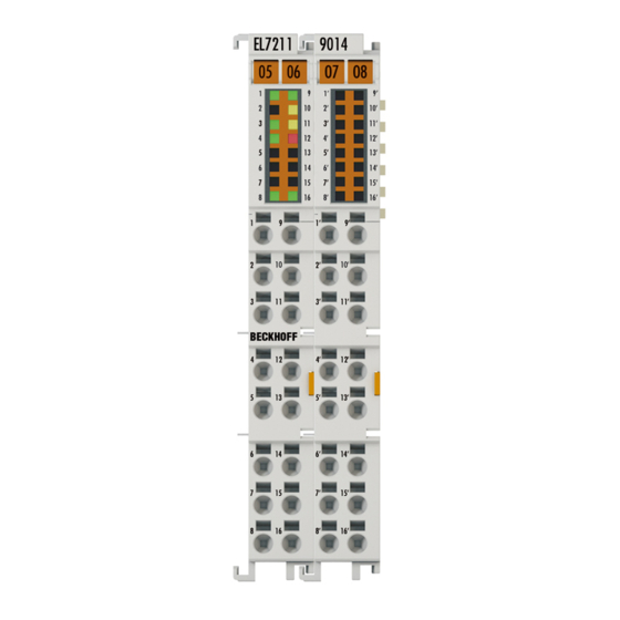
Integrated safety Fig. 211: Dimensions of the EL7211-xxxx Width: 24 mm (side-by-side installation) Height: 100 mm Depth: 68 mm 6.2.3 TwinSAFE reaction times The TwinSAFE terminals form a modular safety system that exchanges safety-oriented data via the Safety- over-EtherCAT protocol. This chapter is intended to help you determine the system's reaction time from the change of signal at the sensor to the reaction at the actuator. -
Page 179: Fig. 213 Worst-Case Reaction Time
Integrated safety Definition Description RTSensor Reaction time of the sensor until the signal is provided at the interface. Typically supplied by the sensor manufacturer. RTInput Reaction time of the safe input, such as EL1904 or EP1908. This time can be found in the technical data. -
Page 180: Application Example For Sto Function (Cat. 3, Pl D)
Integrated safety 6.2.4 Application example for STO function (Cat. 3, PL d) Application example (STO – Safe Torque Off) The following application example shows how the EL72x1-9014 can be wired together with an EL2904 in order to implement an STO function according to EN 61800-5-2. The user must realize an appropriate evaluation for the wiring between the safety output terminal (EL2904) and the servo terminal (EL72x1-9014), so that a fault exclusion is permissible for external supply and cross- circuit in this wiring. -
Page 181: Fig. 214 Connection Example For El72X1_9014 With Sto
Integrated safety Fig. 214: Connection example for EL72x1_9014 with STO CAUTION Implement a restart lock in the machine! The restart lock is NOT part of the safety chain and must be implemented in the machine! If the risk analysis returns the result that a restart is to be realized in the safety controller, then the restart must also be placed on a safe input. -
Page 182: Fig. 215 El72X1_9014_Block_Diagram
Integrated safety Parameters of the safe input and output terminals EL1904 Parameter Value Sensor test channel 1 active Sensor test channel 2 active Sensor test channel 3 active Sensor test channel 4 active Logic channel 1 and 2 Single Logic Logic channel 3 and 4 Single Logic EL2904... - Page 183 Integrated safety Calculation for block 1 Calculation of the PFH and MTTF values from the B10 values: From: and: Inserting the values, this produces: and the assumption that S1 and S2 are each single-channel: produces for EL72x1-901x Version: 1.9...
- Page 184 Integrated safety The following assumptions must now be made: The door switches S1/S2 are always actuated in opposite directions. Since the switches have different values, but the complete protective door switch consists of a combination of normally closed and normally open contacts and both switches must function, the poorer of the two values (S1) can be taken for the combination! There is a coupling coefficient between the components that are connected via two channels.
- Page 185 Integrated safety Hence: CAUTION Category This structure is possible up to category 3 at the most. EL72x1-901x Version: 1.9...
-
Page 186: Maintenance
Integrated safety Manufacturer data for interface type C – Senke Parameter min. typically max. Class Test pulse duration t 500 µs Test pulse interval T 10 ms Input resistance R 4.7 kΩ Input capacitance C 1.21 µF The Testing parameter can be switched on in conjunction with the EL2904. Maintenance Maintenance The TwinSAFE components are maintenance-free! -
Page 187: Fig. 216 Unique Serial Number Of A Twinsafe Terminal
Integrated safety Legend: Sample: Date Code 17 11 05 00 CW: Calendar week of manufacture Calendar week: 17 YY: Year of manufacture Year: 2011 SW: Software version Software version: 05 HW: Hardware version Hardware version: 00 In addition the TwinSAFE terminals bear a unique serial number. Fig. 216: Unique serial number of a TwinSAFE terminal EL72x1-901x Version: 1.9... -
Page 188: Object Description And Parameterization
EtherCAT XML Device Description The display matches that of the CoE objects from the EtherCAT XML Device Description. We rec- ommend downloading the latest XML file from the download area of the Beckhoff website and in- stalling it according to installation instructions. - Page 189 Object description and parameterization Index 8008 FB OCT Settings Index (hex) Name Meaning Data type Flags Default 8008:0 FB OCT Settings Maximum subindex UINT8 0x00 (0 8008:01 Enable autoconfig Configuration takes place automatically after the read- BOOLEAN 0x00 (0 ing of the electronic type plate (see Automatic scanning of the electronic type plates [} 143]) 8008:02...
- Page 190 Object description and parameterization Index 8010 DRV Amplifier Settings Index (hex) Name Meaning Data type Flags Default 8010:0 DRV Amplifier Settings Maximum subindex UINT8 0x42 (66 8010:01 Enable TxPDOToggle Show TxPDO toggle in status word (bit 10) BOOLEAN 0x00 (0 8010:02 Enable input cycle 1: activated...
- Page 191 Object description and parameterization Index (hex) Name Meaning Data type Flags Default 8010:39 Select info data 1 Selection "Info data 1" UINT8 0x01 (1 Optional display of additional information in the cyclic process data. Permitted values: Torque current (filtered 1ms) [1000th of rated current] DC link voltage (mV) PCB temperature (0.1 °C) Errors:...
- Page 192 Object description and parameterization Index (hex) Name Meaning Data type Flags Default 8010:41 Low-pass filter fre- Low-pass filter frequency UINT16 0x0140 quency Unit: Hz (320 The following values can be set: 0 Hz = off 160 Hz 320 Hz 8010:49 Halt ramp deceleration Halt ramp deceleration UINT32 0x0000F570...
- Page 193 Object description and parameterization Index 8011 DRV Motor Settings Index (hex) Name Meaning Data type Flags Default 8011:0 DRV Motor Settings Maximum subindex UINT8 0x2D (45 8011:11* Max current Peak current UINT32 0x00001770 Unit: mA (6000 The adjustable motor current values can be interpreted as peak values or rms values.
-
Page 194: Fig. 39 Note
Object description and parameterization Index (hex) Name Meaning Data type Flags Default 8011:29 I2T warn level I2T model warning threshold UINT8 0x50 (80 Unit: % 8011:2A I2T error level I2T model error threshold UINT8 0x69 (105 Unit: % 8011:2B* Motor Temperature Overtemperature warning threshold UINT16 0x03E8... -
Page 195: Configuration Data (Vendor-Specific)
Object description and parameterization 7.1.3 Configuration data (vendor-specific) Index 801F DRV Vendor data Index (hex) Name Meaning Data type Flags Default 801F:0 DRV Vendor data Maximum subindex UINT8 0x14 (20 801F:11 Amplifier peak current Peak current of the amplifier (peak value) UINT32 0x00001F40 Unit: mA... - Page 196 Object description and parameterization Index 6001 FB Touch probe inputs Index (hex) Name Meaning Data type Flags Default 6001:0 FB Touch probe inputs Maximum subindex UINT8 0x14 (20 6001:01 TP1 Enable Touchprobe 1 switched on BOOLEAN 0x00 (0 6001:02 TP1 pos value stored Positive value of Touchprobe 1 saved BOOLEAN 0x00 (0...
-
Page 197: Output Data
Object description and parameterization 7.1.6 Output data Index 7001 FB Touch probe outputs Index (hex) Name Meaning Data type Flags Default 7001:0 FB Touch probe out- Maximum subindex UINT8 0x0E (14 puts 7001:01 TP1 Enable Switch on Touchprobe 1 BOOLEAN 0x00 (0 7001:02 TP1 Continous... - Page 198 Object description and parameterization Index 7010 DRV Outputs Index (hex) Name Meaning Data type Flags Default 7010:0 DRV Outputs Maximum subindex UINT8 0x0E (14 7010:01 Controlword Controlword UINT16 0x0000 (0 Bit 0: Switch on Bit 1: Enable voltage Bit 2: Quick stop (inverse) Bit 3: Enable operation Bit 4 - 6: reserved Bit 7: Fault reset...
-
Page 199: Information / Diagnosis Data
Object description and parameterization 7.1.7 Information / diagnosis data Index 10F3 Diagnosis History Index (hex) Name Meaning Data type Flags Default 10F3:0 Diagnosis History Maximum subindex UINT8 0x37 (55 10F3:01 Maximum Messages Maximum number of stored messages. A maximum of UINT8 0x00 (0 50 messages can be stored... - Page 200 Object description and parameterization Index (hex) Name Meaning Data type Flags Default 9009:0 FB OCT Nameplate Maximum subindex UINT8 0x24 (36 9009:01 Motor vendor Motor vendor STRING 9009:02 Electric motor type Motor type STRING 9009:03 Serial No Serial number STRING 9009:04 Order code Order number...
- Page 201 Object description and parameterization Index (hex) Name Meaning Data type Flags Default 9009:13 Max speed Maximum speed UINT32 0x00000000 Unit: rpm 9009:14 Moment of inertia Mass moment of inertia UINT16 0x0000 (0 Unit: g cm^2 9009:15 T motor warn limit Motor temperature warning threshold UINT16 0x0000 (0...
-
Page 202: Standard Objects
Object description and parameterization Index 9018 DRV Info data Index (hex) Name Meaning Data type Flags Default 9018:0 DRV Info data Maximum subindex UINT8 0x11 (17 9018:11 Auxiliary voltage (10 Auxiliary voltage UINT32 0x00000000 Unit: mV Index A010 DRV Amplifier Diag data Index (hex) Name Meaning Data type... - Page 203 Object description and parameterization Index 10F0 Backup parameter handling Index (hex) Name Meaning Data type Flags Default 10F0:0 Backup parameter Information for standardized loading and saving of UINT8 0x01 (1 handling backup entries 10F0:01 Checksum Checksum across all backup entries of the EtherCAT UINT32 0x00000000 slave...
- Page 204 Object description and parameterization Index 1607 FB RxPDO-Map Touch probe control Index (hex) Name Meaning Data type Flags Default 1607:0 FB RxPDO-Map PDO Mapping RxPDO 8 UINT8 0x0C (12 Touch probe control 1607:01 SubIndex 001 1. PDO Mapping entry (object 0x7001 (FB Touch UINT32 0x7001:01, 1 probe outputs), entry 0x01 (TP1 Enable))
- Page 205 Object description and parameterization Index 1A04 DRV TxPDO-Map Info data 1 Index (hex) Name Meaning Data type Flags Default 1A04:0 DRV TxPDO-Map Info PDO Mapping TxPDO 5 UINT8 0x01 (1 data 1 1A04:01 SubIndex 001 1. PDO Mapping entry (object 0x6010 (DRV Inputs), UINT32 0x6010:12, 16 entry 0x12 (Info data 1))
- Page 206 Object description and parameterization Index 1A0A FB TxPDO-Map Touch probe 2 pos position Index (hex) Name Meaning Data type Flags Default 1A0A:0 FB TxPDO-Map Touch PDO Mapping TxPDO 11 UINT8 0x01 (1 probe 2 pos position 1A0A:01 SubIndex 001 1. PDO Mapping entry (object 0x6001 (FB Touch UINT32 0x6001:13, 32 probe inputs), entry 0x13 (TP2 Pos position))
- Page 207 Object description and parameterization Index 1C13 TxPDO assign Index (hex) Name Meaning Data type Flags Default 1C13:0 TxPDO assign PDO Assign Inputs UINT8 0x03 (3 1C13:01 Subindex 001 1. allocated TxPDO (contains the index of the associ- UINT16 0x1A00 ated TxPDO mapping object) (6656 1C13:02 Subindex 002...
- Page 208 Object description and parameterization Index 1C32 SM output parameter Index (hex) Name Meaning Data type Flags Default 1C32:0 SM output parameter Synchronization parameters for the outputs UINT8 0x20 (32 1C32:01 Sync mode Current synchronization mode: UINT16 0x0000 (0 • 3: DC-Mode - Synchron with SYNC1 Event 1C32:02 Cycle time Cycle time (in ns):...
- Page 209 Object description and parameterization Index 1C33 SM input parameter Index (hex) Name Meaning Data type Flags Default 1C33:0 SM input parameter Synchronization parameters for the inputs UINT8 0x20 (32 1C33:01 Sync mode Current synchronization mode: UINT16 0x0000 (0 • 3: DC - Synchron with SYNC1 Event 1C33:02 Cycle time UINT32...
- Page 210 Object description and parameterization Index FB40 Memory interface Index (hex) Name Meaning Data type Flags Default FB40:0 Memory interface Maximum subindex UINT8 0x03 (3 FB40:01 Address reserved UINT32 0x00000000 FB40:02 Length reserved UINT16 0x0000 (0 FB40:03 Data reserved OCTET- STRING[8] Version: 1.9 EL72x1-901x...
-
Page 211: El72X1-9014 (Ds402)
EtherCAT XML Device Description The display matches that of the CoE objects from the EtherCAT XML Device Description. We rec- ommend downloading the latest XML file from the download area of the Beckhoff website and in- stalling it according to installation instructions. -
Page 212: Configuration Data
Object description and parameterization 7.2.1 Configuration data Index 2002 Amplifier Settings Index (hex) Name Meaning Data type Flags Default 2002:0 Amplifier Settings Maximum subindex UINT8 0x49 (73 2002:11 Device type 1: Servo drive (cannot be changed) UINT32 0x00000001 (1 2002:12* Current loop integral Integral component of current controller UINT16... - Page 213 Object description and parameterization Index (hex) Name Meaning Data type Flags Default 2002:53 Position loop propor- Proportional component position controller UINT32 0x00000000 (0 tional gain Unit: mA / (rad/s) 2002:54 Feature bits The adjustable motor current values can be interpreted UINT32 0x00000000 (0 as peak values or rms values.
- Page 214 Object description and parameterization Index (hex) Name Meaning Data type Flags Default 2002:56 Select info data 2 Selection "Info data 2" UINT8 0x00 (0 Optional display of additional information in the cyclic process data. Permitted values: Torque current (filtered 1ms) [1000th of rated current] DC link voltage (mV) PCB temperature (0.1 °C) Errors:...
- Page 215 Object description and parameterization Index 2003 Motor Settings Index (hex) Name Meaning Data type Flags Default 2003:0 Motor Settings Maximum subindex UINT8 0x2D (45 2003:11* Max current Peak current UINT32 0x00001770 Unit: mA (6000 The adjustable motor current values can be interpreted as peak values or rms values.
- Page 216 Object description and parameterization Index 2004 Brake Settings Index (hex) Name Meaning Data type Flags Default 2004:0 Brake Settings Maximum subindex UINT8 0x14 (20 2004:01 Manual override (re- Manual release of the motor holding brake BOOLEAN 0x00 (0 lease) 2004:11* Release delay Time the holding brake requires for opening (releasing) UINT16...
-
Page 217: Configuration Data (Vendor-Specific)
Object description and parameterization Index 2018 OCT Settings Index (hex) Name Meaning Data type Flags Default 2018:0 OCT Settings Maximum subindex UINT8 0x03 (3 2018:01 Enable auto config Configuration takes place automatically after the read- BOOLEAN 0x00 (0 ing of the electronic type plate (see Automatic scanning of the electronic type plates [} 143]) 2018:02... -
Page 218: Input/Output Data
Object description and parameterization 7.2.4 Input/output data Index 2001 Outputs Index (hex) Name Meaning Data type Flags Default 2001:0 Outputs Maximum subindex UINT8 0x11 (17 2001:11 Torque offset Torque value offset INT16 0x0000 (0 The value is specified in 1000th of the rated current Equation for index 2002:54 [} 212] = 0 : M = ((Torque actual value / 1000) x (rated current / √2)) x torque constant (2003:16 [} 215]) - Page 219 Object description and parameterization Index 605E Fault reaction option code Index (hex) Name Meaning Data type Flags Default 605E:0 Fault reaction option 0: Disable drive function, motor is free to rotate ENUM16BIT code 1: Slow down by slow down ramp Index 6060 Modes of operation Index (hex) Name Meaning...
- Page 220 Object description and parameterization Index 6071 Target torque Index (hex) Name Meaning Data type Flags Default 6071:0 Target torque This object shall indicate the configured input value for INT16 0x0000 (0 the torque controller. The value is specified in 1000th of the rated current. Equation for index 2002:54 [} 212] = 0 : M = ((Torque actual value / 1000) x (rated current / √2)) x torque constant (2003:16 [} 215])
- Page 221 Object description and parameterization Index 607A Target position Index (hex) Name Meaning Data type Flags Default 607A:0 Target position This object shall provide the actual position. INT32 0x00000000 Unit: the given value must be multiplied by the corre- sponding scaling factor [} 130] Index 6080 Max motor speed Index (hex) Name Meaning...
- Page 222 Object description and parameterization Index 60BC Touch probe 2 positive edge Index (hex) Name Meaning Data type Flags Default 60BC:0 Touch probe 2 positive Positive position value of TP 2 INT32 0x00000000 edge Unit: the given value must be multiplied by the corre- sponding scaling factor [} 130] Index 60BD Touch probe 2 negative edge Index (hex) Name...
-
Page 223: Information / Diagnosis Data
Object description and parameterization Index 6502 Supported drive modes Index (hex) Name Meaning Data type Flags Default 6502:0 Supported drive This object shall provide information on the supported UINT32 0x00000000 modes drive modes. (DS402 Object 0x6502) Only modes CSV, CST, CSTCA and CSP are sup- ported Bit 0: PP Bit 1: VL... - Page 224 Object description and parameterization Index 2040 Amplifier Info data Index (hex) Name Meaning Data type Flags Default 2040:0 Amplifier Info data Maximum subindex UINT8 0x12 (18 2040:11 Amplifier temperature Internal terminal temperature UINT16 0x0000 (0 Unit: 0.1 °C 2040:12 DC link voltage DC link voltage UINT32 0x00000000...
- Page 225 Object description and parameterization Index (hex) Name Meaning Data type Flags Default 2059:0 OCT Nameplate Maximum subindex UINT8 0x24 (36 2059:01 Motor vendor Motor vendor STRING 2059:02 Electric motor type Motor type STRING 2059:03 Serial No Serial number STRING 2059:04 Order code Order number STRING...
-
Page 226: Standard Objects
Object description and parameterization Index (hex) Name Meaning Data type Flags Default 2059:13 Max speed Maximum speed UINT32 0x00000000 Unit: rpm 2059:14 Moment of inertia Mass moment of inertia UINT16 0x0000 (0 Unit: g cm^2 2059:15 T motor warn limit Motor temperature warning threshold UINT16 0x0000 (0... - Page 227 Object description and parameterization Index 100A Software version Index (hex) Name Meaning Data type Flags Default 100A:0 Software version Firmware-Version des EtherCAT-Slaves STRING Index 1018 Identity Index (hex) Name Meaning Data type Flags Default 1018:0 Identity Information for identifying the slave UINT8 0x04 (4 1018:01...
- Page 228 Object description and parameterization Index 1606 DS402 RxPDO-Map Target position Index (hex) Name Meaning Data type Flags Default 1606:0 DS402 RxPDO-Map PDO Mapping RxPDO 7 UINT8 0x01 (1 Target position 1606:01 SubIndex 001 1. PDO Mapping entry UINT32 0x607A:00, 32 Index 1607 DS402 RxPDO-Map Touch probe function Index (hex) Name Meaning...
- Page 229 Object description and parameterization Index 1A07 DS402 TxPDO-Map Touch probe 1 negative edge Index (hex) Name Meaning Data type Flags Default 1A07:0 DS402 TxPDO-Map PDO Mapping TxPDO 8 UINT8 0x01 (1 Touch probe 1 nega- tive edge 1A07:01 SubIndex 001 1.
- Page 230 Object description and parameterization Index 1C12 RxPDO assign Index (hex) Name Meaning Data type Flags Default 1C12:0 RxPDO assign PDO Assign Outputs UINT8 0x02 (2 1C12:01 Subindex 001 1. allocated RxPDO (contains the index of the associ- UINT16 0x1600 ated RxPDO mapping object) (5632 1C12:02 Subindex 002...
- Page 231 Object description and parameterization Index 1C32 SM output parameter Index (Hex) Name Meaning Data type Flags Default 1C32:0 SM output parameter Synchronization parameters for the outputs UINT8 0x20 (32 1C32:01 Sync mode Current synchronization mode: UINT16 0x0000 (0 • 3: DC-Mode - Synchronous with SYNC1 event 1C32:02 Cycle time Cycle time (in ns):...
- Page 232 Object description and parameterization Index 1C33 SM input parameter Index (hex) Name Meaning Data type Flags Default 1C33:0 SM input parameter Synchronization parameters for the inputs UINT8 0x20 (32 1C33:01 Sync mode Current synchronization mode: UINT16 0x0000 (0 • 3: DC - Synchronous with SYNC1 Event 1C33:02 Cycle time UINT32...
-
Page 233: Error Correction
The DiagMessages are explained in text form in the ESI/XML file belonging to the EtherCAT device: on the basis of the Text ID contained in the DiagMessage, the corresponding plain text message can be found in the languages contained in the ESI/XML. In the case of Beckhoff products these are usually German and English. -
Page 234: Fig. 218 Implementation Of The Diagmessage System In The Twincat System Manager
Error correction Support for commissioning The DiagMessages system is to be used above all during the commissioning of the plant. The diag- nostic values e.g. in the StatusWord of the device (if available) are helpful for online diagnosis dur- ing the subsequent continuous operation. TwinCAT System Manager implementation From TwinCAT 2.11 DiagMessages, if available, are displayed in the device’s own interface. - Page 235 Structure of the Text ID The structure of the MessageID is not subject to any standardization and can be supplier-specifically defined. In the case of Beckhoff EtherCAT devices (EL, EP) it usually reads according to xyzz: 0: Systeminfo 0: System...
- Page 236 Error correction Text ID Type Place Text Message Additional comment 0x0001 Information System No error No error 0x0002 Information System Communication estab- Connection established lished 0x0003 Information System Initialization: 0x%X, 0x General information; parameters depend on event. %X, 0x%X See device documentation for interpretation. 0x1000 Information System...
- Page 237 Error correction Text ID Type Place Text Message Additional comment 0x2000 Information System %s: %s 0x2001 Information System %s: Network link lost Network connection lost 0x2002 Information System %s: Network link de- Network connection found tected 0x2003 Information System %s: no valid IP Configu- Invalid IP configuration ration - Dhcp client started...
- Page 238 Error correction Text ID Type Place Text Message Additional comment 0x4000 Warning Warning: 0x%X, 0x%X, General warning; parameters depend on event. See 0x%X device documentation for interpretation. 0x4001 Warning System Warning: 0x%X, 0x%X, 0x%X 0x4002 Warning System %s: %s Connection Open (IN:%d OUT:%d API:%dms) from %d.%d.
- Page 239 Error correction Text ID Type Place Text Message Additional comment 0x4414 Warning Drive I2T-Model Motor over- - The motor is being operated outside the parameter- load (Warning) ized rated values - The I2T-model of the motor is incorrectly parameter- ized 0x4415 Warning Drive...
- Page 240 Error correction Text ID Type Place Text Message Additional comment 0x8000 Error System %s: %s 0x8001 Error System Error: 0x%X, 0x%X, 0x General error; parameters depend on event. See de- vice documentation for interpretation. 0x8002 Error System Communication aborted Communication aborted 0x8003 Error System...
- Page 241 Error correction Text ID Type Place Text Message Additional comment 0x8288 Error Communication Reading Certificate EK failed: %X 0x8289 Error Communication Challenge could not be hashed: %X 0x828A Error Communication Tickstamp Process failed 0x828B Error Communication PCR Process failed: %X 0x828C Error Communication Quote Process failed:...
- Page 242 Error correction Text ID Type Place Text Message Additional comment 0x841C Error Drive STO while the axis was An attempt was made to activate the axis, despite the enabled fact that no voltage is present at the STO input. 0x8550 Error Inputs Zero crossing phase %X...
-
Page 243: Appendix
Note • It is recommended to use the newest possible firmware for the respective hardware • Beckhoff is not under any obligation to provide customers with free firmware updates for delivered products. NOTE Risk of damage to the device! Pay attention to the instructions for firmware updates on the separate page. -
Page 244: Firmware Update El/Es/Em/Elm/Epxxxx
Check on the Beckhoff web page whether more up-to-date documentation is available. Firmware Update EL/ES/EM/ELM/EPxxxx This section describes the device update for Beckhoff EtherCAT slaves from the EL/ES, ELM, EM, EK and EP series. A firmware update should only be carried out after consultation with Beckhoff support. -
Page 245: Device Description Esi File/Xml
The device revision is closely linked to the firmware and hardware used. Incompatible combinations lead to malfunctions or even final shutdown of the device. Corresponding updates should only be carried out in consultation with Beckhoff support. Display of ESI slave identifier... -
Page 246: Fig. 220 Scan The Subordinate Field By Right-Clicking On The Ethercat Device
Appendix Fig. 220: Scan the subordinate field by right-clicking on the EtherCAT device If the found field matches the configured field, the display shows Fig. 221: Configuration is identical otherwise a change dialog appears for entering the actual data in the configuration. Fig. 222: Change dialog In this example in Fig. -
Page 247: Fig. 223 Eeprom Update
Appendix Changing the ESI slave identifier The ESI/EEPROM identifier can be updated as follows under TwinCAT: • Trouble-free EtherCAT communication must be established with the slave. • The state of the slave is irrelevant. • Right-clicking on the slave in the online display opens the EEPROM Update dialog, Fig. EEPROM Update Fig. 223: EEPROM Update The new ESI description is selected in the following dialog, see Fig. -
Page 248: Firmware Explanation
• offline: The EtherCAT Slave Information ESI/XML may contain the default content of the CoE. This CoE directory can only be displayed if it is included in the ESI (e.g. "Beckhoff EL5xxx.xml"). The Advanced button must be used for switching between the two views. -
Page 249: Updating Controller Firmware *.Efw
Switch to the Online tab to update the controller firmware of a slave, see Fig. Firmware Update. Fig. 226: Firmware Update Proceed as follows, unless instructed otherwise by Beckhoff support. Valid for TwinCAT 2 and 3 as EtherCAT master. • Switch TwinCAT system to ConfigMode/FreeRun with cycle time >= 1 ms (default in ConfigMode is 4 ms). -
Page 250: Fpga Firmware *.Rbf
Appendix • Switch EtherCAT Master to PreOP • Switch slave to INIT (A) • Switch slave to BOOTSTRAP • Check the current status (B, C) • Download the new *efw file (wait until it ends). A pass word will not be neccessary usually. •... - Page 251 Appendix Fig. 227: FPGA firmware version definition If the column Reg:0002 is not displayed, right-click the table header and select Properties in the context menu. Fig. 228: Context menu Properties The Advanced Settings dialog appears where the columns to be displayed can be selected. Under Diagnosis/Online View select the '0002 ETxxxx Build' check box in order to activate the FPGA firmware version display.
- Page 252 Older firmware versions can only be updated by the manufacturer! Updating an EtherCAT device The following sequence order have to be met if no other specifications are given (e.g. by the Beckhoff support): • Switch TwinCAT system to ConfigMode/FreeRun with cycle time >= 1 ms (default in ConfigMode is 4 ms).
- Page 253 Appendix • In the TwinCAT System Manager select the terminal for which the FPGA firmware is to be updated (in the example: Terminal 5: EL5001) and click the Advanced Settings button in the EtherCAT tab: • The Advanced Settings dialog appears. Under ESC Access/E²PROM/FPGA click on Write FPGA button: EL72x1-901x Version: 1.9...
-
Page 254: Simultaneous Updating Of Several Ethercat Devices
Appendix • Select the file (*.rbf) with the new FPGA firmware, and transfer it to the EtherCAT device: • Wait until download ends • Switch slave current less for a short time (don't pull under voltage!). In order to activate the new FPGA firmware a restart (switching the power supply off and on again) of the EtherCAT device is required. -
Page 255: Restoring The Delivery State
Appendix Restoring the delivery state To restore the delivery state for backup objects in ELxxxx terminals, the CoE object Restore default parameters, SubIndex 001 can be selected in the TwinCAT System Manager (Config mode) (see Fig. Selecting the Restore default parameters PDO) Fig. 231: Selecting the "Restore default parameters"... -
Page 256: Certificates
Appendix Certificates Fig. 233: EL72x1-9014_Certificate Version: 1.9 EL72x1-901x... -
Page 257: Support And Service
Beckhoff's branch offices and representatives Please contact your Beckhoff branch office or representative for local support and service on Beckhoff products! The addresses of Beckhoff's branch offices and representatives round the world can be found on her internet pages: http://www.beckhoff.com You will also find further documentation for Beckhoff components there. - Page 258 Startup list in the TwinCAT System Manager ................Fig. 19 Offline list ............................. Fig. 20 Online list ............................ Fig. 21 Spring contacts of the Beckhoff I/O components................. Fig. 22 Attaching on mounting rail ......................Fig. 23 Disassembling of terminal......................Fig. 24 Power contact on left side......................
- Page 259 Table of figures Fig. 42 EL7211-901x, EL7221-901x - LEDs .................... Fig. 43 EL7211-901x, EL7221-901x - Connection................... Fig. 44 Relationship between user side (commissioning) and installation..........Fig. 45 Control configuration with Embedded PC, input (EL1004) and output (EL2008) ......Fig. 46 Initial TwinCAT 2 user interface....................
- Page 260 Table of figures Fig. 88 Incorrect driver settings for the Ethernet port ................Fig. 89 TCP/IP setting for the Ethernet port .................... Fig. 90 Identifier structure ........................Fig. 91 OnlineDescription information window (TwinCAT 2) ..............Fig. 92 Information window OnlineDescription (TwinCAT 3) ..............Fig.
- Page 261 Table of figures Fig. 132 “Process Data” tab........................108 Fig. 133 Configuring the process data....................... 109 Fig. 134 „Startup“ tab..........................110 Fig. 135 “CoE – Online” tab ........................111 Fig. 136 Dialog “Advanced settings”......................112 Fig. 137 „Online“ tab ..........................112 Fig.
- Page 262 Table of figures Fig. 178 Pull-down menu for activating end position monitoring .............. 145 Fig. 179 Online homing in the NC......................146 Fig. 180 Configuration of the MC_Home block..................147 Fig. 181 Extraction from the functional description for MC_Home ............147 Fig.
- Page 263 Table of figures Fig. 224 Selecting the new ESI........................247 Fig. 225 Display of EL3204 firmware version .................... 248 Fig. 226 Firmware Update ......................... 249 Fig. 227 FPGA firmware version definition ....................251 Fig. 228 Context menu Properties ......................251 Fig.
Need help?
Do you have a question about the EL72 1-901 Series and is the answer not in the manual?
Questions and answers