
Subscribe to Our Youtube Channel
Related Manuals for Beckhoff EL6910


Summary of Contents for Beckhoff EL6910
- Page 1 Operation Manual for EL6910 TwinSAFE Logic Terminal Version: 1.4.1 Date: 2017-02-07...
-
Page 3: Table Of Contents
1.2.3 Description of safety symbols .................... 7 Documentation issue status...................... 8 2 TwinSAFE System Description ........................ 9 Extension of the Beckhoff I/O system with safety functions ............ 9 Safety concept .......................... 9 3 Product description.......................... 10 EL6910 - TwinSAFE logic terminal .................... 10 Intended use .......................... - Page 4 TwinSAFE SC configuration ...................... 86 4.14 Customizing / disabling TwinSAFE groups................... 90 4.15 Saving the analog group inputs persistently ................. 93 4.16 Project design limits of EL6910/EJ6910 .................. 93 4.17 Diagnostics ........................... 94 4.17.1 Diagnostic LEDs....................... 94 4.17.2 Status LEDs ........................ 96 4.17.3 Diagnostic objects ...................... 97 4.17.4 Cycle time of the safety project .................. 98...
-
Page 5: Foreword
Product features Only the product features specified in the current user documentation are valid. Further information given on the product pages of the Beckhoff homepage, in emails or in other publications is not authoritative. Disclaimer The documentation has been prepared with care. The products described are subject to cyclical revision. For that reason the documentation is not in every case checked for consistency with performance data, standards or other characteristics. -
Page 6: Safety Instructions
Offenders will be held liable for the payment of damages. All rights reserved in the event of the grant of a patent, utility model or design. Delivery conditions In addition, the general delivery conditions of the company Beckhoff Automation GmbH & Co. KG apply. Safety instructions 1.2.1... -
Page 7: Description Of Safety Symbols
Damage to the environment or devices Failure to follow the instructions associated with this symbol can lead to damage to the en- vironment or equipment. Attention Tip or pointer This symbol indicates information that contributes to better understanding. Note EL6910 Version: 1.4.1... -
Page 8: Documentation Issue Status
• System description updated 0.0.6 • Online display extended 0.0.5 • TwinSAFE group description extended 0.0.4 • PROFIsafe master/slave description extended 0.0.3 • Customizing extended 0.0.2 • Creating network and group descriptions 0.0.1 • Creation of the document Version: 1.4.1 EL6910... -
Page 9: Twinsafe System Description
(e.g. EL19xx, EP1908), digital outputs (e.g. EL29xx), drive components (e.g. AX5805) and logic units (e.g. EL6900, EL6910). For a large number of applications, the complete safety sensor and actuator technology can be wired on these components. The required logical link of the inputs and the outputs is handled by the EL69xx. -
Page 10: Product Description
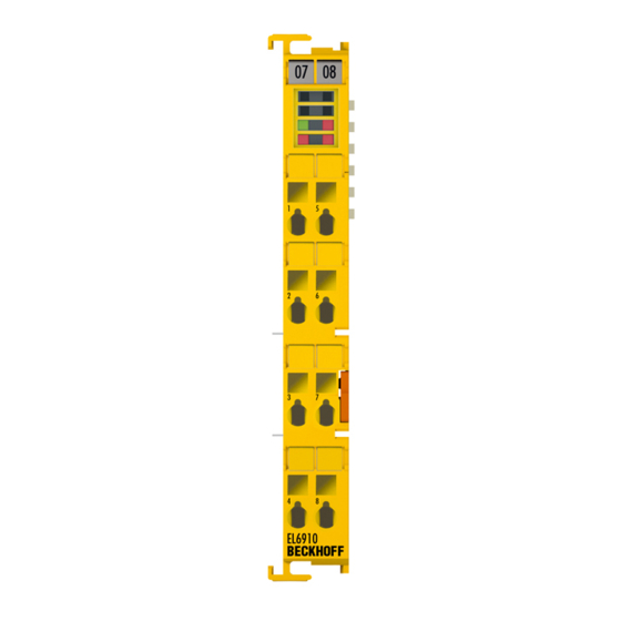
Product description EL6910 - TwinSAFE logic terminal The TwinSAFE logic terminal is the link unit between the TwinSAFE inputs and outputs. The EL6910 meets the requirements of IEC 62061:2005/A2:2015, IEC 61508:2010 SIL 3 and DIN EN ISO 13849-1:2016-06 (Cat 4, PL e). Fig. 1: EL6910 - TwinSAFE logic terminal Version: 1.4.1... -
Page 11: Intended Use
• Beckhoff CXxxxx series Embedded PCs with E-bus connection System limits The TÜV SÜD certificate applies to the EL6910, the function blocks available in it, the doc- umentation and the engineering tool. Approved engineering tools are TwinCAT 3.1, Twin- WARNING SAFE Loader and CODESYS Safety for EtherCAT Safety Module. -
Page 12: Technical Data
Product description Technical data Product designation EL6910 Number of inputs Number of outputs Status display 4 diagnostic LEDs Minimum/maximum cycle time approx. 1 ms / according the project size Error reaction time ≤ watchdog times Watchdog time min. 2 ms, max. 60000 ms Input process image Dynamic, according to the TwinSAFE configuration in TwinCAT 3... -
Page 13: Safety Parameters
Element classification* Type B 1. Special proof tests are not required during the entire service life of the EL6910 EtherCAT terminal. 2. Classification according to IEC 61508-2:2010 (see chapters 7.4.4.1.2 and 7.4.4.1.3) The EL6910 EtherCAT Terminal can be used for safety-related applications according to IEC62061 and IEC 61508:2010 up to SIL3 and DIN EN ISO 13849-1:2016-06 up to PL e (Cat4). -
Page 14: Dimensions
Product description Dimensions Fig. 2: Dimensions of the EL6910 Width: 12 mm (side-by-side installation) Height: 100 mm Depth: 68 mm Version: 1.4.1 EL6910... -
Page 15: Operation
Bring the bus system into a safe, de-energized state before starting installation, disassem- bly or wiring of the devices! DANGER 4.2.3.1 Control cabinet / terminal box The TwinSAFE terminals must be installed in a control cabinet or terminal box with IP54 protection class according to IEC 60529 as a minimum. EL6910 Version: 1.4.1... -
Page 16: Fig. 3 Installation Position And Minimum Distances
Fig. 3: Installation position and minimum distances In order to ensure optimum convection cooling, the distances to neighboring devices and to control cabinet walls must not be smaller than those shown in the diagram. Version: 1.4.1 EL6910... -
Page 17: Fig. 4 Sample Configuration For Temperature Measurement
The sample configuration for the temperature measurement consists of an EK1100 EtherCAT coupler with connected terminals that match the typical distribution of digital and analog signal types at a machine. On the EL6910 a safety project is active, which reads safe inputs and enables all 4 safe outputs during the measurement. -
Page 18: Fig. 5 Installation On The Mounting Rail
For fastening mounting rails with a height of 7.5 mm under the terminals and couplers, use flat fastening compo- nents such as countersunk head screws or blind rivets. Version: 1.4.1 EL6910... -
Page 19: Electrical Installation
(e.g. analog Bus Terminals or digital 4- Note channel Bus Terminals) do not or not fully loop through the power contacts. Power Feed Terminals (EL91xx, EL92xx) interrupt the power contacts and thus represent the start of a new supply rail. EL6910 Version: 1.4.1... -
Page 20: Fig. 7 Pe Power Contact
The PE power contact must not be used for other potentials! DANGER 4.2.4.2 Overvoltage protection If protection against overvoltage is necessary in your plant, provide a surge filter for the voltage supply to the Bus Terminal blocks and the TwinSAFE terminals. Version: 1.4.1 EL6910... -
Page 21: Fig. 8 Connection Of A Cable To A Terminal Point
2. The wire can now be inserted into the round terminal opening without any force. 3. The terminal closes automatically when the pressure is released, holding the wire safely and perma- nently. Wire cross section 0,08 ... 2.5 mm Strip length 8 ... 9 mm EL6910 Version: 1.4.1... -
Page 22: Fig. 9 El6900/El6910 Pin Assignment
Operation 4.2.4.4 EL6900/EL6910 pin assignment Fig. 9: EL6900/EL6910 pin assignment Terminal point Output Signal not used, no function not used, no function not used, no function not used, no function not used, no function not used, no function not used, no function not used, no function Version: 1.4.1... -
Page 23: Twinsafe Reaction Times
This results in the following equation for the typical reaction time: with, for example Worst-case reaction time The worst case reaction time is the maximum time required to switch off the actuator in the case of an error. EL6910 Version: 1.4.1... -
Page 24: Fig. 11 Worst-Case Reaction Time
This error is detected at the output following the expiry of the watchdog time and leads to the switch-off. This results in the following equation for the worst-case reaction: with, for example Version: 1.4.1 EL6910... -
Page 25: Operation In Potentially Explosive Atmospheres (Atex)
• EN 60079-0: 2103 • EN 60079-15: 2011 4.3.2 Identification Beckhoff fieldbus components that are certified for use in potentially explosive atmospheres bear one of the following markings: II 3 G Ex nA II T4 KEMA 10ATEX0075 X Ta: 0 - 55°C II 3 G Ex nA nC IIC T4 KEMA 10ATEX0075 X Ta: 0 - 55°C... -
Page 26: Further Atex Documentation
Adding an EtherCAT Terminal See TwinCAT 3 automation software documentation. 4.4.4 Adding an EL6910 An EL6910 is added in exactly the same way as any other Beckhoff EtherCAT Terminal. In the list, open Safety Terminals and select the EL6910. Version: 1.4.1 EL6910... -
Page 27: Fig. 12 Adding An El6910
Operation Fig. 12: Adding an EL6910 Size of the process image The process image of the EL6910 is adjusted dynamically, based on the TwinSAFE config- uration created in TwinCAT 3. Note EL6910 Version: 1.4.1... -
Page 28: Address Settings On Twinsafe Terminals With 1023 Possible Addresses
TwinSAFE terminal. TwinSAFE addresses between 1 and 1023 are available. DIP switch Address 1023 TwinSAFE address Each TwinSAFE address may only be used once within a network / a configuration! The address 0 is not a valid TwinSAFE address! WARNING Version: 1.4.1 EL6910... -
Page 29: Creating A Safety Project In Twincat 3
Operation 4.4.6 Creating a safety project in TwinCAT 3 Further documentation Information on TwinSAFE function blocks, groups and connections can be found in the TwinSAFE Logic FB documentation on the Beckhoff website under Note http://www.beckhoff.com/english/download/twinsafe.htm. 4.4.6.1 Add new item In TwinCAT 3 a new project can be created via Add New Item… in the context menu of the Safety node. -
Page 30: Fig. 16 Twincat Safety Project Wizard
TwinSAFE terminal EL6910 by selecting the Target System node. Fig. 17: Selecting the Target System node Set the target system to EL6910 via the drop-down list and link it with the EL6910 terminal via the Link button next to Physical Device. If online ADS access to the terminal is possible, the software version, serial number, online project CRC and hardware address are automatically read from the terminal. -
Page 31: Fig. 18 Linking Of Target System And Twinsafe Terminal
The connection- and device-specific parameters are set via the alias devices. Fig. 19: Starting the automatic import from the I/O configuration If the automatic import is started from the I/O configuration, a selection dialog opens, in which the individual terminals, which are to be imported automatically, are selected. EL6910 Version: 1.4.1... -
Page 32: Fig. 20 Selection From The I/O Tree
Fig. 21: Creating alias devices by the user 4.4.6.5 Parameterization of the alias device The settings can be opened by double-clicking on the alias device in the safety project structure. Version: 1.4.1 EL6910... -
Page 33: Fig. 22 Alias Device In The Safety Project Structure
Re-reading of the setting can be started via the button . The links to the EL6910/EJ6910 process image are displayed under Full Name (input) and Full Name (output). Fig. 23: Links to the EL6910/EJ6910 process image The Connection tab shows the connection-specific parameters. Fig. 24: Connection-specific parameters EL6910 Version: 1.4.1... -
Page 34: Fig. 25 Selecting An Alias Device
TwinCAT function blocks for TwinSAFE logic terminals. The EL6910/EJ6910 support the activation of an ComErrAck at each connection. If this connection is linked after a communication disturbance in addition to the ErrAck of the TwinSAFE group also the respective connection has to be set back via the ComErrAck signal. -
Page 35: Fig. 26 Safety Parameters Of The Device
Safety Parameters tabs are identical to other alias devices. Fig. 27: AX5000 safety drive functions The General AX5805 Settings tab can be used to set the motor string and the SMS and SMA functions for one or two axes, depending on the added alias device. EL6910 Version: 1.4.1... -
Page 36: Fig. 28 Ax5000 Safety Drive Options - General Ax5805 Settings
The parameter list corresponding to the safety function can be shown; in addition, an optional diagram of the function can be shown. At present the diagram is still static and does not show the currently selected values. Version: 1.4.1 EL6910... -
Page 37: Fig. 30 Ax5000 Safety Drive Options - Function Diagram
An external custom FSoE connection can be created for a connection to a further EL69x0, EJ6910, KL6904 or a third-party device. If an own ESI file exists for an third-party device, this device will be listed as an selectable safety device and the choice Custom FSoE Connection is not needed. EL6910 Version: 1.4.1... -
Page 38: Fig. 31 Creating An External Connection (Custom Fsoe Connection)
When the size is selected, the individual signals within the telegram can be renamed, so that a corresponding plain text is displayed when these signals are used in the logic. If the signals are not renamed, the default name is shown in the editor (Safe Data Byte 0[0], …). Version: 1.4.1 EL6910... -
Page 39: Fig. 33 Renaming The Individual Signals Within The Telegram
Fig. 34: Selecting the variable This can be a PLC variable, for sample, which is then forwarded to the remote device or can be linked directly with the process image of an EtherCAT Terminal (e.g. EL69x0 or EL6695). EL6910 Version: 1.4.1... -
Page 40: Fig. 35 Direct Linking With The Process Image Of An Ethercat Terminal
Fig. 35: Direct linking with the process image of an EtherCAT Terminal Further information can be found in the TwinCAT documentation for the variable selection dialog. The Connection tab is used to set the connection-specific parameters. Fig. 36: Connection-specific parameters Version: 1.4.1 EL6910... - Page 41 Info data The info data to be shown in the process image of the EL6910/EJ6910 can be defined via these checkboxes. Further information can be found in the documentation TwinCAT function blocks for TwinSAFE logic terminals.
-
Page 42: Fig. 37 Function Blocks Available For El6910/Ej6910
Operation Fig. 37: Function blocks available for EL6910/EJ6910 The function blocks can be moved from the toolbox into the sal worksheet via drag and drop. Variables can be created by clicking next to a function block input or output, which can then be linked with alias devices in the Variable Mapping dialog. -
Page 43: Fig. 39 Dragging A Connection Between Two Function Blocks
Operation Once the pointer connector has been selected from the toolbox, connections between the input and output ports of the function blocks can be dragged with the mouse. Fig. 39: Dragging a connection between two function blocks EL6910 Version: 1.4.1... -
Page 44: Fig. 40 Connection Between Two Function Blocks
The instance path to the FB port to be linked can be specified, in order to exchange signals between the networks. The instance path consists of the network name, the FB name and the FB port, each separated by a dot. The input of the instance path is case-sensitive. <Network name>.<FB name>.<FB port name> Sample: Network1.FBEstop1.EStopIn3 Version: 1.4.1 EL6910... -
Page 45: Fig. 42 Change Link
This function opens a dialog for selecting a suitable FB port. Fig. 43: Dialog for selecting a suitable FB port Once the link has been created on one side of the connection, the link is automatically set/displayed on the opposite side. Fig. 44: Link display EL6910 Version: 1.4.1... - Page 46 The instance path consists of the group name, the FB name and the FB port, each separated by a dot. The input of the instance path is case-sensitive. <group name>.<network name>.<FB name>.<FB port name> Sample: TwinSafeGroup1.Network1.FBEstop1.EStopIn3 Alternatively, Change Link can be selected by opening the context menus next to the FB port. Version: 1.4.1 EL6910...
- Page 47 This function opens a dialog for selecting a suitable FB port. Fig. 48: Dialog for selecting a suitable FB port Once the link has been created on one side of the connection, the link is automatically set/displayed on the opposite side. EL6910 Version: 1.4.1...
- Page 48 The inputs and outputs of the TwinSAFE groups are consolidated under the Group Ports tab of the Variable Mapping dialog. EL6910 group inputs For a project to be valid, as a minimum the signals Run/Stop and ErrAck must be linked.
- Page 49 In "passivate manual control unit" mode the timeout has elapsed while waiting for the COM error RESTARTERROR The TwinSAFE login program was restarted because the EtherCAT connection was restarted or a user logged in without reloading the TwinSAFE logic program (or parts of it). EL6910 Version: 1.4.1...
- Page 50 The current group order is shown in the column Current Value. The new order is specified by entering a value in the column New Value, followed by OK. Fig. 52: Dialog Change Execution Order of TwinSAFE Groups 4.4.6.13 Command line The command line below the SAL worksheet can be used to enter commands for executing functions. Version: 1.4.1 EL6910...
- Page 51 For an input group, such as the function block ESTOP, the individual inputs to be activated or deactivated, and single- or two-channel evaluation can be set. Fig. 54: FB port properties EL6910 Version: 1.4.1...
- Page 52 Contact (NC) or Make Contact (NO). When a variable or a connecting line is connected to the function block, the corresponding channel is enabled automatically. Fig. 55: Make Contact (NO) / Break Contact (NC) setting These settings are also accessible for each individual port of an FB via the context menu Change InPort Settings. Version: 1.4.1 EL6910...
- Page 53 Operation Fig. 56: Menu Change Inport Settings Fig. 57: Dialog Change InPort Settings 4.4.6.15 Variable Mapping Fig. 58: Variable Mapping EL6910 Version: 1.4.1...
- Page 54 Once the development of the safety project is complete, the project has to be loaded onto the target system, in this case EL6910. To this end the toolbars TwinCAT Safety and TwinCAT Safety CRC have to be added. Fig. 60: Activation of the TwinCAT Safety and TwinCAT Safety CRC toolbars Fig. 61: Display of the TwinCAT Safety and TwinCAT Safety CRC toolbars...
- Page 55 Red icon: CRCs are different CRC Toolbar Green icon: All CRCs are identical Online CRC CRC of the safety project on the EL6910. This value is read online by the terminal. In the absence of an ADS connection to the EL6910, this...
-
Page 56: Downloading The Safety Application
Fig. 63: Check Safe Addresses dialog 4.4.7 Downloading the safety application Before downloading the safety project onto the EL6910/EJ6910 or EK1960, check the project for validity. If the hardware is complete, the hardware level can be used for checking, or checking can take place at the project level , if online access is only available for the EL6910/EJ6910 or EK1960. - Page 57 Fig. 65: Download Project Data – The Select Project Data dialog In the Select Project Data dialog select Complete Project Data to load the whole project onto the EL6910/ EJ6910 or EK1960. Use the Next button to move to the next dialog.
- Page 58 They are automatically checked for equality and displayed via the column Verification Result. The user must also check these data for equality and then confirm this by ticking the checkbox. Use the Next button to move to the next dialog. Version: 1.4.1 EL6910...
-
Page 59: Online Mode
Operation Fig. 68: Download Project Data – The Activation dialog In the Activation dialog the user re-enters the password to activate the safety project on the EL6910/EJ6910 or EK1960. Use the Finish button to complete the download of the safety project. - Page 60 In addition, the online display can be extended by displaying analog and digital values. To this end the function can be enabled or disabled by selecting Show Online Values from the context menu in the SAL worksheet. Version: 1.4.1 EL6910...
- Page 61 Operation Fig. 70: Activation of Show Online Values In online mode the analog and digital values are then displayed as text next to the respective variables. EL6910 Version: 1.4.1...
- Page 62 Fig. 71: Display of the analog and digital values in online mode Detailed information about the whole safety project is shown on the Safety Project Online View tab. Any errors in the connections or function blocks are displayed in plain text. Version: 1.4.1 EL6910...
- Page 63 Operation Fig. 72: The Safety Project Online View tab EL6910 Version: 1.4.1...
-
Page 64: Info Data
Fig. 73: Enabling the info data for connections The info data are shown in the I/O tree structure below the EL6910 in the process image. From here, these signals can be linked with PLC variables. Further information on the included data can be found in the documentation for TwinCAT function blocks for TwinSAFE logic terminals. -
Page 65: Info Data For Function Blocks
Fig. 77: Enabling the info data for function blocks The info data are shown in the I/O tree structure below the EL6910 in the process image. From here, these signals can be linked with PLC variables. Further information on the included data can be found in the documentation for TwinCAT function blocks for TwinSAFE logic terminals. -
Page 66: Info Data For The Twinsafe Group
The info data are shown in the I/O tree structure below the I/O device in the process image. From here, these signals can be linked with PLC variables. Further information on the included data can be found in the documentation for TwinCAT function blocks for TwinSAFE logic terminals. Version: 1.4.1 EL6910... -
Page 67: Info Data For The Device
4.5.4 Info data for the device The info data for the EL6910 can be enabled on the Target System tab. These are the serial number of the EL6910 and the current online CRC of the safety project. Fig. 81: Enabling the info data for the EL6910 The info data are shown in the I/O tree structure below the EL6910 in the process image. -
Page 68: Version History
User administration is called up via the Target System tree item. Use Get User List to read the current list of users from the EL6910, EJ6910 or EK1960. The user Administrator cannot be deleted. The default password can and should be replaced with a customer-specific password. This is done via the Change Password button. - Page 69 The administrator password is required to create or delete users. Open the Login dialog by left-clicking on Add User(s). Fig. 85: User Administration - Login The Add User dialog opens once the correct serial number and administrator password have been entered. EL6910 Version: 1.4.1...
- Page 70 Enter the new user and the corresponding password (twice). The password must be at least 6 characters long. In addition, select the rights for the new user. Use the button to apply these data and display them in the New User list. Version: 1.4.1 EL6910...
-
Page 71: Backup/Restore
EL6910, EJ6910 or EK1960. Backup/Restore After a EL6910, EJ6910 or EK1960 replacement, the Backup/Restore mechanism can be used to load the previous project onto the new device. In order to be able to use this functionality, the Backup/Restore mechanism must be enabled in the safety project, and the terminals must be selected, on which the current CRC of the safety project is to be stored. - Page 72 Before carrying out a restore, you can check whether the serial number of the EL6910, EJ6910 or EK1960 has changed during startup of the controller, or the restore can be started manually via a service menu in the visualization, for sample. More detailed information on the Backup/Restore mechanism is available from Beckhoff support.
- Page 73 END_VAR // Backup of the TwinSAFE logic program fb_save( bExecute:= StartBackup, au8EcatNetId:= EL6910AmsNetID, u16EcatPort:= EL6910port, u32BufferAddress:= ADR(internalBuffer), u32BufferSize:= SIZEOF(internalBuffer), sFileName:= FileString, sNetIDWriteFile:= LocalAmsNetID, Done=> SaveDone, sResult=> SaveResult, bErr=> SaveErr); // Restore of the TwinSAFE logic program fb_restore( bExecute:= StartRestore, au8EcatNetId:= EL6910AmsNetID, u16EcatPort:= EL6910port, u32BufferAddress:= ADR(internalbuffer2), u32BufferSize:= SIZEOF(internalBuffer2), sFileName:= FileString, sNetIDReadFile:= LocalAmsNetID, Done=> RestoreDone, sResult=> RestoreResult, bErr=> RestoreErr); EL6910 Version: 1.4.1...
-
Page 74: Export/Import Of The Safety Project
Fig. 95: Saving the safety project in a binary format (e.g. for the TwinSAFE loader) A previously exported safety project can be imported via the context menu of the main Safety entry in the TwinCAT project structure. Add Existing Item… can be used to select the file type for the import. Version: 1.4.1 EL6910... -
Page 75: Diag History
Diag history Any errors that occur in the EL6910, EJ6910 or EK1960 are stored in the their diag history. The diag history can be viewed by selecting the EL6910, EJ6910 or EK1960 in the I/O tree structure and then selecting the Diag History tab. - Page 76 Messages with status Error are not stored in the diag history Emergency In addition to saving the message in the diag history, an emergency object is sent, which is displayed in the logger window of TwinCAT. Overwrite / Acknowledge Mode This setting is currently not supported. Version: 1.4.1 EL6910...
-
Page 77: Configuration Of The Profisafe Slave
4.11 Configuration of the PROFIsafe slave PROFIsafe implementation The PROFIsafe protocol version 2.5 is implemented in the EL6910. The telegram lengths for the input and output process image must be configured differently. Note A Custom PROFIsafe Connection can be created via the context menu of the node Alias Devices selecting Add und New item…. - Page 78 Configuration data of the PROFIsafe master The PROFIsafe master transfers the configuration data of the connection via acyclic ser- vices. They have to be relayed to the EL6910. This is typically realized via the control Note (PLC), by reading the data of the PROFIsafe master and transferring them to the EL6910 via CoE access.
-
Page 79: Configuration Of The Slave Connection In The Profisafe Master Software
PROFIsafe slave. To this end the AmsNetID and the port must be set to the task in which the sample program shown below is executed. For the first task in the first runtime system this is port 802 under TwinCAT 2 and port 851 under TwinCAT 3. Fig. 105: Configuration of the PROFINET device EL6910 Version: 1.4.1... -
Page 80: Sample Program For Parameterization
Sample program for parameterization In the following sample program the parameter data are received, stored in the PLC as persistent data, resent to the EL6910 whenever the device starts up, and stored in CoE object 0x8005. Saving PROFIsafe parameters persistently The safety parameters for the slave connection transferred by the PROFIsafe master to the EL6910 are only transferred once when the PROFIsafe master starts up. - Page 81 (u16OldState AND 16#0F) <> 4 AND (u16OldState AND 16#0F) <> 8 THEN IF (u16EL69x0State AND 16#0F) = 2 OR (u16EL69x0State AND 16#0F) = 4 OR (u16EL69x0State AND 16#0F) = 8 THEN bWriteFPar := TRUE; END_IF END_IF u16OldState := u16EL69x0State; END_IF EL6910 Version: 1.4.1...
-
Page 82: Configuration Of The Profisafe Master
4.12 Configuration of the PROFIsafe master PROFIsafe implementation The PROFIsafe protocol version 2.5 is implemented in the EL6910. The telegram lengths for the input and output process image must be configured differently. Note A Custom PROFIsafe Connection can be created via the context menu of the node Alias Devices selecting Add und New item…. - Page 83 TwinSAFE group, in which this connection is defined. Info data The info data to be shown in the process image of the EL6910 can be defined via these checkboxes. Further information can be found in the FB documentation.
-
Page 84: Valid Profisafe Configurations
EP13172092.2 Method and system for detection of errors 4.12.1 Valid PROFIsafe configurations PROFIsafe can be used if a CX controller is used, which only has EtherCAT Terminals attached and only exchanges date with a device via PROFIbus, for sample. Version: 1.4.1 EL6910... -
Page 85: Invalid Profisafe Configurations
If a TwinCAT PC is used, which exchanges data with EtherCAT Terminals via EtherCAT, for sample, the PROFIsafe telegram must not leave the EK1100 station. To this end the EL6910 is connected to an EK1100 station together with an EL6731 PROFIbus master, for sample. In addition, an EL9930 PROFIsafe segment end terminal is used in the station before and after the two terminals. -
Page 86: Twinsafe Sc Configuration
By default the TwinSAFE SC communication channel of the respective TwinSAFE SC component is not enabled. In order to be able to use the data transfer, the corresponding TwinSAFE SC module must first be added under the Slots tab. Only then is it possible to link to a corresponding alias device. Version: 1.4.1 EL6910... - Page 87 After opening the alias device by double-clicking, select the Link button next to Physical Device, in order to create the link to a TwinSAFE SC terminal. Only suitable TwinSAFE SC terminals are offered in the selection dialog. EL6910 Version: 1.4.1...
- Page 88 These settings must match the settings in the CoE objects of the TwinSAFE SC component. The TwinSAFE SC component initially makes all available process data available. The Safety Parameters tab typically contains no parameters. The process data size and the process data themselves can be selected under the Process Image tab. Version: 1.4.1 EL6910...
- Page 89 Under the object 0x80n0:02 Connection Mode the CRC to be used is selected or a free CRC is entered. A total of 8 CRCs are available. A free CRC must start with 0x00ff in the high word. Fig. 123: CoE objects 0x8010:01 and 0x8010:02 EL6910 Version: 1.4.1...
-
Page 90: Customizing / Disabling Twinsafe Groups
Parameter: Permanent Deactivation Allowed: TRUE / FALSE Deactivation until the The TwinSAFE group is disabled until the EL6910 is switched on again. The EL6910 is switched off substitute values parameterized for the group are set for the group outputs. This and back on again setting cannot be used as default setting for the safety program download. - Page 91 Fig. 126: Replacement values for the TwinSAFE group When the Customizing function is selected, the login dialog opens for the user to enter their login data. This login must give permission for customizing. EL6910 Version: 1.4.1...
- Page 92 Fig. 128: Customizing TwinSAFE Groups The user can select the new status via the option area. In the sample below Deactivate Temporarily is selected. Use the Finish button to close the dialog and execute the required option. Fig. 129: Customized TwinSAFE Group Version: 1.4.1 EL6910...
-
Page 93: Saving The Analog Group Inputs Persistently
Saving the analog group inputs persistently EL6910, EJ6910 and EK1960 support persistent saving of analog input values in an internal memory. When the group starts up, the stored data are compared with the current data. Under the tab Max Start Deviation, a corresponding deviation can be specified for each defined analog input value of the group. -
Page 94: Diagnostics
EL6900, for sample, a connection with up to 14 bytes safe user data can be Note used. 4.17 Diagnostics 4.17.1 Diagnostic LEDs The LEDs Diag 1 to Diag 4 display diagnostic information for the EL6910. Fig. 132: EL6910 diagnostic LEDs Version: 1.4.1 EL6910... -
Page 95: Led Indicators
Supply voltage µC1 below minimum value Maximum supply voltage µC2 exceeded Supply voltage µC2 below minimum value Maximum internal temperature exceeded Internal temperature below minimum value Valid temperature difference between µC1 and µC2 exceeded not used not used General error EL6910 Version: 1.4.1... -
Page 96: Status Leds
400 ms ON / 400 ms OFF 1 second pause between the flash codes flickers 50 ms ON / 50 ms OFF 4.17.2 Status LEDs The LEDs State 1 to State 4 indicate the current status of the EL6910. Fig. 133: EL6910 status LEDs LED Display State 1 State 2 State 3 State 4... -
Page 97: Diagnostic Objects
CoE object F100 shows the current status of the TwinSAFE component. Index Name Meaning Flags Default F100:01 Safe Logic Status of the internal logic of the EL6910/EJ6910: State 0: OFFLINE 1: RUN 2: STOP 4: ERROR 6: START 7: PREPARE... -
Page 98: Cycle Time Of The Safety Project
Cycle time of the safety project The processing time of the EL6910/EJ6910 can be obtained from the CoE objects below. To determine the cycle time, it has to be multiplied with 1.25, because this is the factor used internally for generating a delay time before the next cycle. -
Page 99: Service Life
• Housing components (polycarbonate, polyamide (PA6.6)) are suitable for plastic recycling. • Metal parts can be sent for metal recycling. • Electronic parts such as disk drives and circuit boards must be disposed of in accordance with national electronics scrap regulations. EL6910 Version: 1.4.1... -
Page 100: Appendix
Beckhoff's branch offices and representatives Please contact your Beckhoff branch office or representative for local support and service on Beckhoff products! The addresses of Beckhoff's branch offices and representatives round the world can be found on her internet pages: http://www.beckhoff.com You will also find further documentation for Beckhoff components there. -
Page 101: Certificates
Appendix Certificates EL6910 Version: 1.4.1... - Page 102 Appendix Version: 1.4.1 EL6910...
- Page 103 Fig. 21 Creating alias devices by the user....................Fig. 22 Alias device in the safety project structure .................. Fig. 23 Links to the EL6910/EJ6910 process image ................Fig. 24 Connection-specific parameters ....................Fig. 25 Selecting an alias device ......................Fig. 26 Safety parameters of the device ....................
- Page 104 Info data for the TwinSAFE group in the tree structure ............... Fig. 81 Enabling the info data for the EL6910 ..................Fig. 82 Info data of the EL6910 in the tree structure ................Fig. 83 Version History ..........................Fig. 84 User Administration ........................
- Page 105 Fig. 130 Specifying deviations for analog input values................Fig. 131 Activate saving of all analog group inputs ................... Fig. 132 EL6910 diagnostic LEDs ......................Fig. 133 EL6910 status LEDs ........................Fig. 134 Diagnostic object: FSLOGIC status (F100hex) in the process image of the TwinSAFE compo- nent..............................
Need help?
Do you have a question about the EL6910 and is the answer not in the manual?
Questions and answers