
Related Manuals for Beckhoff EL10 Series


Summary of Contents for Beckhoff EL10 Series
- Page 1 Documentation EL10xx, EL11xx Digital Input Terminals Version: Date: 2020-03-06...
-
Page 3: Table Of Contents
Notes on the documentation...................... 5 Safety instructions .......................... 7 Documentation issue status ...................... 8 Version identification of EtherCAT devices .................. 9 1.5.1 Beckhoff Identification Code (BIC)................... 13 2 Product overview............................. 15 EL1002, EL1004-00x0, EL1008 - Introduction ................ 15 2.1.1 EL1002 - LEDs and connection .................. 15 2.1.2... - Page 4 Table of contents Installation positions ........................ 44 Installation instructions for enhanced mechanical load capacity ............. 46 Positioning of passive Terminals ..................... 47 Connection ............................ 47 4.6.1 Connection system ...................... 47 4.6.2 Wiring.......................... 50 4.6.3 Shielding .......................... 51 ATEX - Special conditions (standard temperature range) ............... 51 ATEX - Special conditions (extended temperature range) .............. 52 ATEX Documentation ........................ 53 4.10 UL notice ............................ 53...
-
Page 5: Foreword
, XFC , XTS and XPlanar are registered trademarks of and licensed by Beckhoff Automation GmbH. Other designations used in this publication may be trademarks whose use by third parties for their own purposes could violate the rights of the owners. - Page 6 Foreword ® EtherCAT is registered trademark and patented technology, licensed by Beckhoff Automation GmbH, Germany. Copyright © Beckhoff Automation GmbH & Co. KG, Germany. The reproduction, distribution and utilization of this document as well as the communication of its contents to others without express authorization are prohibited.
-
Page 7: Safety Instructions
All the components are supplied in particular hardware and software configurations appropriate for the application. Modifications to hardware or software configurations other than those described in the documentation are not permitted, and nullify the liability of Beckhoff Automation GmbH & Co. KG. Personnel qualification This description is only intended for trained specialists in control, automation and drive engineering who are familiar with the applicable national standards. -
Page 8: Documentation Issue Status
Foreword Documentation issue status Version Comment • Update chapter “UL notice” • Update chapter “Technical data” • Update structure • Addenda EL1004-0020 • Structural update • Update Chapter "Technical data" • Update Chapter "LEDs and connection" • Structural update • Update Chapter "Technical data" •... -
Page 9: Version Identification Of Ethercat Devices
Production lot/batch number/serial number/date code/D number The serial number for Beckhoff IO devices is usually the 8-digit number printed on the device or on a sticker. The serial number indicates the configuration in delivery state and therefore refers to a whole production batch, without distinguishing the individual modules of a batch. -
Page 10: Fig. 1 El5021 El Terminal, Standard Ip20 Io Device With Serial/ Batch Number And Revision Id (Since 2014/01)
Foreword Example with Ser. no.: 12063A02: 12 - production week 12 06 - production year 2006 3A - firmware version 3A 02 - hardware version 02 Exceptions can occur in the IP67 area, where the following syntax can be used (see respective device documentation): Syntax: D ww yy x y z u D - prefix designation... -
Page 11: Fig. 2 Ek1100 Ethercat Coupler, Standard Ip20 Io Device With Serial/ Batch Number
Foreword Fig. 2: EK1100 EtherCAT coupler, standard IP20 IO device with serial/ batch number Fig. 3: CU2016 switch with serial/ batch number Fig. 4: EL3202-0020 with serial/ batch number 26131006 and unique ID-number 204418 EL10xx, EL11xx Version: 4.5... -
Page 12: Fig. 5 Ep1258-00001 Ip67 Ethercat Box With Batch Number/ Date Code 22090101 And Unique Se- Rial Number 158102
Foreword Fig. 5: EP1258-00001 IP67 EtherCAT Box with batch number/ date code 22090101 and unique serial number 158102 Fig. 6: EP1908-0002 IP67 EtherCAT Safety Box with batch number/ date code 071201FF and unique serial number 00346070 Fig. 7: EL2904 IP20 safety terminal with batch number/ date code 50110302 and unique serial number 00331701 Fig. 8: ELM3604-0002 terminal with unique ID number (QR code) 100001051 and serial/ batch number 44160201... -
Page 13: Beckhoff Identification Code (Bic)
1.5.1 Beckhoff Identification Code (BIC) The Beckhoff Identification Code (BIC) is increasingly being applied to Beckhoff products to uniquely identify the product. The BIC is represented as a Data Matrix Code (DMC, code scheme ECC200), the content is based on the ANSI standard MH10.8.2-2016. - Page 14 Example of composite information from item 1 to 4 and 6. The data identifiers are marked in red for better display: An important component of the BIC is the Beckhoff Traceability Number (BTN, item no. 2). The BTN is a unique serial number consisting of eight characters that will replace all other serial number systems at Beckhoff in the long term (e.g.
-
Page 15: Product Overview
Product overview Product overview EL1002, EL1004-00x0, EL1008 - Introduction Two-, four- and eight-channel digital input terminals 24 V , 3 ms input filter The EL1002, EL1004 and EL1008 digital input terminals acquire binary control signals from the process level and transmit them, in an electrically isolated form, to the higher-level automation device. They differ in the number of channels and the pin assignment. -
Page 16: El1004-00X0 - Leds And Connection
Product overview 2.1.2 EL1004-00x0 - LEDs and connection Fig. 11: EL1004 EL1004-00x0 - LEDs Colour Meaning INPUT 1- 4 green Signal voltage "0" (-3 V ... 5 V) Signal voltage "1" (11 V ... 30 V) EL1004-00x0 - Connection Terminal point Description Name Input 1 Input 1 +24 V Sensor supply for input 1 (internally connected to terminal points 3, 6, 7 and positive... -
Page 17: El1008 - Leds And Connection
Product overview 2.1.3 EL1008 - LEDs and connection Fig. 12: EL1008 EL1008 - LEDs Colour Meaning INPUT 1- 8 green Signal voltage "0" (-3 V ... 5 V) Signal voltage "1" (11 V ... 30 V) EL1008 - Connection Terminal point Description Name Input 1 Input 1 Input 3 Input 3... -
Page 18: El1002, El1004-00X0, El1008 - Technical Data
Product overview 2.1.4 EL1002, EL1004-00x0, EL1008 - Technical data Technical data EL1002 EL1004 EL1004-0020 EL1008 Number of inputs Number of simultaneously controllable in- 2 (> +55°C ) 4 (-25°C ... +55°C) 8 (-25°C ... +55°C) puts, depending on the ambient tempera- 2 (> +55°C ) 4 (>... -
Page 19: El1012, El1014, El1018 - Introduction
Product overview EL1012, EL1014, EL1018 - Introduction Two-, four- and eight-channel digital input terminals 24 V , 10 µs input filter The EL101x digital input terminals acquire binary control signals from the process level and transmit them, in an electrically isolated form, to the higher-level automation device. They differ in the number of channels and the pin assignment. -
Page 20: El1014 - Leds And Connection
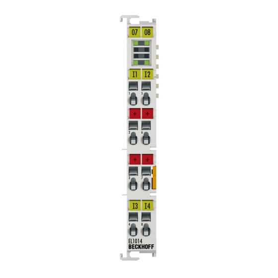
Product overview 2.2.2 EL1014 - LEDs and connection Fig. 14: EL1014 EL1014 - LEDs Color Meaning INPUT 1- 4 green Signal voltage "0" (-3 V ... 5 V) Signal voltage "1" (11 V ... 30 V) EL1014 - Connection Terminal point Description Name Input 1 Input 1 +24 V Sensor supply for input 1 (internally connected to terminal points 3, 6, 7 and positive... -
Page 21: El1018 - Leds And Connection
Product overview 2.2.3 EL1018 - LEDs and connection Fig. 15: EL1018 EL1018 - LEDs Color Meaning INPUT 1- 8 green Signal voltage "0" (-3 V ... 5 V) Signal voltage "1" (11 V ... 30 V) EL1018 - Connection Terminal point Description Name Input 1 Input 1 Input 3 Input 3... -
Page 22: El1012, El1014, El1018 - Technical Data
Product overview 2.2.4 EL1012, EL1014, EL1018 - Technical data Technical data EL1012 EL1014 EL1018 Number of imputs Number of simultaneously controllable in- 2 (> +55°C ) 4 (-25°C ... +55°C) 8 (-25°C ... +55°C) puts, depending on the ambient tempera- 2 (> +55°C ) 4 (>... -
Page 23: El1024, El1034 - Introduction
Product overview EL1024, EL1034 - Introduction EL1024 - four-channel digital input terminals 24 V for type 2 sensors EL1034 - four-channel digital input terminals 24 V , potential-free inputs The EL1024 digital input terminal acquires the binary 24 V control signals and transmits them, in an electrically isolated form, to the higher-level automation system. -
Page 24: El1034 - Leds And Connection
Product overview EL1024 - Connection Terminal point Description Name Input 1 Input 1 +24 V Sensor supply for input 1 (internally connected to terminal points 3, 6, 7 and positive power contact) +24 V Sensor supply for input 3 (internally connected to terminal points 2, 6, 7 and positive power contact) Input 3 Input 3 Input 2... -
Page 25: El1024, El1034 - Technical Data
Product overview EL1034 - Connection Terminal point Description Name Input 1 Input 1 GND 1 Ground (GND) 1 GND 3 Ground (GND) 3 Input 3 Input 3 Input 2 Input 2 GND 2 Ground (GND) 2 GND 4 Ground (GND) 4 Input 4 Input 4 2.3.3... -
Page 26: El108X, El109X - Introduction
Product overview EL108x, EL109x - Introduction Four- and eight-channel digital input terminals 24 V , switching to negative potential The EL108x and EL109x digital input terminals acquire the binary control signals from the process level and transmit them, in an electrically isolated form, to the higher-level automation device. The EL108x and EL109x versions have input filters of different speeds. -
Page 27: El1088, El1098 - Leds And Connection
Product overview 2.4.2 EL1088, EL1098 - LEDs and connection Fig. 19: EL1088, EL1098 EL1088, EL1098 - LEDs Color Meaning INPUT 1- 8 green Signal voltage "0" (18 V ... 30 V) Signal voltage "1" (0 V ... 7 V) EL1088, EL1098 - Connection Terminal point Description Name Input 1... -
Page 28: El1084, El1088, El1094, El1098 - Technical Data
Product overview 2.4.3 EL1084, EL1088, EL1094, EL1098 - Technical data Technical data EL1084 EL1088 EL1094 EL1098 Number of inputs Nominal voltage of the inputs 24 V (-15% / +20%) Signal voltage "0" 18 V ... 30 V Signal voltage "1" 0 V ... 7 V Input filter 3 ms 3 ms 10 µs... -
Page 29: El1104, El1114 - Introduction
Product overview EL1104, EL1114 - Introduction Four-channel digital input terminals 24 V with sensor supply The EL1104 and EL1114 digital input terminals acquire the binary control signals from the process level and transmit them, in an electrically isolated form, to the higher-level automation unit. The EL1104 and EL1114 versions have input filters of different speeds. -
Page 30: El1104, El1114 - Technical Data
Product overview 2.5.2 EL1104, EL1114 - Technical data Technical data EL1104 EL1114 Number of inputs Number of simultaneously controllable inputs, de- 4 (-25°C ... +55°C) 4 (0°C ... + 55°C) pending on the ambient temperature 2 (> +55°C ) Nominal voltage of the inputs 24 V (-15% / +20%) Signal voltage "0"... -
Page 31: El1124, El1144, El1134 - Introduction
Product overview EL1124, EL1144, EL1134 - Introduction Four-channel digital input terminals + 5 / 12 / 48 V The EL1124 (5 V ), EL1144 (12 V ) and EL1134 (48 V ) digital input terminals acquire the binary control signals and transmit them, in an electrically isolated form, to the higher-level automation unit. The EtherCAT Terminals contain four channels that indicate their signal state by means of light emitting diodes. -
Page 32: El1124, El1144, El1134 - Technical Data
Product overview 2.6.2 EL1124, EL1144, EL1134 - Technical data Technical data EL1124 EL1144 EL1134 Number of inputs Nominal voltage of inputs 5 V 12 V 48 V Signal voltage "0" < 0.8 V < 2.4 V -3…5 V (IEC 61131-2, type 1) Signal voltage "1" >2.4 V >... -
Page 33: Application Notes
Product overview Application notes General note To ensure proper function of the input circuit, the power voltage is required for the following series: Power voltage 24 V • EL100x • EL101x • EL1104, EL1114 • EL18xx Power voltage 5 V • EL1124 Notes for EL1x1x series (10 µs typ.) Application for frequency measurement Due to their fast input filters (typ. -
Page 34: Basics Communication
EtherCAT devices from Beckhoff. Recommended cables Suitable cables for the connection of EtherCAT devices can be found on the Beckhoff website! E-Bus supply A bus coupler can supply the EL terminals added to it with the E-bus system voltage of 5 V; a coupler is thereby loadable up to 2 A as a rule (see details in respective device documentation). -
Page 35: General Notes For Setting The Watchdog
Basics communication Fig. 22: System manager current calculation NOTE Malfunction possible! The same ground potential must be used for the E-Bus supply of all EtherCAT terminals in a terminal block! General notes for setting the watchdog ELxxxx terminals are equipped with a safety feature (watchdog) that switches off the outputs after a specifiable time e.g. -
Page 36: Fig. 23 Ethercat Tab -> Advanced Settings -> Behavior -> Watchdog
Basics communication Fig. 23: EtherCAT tab -> Advanced Settings -> Behavior -> Watchdog Notes: • the multiplier is valid for both watchdogs. • each watchdog has its own timer setting, the outcome of this in summary with the multiplier is a resulting time. -
Page 37: Ethercat State Machine
Basics communication Example "Set SM watchdog" This checkbox enables manual setting of the watchdog times. If the outputs are set and the EtherCAT communication is interrupted, the SM watchdog is triggered after the set time and the outputs are erased. This setting can be used for adapting a terminal to a slower EtherCAT master or long cycle times. -
Page 38: Fig. 24 States Of The Ethercat State Machine
Basics communication Fig. 24: States of the EtherCAT State Machine Init After switch-on the EtherCAT slave in the Init state. No mailbox or process data communication is possible. The EtherCAT master initializes sync manager channels 0 and 1 for mailbox communication. Pre-Operational (Pre-Op) During the transition between Init and Pre-Op the EtherCAT slave checks whether the mailbox was initialized correctly. -
Page 39: Coe - Interface: Notes
In the Boot state mailbox communication via the file access over EtherCAT (FoE) protocol is possible, but no other mailbox communication and no process data communication. CoE - Interface: notes This device has no CoE. Detailed information on the CoE interface can be found in the EtherCAT system documentation on the Beckhoff website. EL10xx, EL11xx Version: 4.5... -
Page 40: Distributed Clock
Basics communication Distributed Clock The distributed clock represents a local clock in the EtherCAT slave controller (ESC) with the following characteristics: • Unit 1 ns • Zero point 1.1.2000 00:00 • Size 64 bit (sufficient for the next 584 years; however, some EtherCAT slaves only offer 32-bit support, i.e. -
Page 41: Mounting And Wiring
• Each assembly must be terminated at the right hand end with an EL9011 or EL9012 bus end cap, to en- sure the protection class and ESD protection. Fig. 25: Spring contacts of the Beckhoff I/O components Installation on mounting rails... -
Page 42: Fig. 26 Attaching On Mounting Rail
Mounting and wiring Assembly Fig. 26: Attaching on mounting rail The bus coupler and bus terminals are attached to commercially available 35 mm mounting rails (DIN rails according to EN 60715) by applying slight pressure: 1. First attach the fieldbus coupler to the mounting rail. 2. -
Page 43: Fig. 27 Disassembling Of Terminal
Mounting and wiring Disassembly Fig. 27: Disassembling of terminal Each terminal is secured by a lock on the mounting rail, which must be released for disassembly: 1. Pull the terminal by its orange-colored lugs approximately 1 cm away from the mounting rail. In doing so for this terminal the mounting rail lock is released automatically and you can pull the terminal out of the bus terminal block easily without excessive force. -
Page 44: Installation Positions
Mounting and wiring Fig. 28: Power contact on left side NOTE Possible damage of the device Note that, for reasons of electromagnetic compatibility, the PE contacts are capacitatively coupled to the mounting rail. This may lead to incorrect results during insulation testing or to damage on the terminal (e.g. disruptive discharge to the PE line during insulation testing of a consumer with a nominal voltage of 230 V). -
Page 45: Fig. 29 Recommended Distances For Standard Installation Position
Mounting and wiring Fig. 29: Recommended distances for standard installation position Compliance with the distances shown in Fig. “Recommended distances for standard installation position” is recommended. Other installation positions All other installation positions are characterized by different spatial arrangement of the mounting rail - see Fig “Other installation positions”. -
Page 46: Installation Instructions For Enhanced Mechanical Load Capacity
Mounting and wiring Fig. 30: Other installation positions Installation instructions for enhanced mechanical load capacity WARNING Risk of injury through electric shock and damage to the device! Bring the Bus Terminal system into a safe, de-energized state before starting mounting, disassembly or wiring of the Bus Terminals! Additional checks The terminals have undergone the following additional tests:... -
Page 47: Positioning Of Passive Terminals
Mounting and wiring Positioning of passive Terminals Hint for positioning of passive terminals in the bus terminal block EtherCAT Terminals (ELxxxx / ESxxxx), which do not take an active part in data transfer within the bus terminal block are so called passive terminals. The passive terminals have no current consump- tion out of the E-Bus. -
Page 48: Fig. 33 Standard Wiring
Mounting and wiring Overview The Bus Terminal system offers different connection options for optimum adaptation to the respective application: • The terminals of ELxxxx and KLxxxx series with standard wiring include electronics and connection level in a single enclosure. • The terminals of ESxxxx and KSxxxx series feature a pluggable connection level and enable steady wiring while replacing. -
Page 49: Fig. 35 High Density Terminals
Mounting and wiring High Density Terminals (HD Terminals) Fig. 35: High Density Terminals The Bus Terminals from these series with 16 terminal points are distinguished by a particularly compact design, as the packaging density is twice as large as that of the standard 12 mm Bus Terminals. Massive conductors and conductors with a wire end sleeve can be inserted directly into the spring loaded terminal point without tools. -
Page 50: Wiring
Mounting and wiring 4.6.2 Wiring WARNING Risk of electric shock and damage of device! Bring the bus terminal system into a safe, powered down state before starting installation, disassembly or wiring of the Bus Terminals! Terminals for standard wiring ELxxxx/KLxxxx and for pluggable wiring ESxxxx/KSxxxx Fig. 36: Connecting a cable on a terminal point Up to eight terminal points enable the connection of solid or finely stranded cables to the Bus Terminal. -
Page 51: Shielding
80°C at the wire branching points, then cables must be selected whose tempera- ture data correspond to the actual measured temperature values! • Observe the permissible ambient temperature range of 0 to 55°C for the use of Beckhoff fieldbus compo- nents standard temperature range in potentially explosive areas! •... -
Page 52: Atex - Special Conditions (Extended Temperature Range)
80°C at the wire branching points, then cables must be selected whose tempera- ture data correspond to the actual measured temperature values! • Observe the permissible ambient temperature range of -25 to 60°C for the use of Beckhoff fieldbus com- ponents with extended temperature range (ET) in potentially explosive areas! •... -
Page 53: Atex Documentation
Beckhoff EtherCAT modules are intended for use with Beckhoff’s UL Listed EtherCAT Sys- tem only. Examination For cULus examination, the Beckhoff I/O System has only been investigated for risk of fire and electrical shock (in accordance with UL508 and CSA C22.2 No. 142). For devices with Ethernet connectors Not for connection to telecommunication circuits. -
Page 54: Commissioning
5.1.1 Installation of the TwinCAT real-time driver In order to assign real-time capability to a standard Ethernet port of an IPC controller, the Beckhoff real-time driver has to be installed on this port under Windows. This can be done in several ways. One option is described here. -
Page 55: Fig. 37 System Manager "Options" (Twincat 2)
Commissioning Fig. 37: System Manager “Options” (TwinCAT 2) This have to be called up by the Menü “TwinCAT” within the TwinCAT 3 environment: Fig. 38: Call up under VS Shell (TwinCAT 3) The following dialog appears: Fig. 39: Overview of network interfaces Interfaces listed under “Compatible devices” can be assigned a driver via the “Install” button. A driver should only be installed on compatible devices. -
Page 56: Fig. 40 Ethercat Device Properties(Twincat 2): Click On „Compatible Devices
Commissioning Fig. 40: EtherCAT device properties(TwinCAT 2): click on „Compatible Devices…“ of tab “Adapter” TwinCAT 3: the properties of the EtherCAT device can be opened by double click on “Device .. (EtherCAT)” within the Solution Explorer under “I/O”: After the installation the driver appears activated in the Windows overview for the network interface (Windows Start →... - Page 57 Commissioning Fig. 42: Exemplary correct driver setting for the Ethernet port Other possible settings have to be avoided: EL10xx, EL11xx Version: 4.5...
- Page 58 Commissioning Fig. 43: Incorrect driver settings for the Ethernet port Version: 4.5 EL10xx, EL11xx...
- Page 59 Commissioning IP address of the port used IP address/DHCP In most cases an Ethernet port that is configured as an EtherCAT device will not transport general IP packets. For this reason and in cases where an EL6601 or similar devices are used it is useful to specify a fixed IP address for this port via the “Internet Protocol TCP/IP”...
-
Page 60: Notes Regarding Esi Device Description
The files are read (once) when a new System Manager window is opened, if they have changed since the last time the System Manager window was opened. A TwinCAT installation includes the set of Beckhoff ESI files that was current at the time when the TwinCAT build was created. - Page 61 1018 in the configuration. This is also stated by the Beckhoff compatibility rule. Refer in particular to the chapter ‘General notes on the use of Beckhoff EtherCAT IO components’ and for manual configuration to the chapter ‘Offline configuration creation’ [} 64].
- Page 62 Commissioning Fig. 48: File OnlineDescription.xml created by the System Manager Is a slave desired to be added manually to the configuration at a later stage, online created slaves are indicated by a prepended symbol “>” in the selection list (see Figure “Indication of an online recorded ESI of EL2521 as an example”).
- Page 63 Commissioning Reasons may include: • Structure of the *.xml does not correspond to the associated *.xsd file → check your schematics • Contents cannot be translated into a device description → contact the file manufacturer EL10xx, EL11xx Version: 4.5...
-
Page 64: Offline Configuration Creation
Commissioning 5.1.3 OFFLINE configuration creation Creating the EtherCAT device Create an EtherCAT device in an empty System Manager window. Fig. 51: Append EtherCAT device (left: TwinCAT 2; right: TwinCAT 3) Select type ‘EtherCAT’ for an EtherCAT I/O application with EtherCAT slaves. For the present publisher/ subscriber service in combination with an EL6601/EL6614 terminal select “EtherCAT Automation Protocol via EL6601”. - Page 65 Commissioning Fig. 54: EtherCAT device properties (TwinCAT 2) TwinCAT 3: the properties of the EtherCAT device can be opened by double click on “Device .. (EtherCAT)” within the Solution Explorer under “I/O”: Selecting the Ethernet port Ethernet ports can only be selected for EtherCAT devices for which the TwinCAT real-time driver is installed.
- Page 66 (i.e. highest) revision and therefore the latest state of production is displayed in the selection dialog for Beckhoff devices. To show all device revisions available in the system as ESI descriptions tick the “Show Hidden Devices” check box, see Fig. “Display of previous revisions”.
- Page 67 If current ESI descriptions are available in the TwinCAT system, the last revision offered in the selection dialog matches the Beckhoff state of production. It is recommended to use the last device revision when creating a new configuration, if current Beckhoff devices are used in the real application. Older revisions should only be used if older devices from stock are to be used in the application.
- Page 68 Commissioning Fig. 60: EtherCAT terminal in the TwinCAT tree (left: TwinCAT 2; right: TwinCAT 3) Version: 4.5 EL10xx, EL11xx...
-
Page 69: Online Configuration Creation
Commissioning 5.1.4 ONLINE configuration creation Detecting/scanning of the EtherCAT device The online device search can be used if the TwinCAT system is in CONFIG mode. This can be indicated by a symbol right below in the information bar: • on TwinCAT 2 by a blue display “Config Mode” within the System Manager window: •... - Page 70 [} 74] with the defined initial configuration.Background: since Beckhoff occasionally increases the revision version of the delivered products for product maintenance reasons, a configuration can be created by such a scan which (with an identical machine construction) is identical according to the device list;...
- Page 71 Likewise, A might create spare parts stores worldwide for the coming series-produced machines with EL2521-0025-1018 terminals. After some time Beckhoff extends the EL2521-0025 by a new feature C. Therefore the FW is changed, outwardly recognizable by a higher FW version and a new revision -1019. Nevertheless the new device naturally supports functions and interfaces of the predecessor version(s);...
- Page 72 Commissioning Fig. 69: Manual triggering of a device scan on a specified EtherCAT device (left: TwinCAT 2; right: TwinCAT 3) In the System Manager (TwinCAT 2) or the User Interface (TwinCAT 3) the scan process can be monitored via the progress bar at the bottom in the status bar. Fig. 70: Scan progressexemplary by TwinCAT 2 The configuration is established and can then be switched to online state (OPERATIONAL).
- Page 73 Commissioning Fig. 74: Online display example Please note: • all slaves should be in OP state • the EtherCAT master should be in “Actual State” OP • “frames/sec” should match the cycle time taking into account the sent number of frames •...
- Page 74 A ‘ChangeTo’ or ‘Copy’ should only be carried out with care, taking into consideration the Beckhoff IO compatibility rule (see above). The device configuration is then replaced by the revision found; this can affect the supported process data and functions.
- Page 75 If current ESI descriptions are available in the TwinCAT system, the last revision offered in the selection dialog matches the Beckhoff state of production. It is recommended to use the last device revision when creating a new configuration, if current Beckhoff devices are used in the real application. Older revisions should only be used if older devices from stock are to be used in the application.
- Page 76 Commissioning Fig. 79: Correction dialog with modifications Once all modifications have been saved or accepted, click “OK” to transfer them to the real *.tsm configuration. Change to Compatible Type TwinCAT offers a function “Change to Compatible Type…” for the exchange of a device whilst retaining the links in the task.
-
Page 77: Ethercat Slave Process Data Settings
To this end the EtherCAT master (Beckhoff TwinCAT) parameterizes each EtherCAT slave during the start-up phase to define which process data (size in bits/bytes, source location, transmission type) it wants to transfer to or from this slave. -
Page 78: Configuration With The Twincat System Manager - Digital Input And Output Terminals
Commissioning Fig. 82: Configuring the process data Manual modification of the process data According to the ESI description, a PDO can be identified as “fixed” with the flag “F” in the PDO overview (Fig. “Configuring the process data”, J). The configuration of such PDOs cannot be changed, even if TwinCAT offers the associated dialog (“Edit”). - Page 79 Commissioning General tab Fig. 83: General tab Name Name of the EtherCAT device Number of the EtherCAT device Type EtherCAT device type Comment Here you can add a comment (e.g. regarding the system). Disabled Here you can deactivate the EtherCAT device. Create symbols Access to this EtherCAT slave via ADS is only available if this control box is activated.
- Page 80 Commissioning Type EtherCAT device type Product/Revision Product and revision number of the EtherCAT device Auto Inc Addr. Auto increment address of the EtherCAT device. The auto increment address can be used for addressing each EtherCAT device in the communication ring through its physical position.
- Page 81 Commissioning PDO Assignment PDO assignment of the selected Sync Manager. All PDOs defined for this Sync Manager type are listed here. The selected entries are the PDOs involved in the process data transfer. In the tree diagram of the System Manager these PDOs are displayed as variables of the EtherCAT device.
- Page 82 Commissioning Online tab Fig. 86: Online tab State Machine Init This button attempts to set the EtherCAT device to the Init state. Pre-Op This button attempts to set the EtherCAT device to the pre-operational state. This button attempts to set the EtherCAT device to the operational state. Bootstrap This button attempts to set the EtherCAT device to the Bootstrap state.
-
Page 83: General Notes - Ethercat Slave Application
Commissioning General Notes - EtherCAT Slave Application This summary briefly deals with a number of aspects of EtherCAT Slave operation under TwinCAT. More detailed information on this may be found in the corresponding sections of, for instance, the EtherCAT System Documentation. Diagnosis in real time: WorkingCounter, EtherCAT State and Status Generally speaking an EtherCAT Slave provides a variety of diagnostic information that can be used by the controlling task. - Page 84 Fig. “Basic EtherCAT Slave Diagnosis in the PLC” shows an example of an implementation of basic EtherCAT Slave Diagnosis. A Beckhoff EL3102 (2-channel analogue input terminal) is used here, as it offers both the communication diagnosis typical of a slave and the functional diagnosis that is specific to a channel.
- Page 85 Commissioning Code Function Implementation Application/evaluation The EtherCAT Master's diagnostic infor- At least the DevState is to be evaluated for mation the most recent cycle in the PLC. updated acyclically (yellow) or provided The EtherCAT Master's diagnostic informa- acyclically (green). tion offers many more possibilities than are treated in the EtherCAT System Documenta- tion.
- Page 86 Commissioning Fig. 89: EL3102, CoE directory EtherCAT System Documentation The comprehensive description in the EtherCAT System Documentation (EtherCAT Basics --> CoE Interface) must be observed! A few brief extracts: • Whether changes in the online directory are saved locally in the slave depends on the device. EL terminals (except the EL66xx) are able to save in this way.
- Page 87 Commissioning Fig. 90: Example of commissioning aid for a EL3204 This commissioning process simultaneously manages • CoE Parameter Directory • DC/FreeRun mode • the available process data records (PDO) Although the "Process Data", "DC", "Startup" and "CoE-Online" that used to be necessary for this are still displayed, it is recommended that, if the commissioning aid is used, the automatically generated settings are not changed by it.
- Page 88 Commissioning Standard setting The advanced settings of the EtherCAT Master are set as standard: • EtherCAT Master: OP • Slaves: OP This setting applies equally to all Slaves. Fig. 91: Default behaviour of the System Manager In addition, the target state of any particular Slave can be set in the "Advanced Settings" dialogue; the standard setting is again OP.
- Page 89 Commissioning Manual Control There are particular reasons why it may be appropriate to control the states from the application/task/PLC. For instance: • for diagnostic reasons • to induce a controlled restart of axes • because a change in the times involved in starting is desirable In that case it is appropriate in the PLC application to use the PLC function blocks from the TcEtherCAT.lib, which is available as standard, and to work through the states in a controlled manner using, for instance, FB_EcSetMasterState.
- Page 90 Commissioning Fig. 94: Illegally exceeding the E-Bus current From TwinCAT 2.11 and above, a warning message "E-Bus Power of Terminal..." is output in the logger window when such a configuration is activated: Fig. 95: Warning message for exceeding E-Bus current NOTE Caution! Malfunction possible! The same ground potential must be used for the E-Bus supply of all EtherCAT terminals in a terminal block! Version: 4.5 EL10xx, EL11xx...
-
Page 91: Control And Status Byte
Commissioning Control and Status Byte Control byte The control byte of the digital input terminals currently has no function. Status byte The status byte of the digital input terminals currently has no function. EL10xx, EL11xx Version: 4.5... -
Page 92: Appendix
The terminals of the EL10xx and EL11xx series have no firmware. Firmware Update EL/ES/EM/ELM/EPxxxx This section describes the device update for Beckhoff EtherCAT slaves from the EL/ES, ELM, EM, EK and EP series. A firmware update should only be carried out after consultation with Beckhoff support. -
Page 93: Device Description Esi File/Xml
The device revision is closely linked to the firmware and hardware used. Incompatible combinations lead to malfunctions or even final shutdown of the device. Corresponding updates should only be carried out in consultation with Beckhoff support. Display of ESI slave identifier... - Page 94 Appendix Fig. 97: Scan the subordinate field by right-clicking on the EtherCAT device If the found field matches the configured field, the display shows Fig. 98: Configuration is identical otherwise a change dialog appears for entering the actual data in the configuration. Fig. 99: Change dialog In this example in Fig.
- Page 95 Appendix Changing the ESI slave identifier The ESI/EEPROM identifier can be updated as follows under TwinCAT: • Trouble-free EtherCAT communication must be established with the slave. • The state of the slave is irrelevant. • Right-clicking on the slave in the online display opens the EEPROM Update dialog, Fig. EEPROM Update Fig. 100: EEPROM Update The new ESI description is selected in the following dialog, see Fig.
-
Page 96: Firmware Explanation
• offline: The EtherCAT Slave Information ESI/XML may contain the default content of the CoE. This CoE directory can only be displayed if it is included in the ESI (e.g. "Beckhoff EL5xxx.xml"). The Advanced button must be used for switching between the two views. -
Page 97: Updating Controller Firmware *.Efw
Switch to the Online tab to update the controller firmware of a slave, see Fig. Firmware Update. Fig. 103: Firmware Update Proceed as follows, unless instructed otherwise by Beckhoff support. Valid for TwinCAT 2 and 3 as EtherCAT master. • Switch TwinCAT system to ConfigMode/FreeRun with cycle time >= 1 ms (default in ConfigMode is 4 ms). -
Page 98: Fpga Firmware *.Rbf
Appendix • Switch EtherCAT Master to PreOP • Switch slave to INIT (A) • Switch slave to BOOTSTRAP • Check the current status (B, C) • Download the new *efw file (wait until it ends). A pass word will not be neccessary usually. •... - Page 99 Appendix Fig. 104: FPGA firmware version definition If the column Reg:0002 is not displayed, right-click the table header and select Properties in the context menu. Fig. 105: Context menu Properties The Advanced Settings dialog appears where the columns to be displayed can be selected. Under Diagnosis/Online View select the '0002 ETxxxx Build' check box in order to activate the FPGA firmware version display.
- Page 100 Older firmware versions can only be updated by the manufacturer! Updating an EtherCAT device The following sequence order have to be met if no other specifications are given (e.g. by the Beckhoff support): • Switch TwinCAT system to ConfigMode/FreeRun with cycle time >= 1 ms (default in ConfigMode is 4 ms).
- Page 101 Appendix • In the TwinCAT System Manager select the terminal for which the FPGA firmware is to be updated (in the example: Terminal 5: EL5001) and click the Advanced Settings button in the EtherCAT tab: • The Advanced Settings dialog appears. Under ESC Access/E²PROM/FPGA click on Write FPGA button: EL10xx, EL11xx Version: 4.5...
-
Page 102: Simultaneous Updating Of Several Ethercat Devices
Appendix • Select the file (*.rbf) with the new FPGA firmware, and transfer it to the EtherCAT device: • Wait until download ends • Switch slave current less for a short time (don't pull under voltage!). In order to activate the new FPGA firmware a restart (switching the power supply off and on again) of the EtherCAT device is required. -
Page 103: Support And Service
Beckhoff's branch offices and representatives Please contact your Beckhoff branch office or representative for local support and service on Beckhoff products! The addresses of Beckhoff's branch offices and representatives round the world can be found on her internet pages: http://www.beckhoff.com You will also find further documentation for Beckhoff components there. - Page 104 Fig. 23 EtherCAT tab -> Advanced Settings -> Behavior -> Watchdog ..........Fig. 24 States of the EtherCAT State Machine..................Fig. 25 Spring contacts of the Beckhoff I/O components................. Fig. 26 Attaching on mounting rail ......................Fig. 27 Disassembling of terminal......................
- Page 105 List of illustrations Fig. 42 Exemplary correct driver setting for the Ethernet port ..............Fig. 43 Incorrect driver settings for the Ethernet port ................Fig. 44 TCP/IP setting for the Ethernet port .................... Fig. 45 Identifier structure ........................Fig. 46 OnlineDescription information window (TwinCAT 2) ..............
- Page 106 List of illustrations Fig. 86 Online tab ............................ Fig. 87 Selection of the diagnostic information of an EtherCAT Slave ........... Fig. 88 Basic EtherCAT Slave Diagnosis in the PLC................Fig. 89 EL3102, CoE directory ........................ Fig. 90 Example of commissioning aid for a EL3204 ................Fig.
Need help?
Do you have a question about the EL10 Series and is the answer not in the manual?
Questions and answers