Sign In
Upload
Download
Table of Contents
Contents
Add to my manuals
Delete from my manuals
Share
URL of this page:
HTML Link:
Bookmark this page
Add
Manual will be automatically added to "My Manuals"
Print this page
×
Bookmark added
×
Added to my manuals
Manuals
Brands
Beckhoff Manuals
Touch terminals
EL34 Series
Documentation
Beckhoff EL34 Series Documentation
3-phase energy and power measurement terminals
Hide thumbs
1
2
3
4
5
6
7
8
9
10
11
12
13
14
15
16
17
18
19
20
21
22
23
24
25
26
27
28
29
30
31
32
33
34
35
36
37
38
39
40
41
42
43
44
45
46
47
48
49
50
51
52
53
54
55
56
57
58
59
60
61
62
63
64
65
66
67
68
69
70
71
72
73
74
75
76
77
78
79
80
81
82
83
84
85
86
87
88
89
90
91
92
93
94
95
96
97
98
99
100
101
102
103
104
105
106
107
108
109
110
111
112
113
114
115
116
117
118
119
120
121
122
123
124
125
126
127
128
129
130
131
132
133
134
135
136
137
138
139
140
141
142
143
144
145
146
147
148
149
150
151
152
153
154
155
156
157
158
159
160
161
162
163
164
165
166
167
168
169
170
171
172
173
174
175
176
177
178
179
180
181
182
183
184
185
186
187
188
189
190
191
192
193
194
195
196
197
198
199
200
201
202
203
204
205
206
207
208
209
210
211
212
213
214
215
216
217
218
219
220
221
222
223
224
225
226
227
228
229
230
231
232
233
234
235
236
237
238
239
240
241
242
243
244
245
246
247
248
249
250
251
252
253
254
255
256
257
258
259
260
261
262
263
264
265
266
267
268
269
270
271
272
273
274
275
276
277
278
279
280
281
282
283
284
285
286
287
288
289
290
291
292
293
294
295
page
of
295
Go
/
295
Contents
Table of Contents
Bookmarks
Table of Contents
Table of Contents
1 Product Overview - Power Measurement Terminals
2 Foreword
Notes on the Documentation
Safety Instructions
Documentation Issue Status
Version Identification of Ethercat Devices
Fig. 1 EL5021 el Terminal, Standard IP20 IO Device with Serial/ Batch Number and Revision ID (Since 2014/01)
Fig. 2 EK1100 Ethercat Coupler, Standard IP20 IO Device with Serial/ Batch Number
Fig. 3 CU2016 Switch with Serial/ Batch Number
Fig. 4 EL3202-0020 with Serial/ Batch Number 26131006 and Unique ID-Number 204418
Fig. 5 EP1258-00001 IP67 Ethercat Box with Batch Number/ Date Code 22090101 and Unique Se- Rial Number 158102
Fig. 6 EP1908-0002 IP67 Ethercat Safety Box with Batch Number/ Date Code 071201FF and Unique Serial Number 00346070
Fig. 7 EL2904 IP20 Safety Terminal with Batch Number/ Date Code 50110302 and Unique Serial Num- Ber 00331701
Fig. 8 ELM3604-0002 Terminal with Unique ID Number (QR Code) 100001051 and Serial/ Batch Num- Ber 44160201
Beckhoff Identification Code (BIC)
Fig. 9 BIC as Data Matrix Code (DMC, Code Scheme ECC200)
3 Product Overview
El34Xx - Introduction
Fig. 12 EL3483
Technical Data
Fig. 13 EL3453
Basic Function Principles
Fig. 14 Voltage U and Current I Curves
Fig. 17 Four-Quadrant Representation of Active Power/Fundamental Harmonic Reactive Power in Motor and Generator Mode
Current Transformers
Start
4 Basics Communication
Ethercat Basics
Ethercat Cabling - Wire-Bound
General Notes for Setting the Watchdog
Ethercat State Machine
Coe Interface
Distributed Clock
5 Mounting and Wiring
Instructions for ESD Protection
Installation on Mounting Rails
Connection
Connection System
Wiring
Shielding
Installation Positions
Positioning of Passive Terminals
El34Xx - Leds and Connection
6 Commissioning
Twincat Quick Start
Twincat 2
Twincat 3
Twincat Development Environment
Installation of the Twincat Real-Time Driver
Notes Regarding ESI Device Description
Twincat ESI Updater
Distinction between Online and Offline
OFFLINE Configuration Creation
ONLINE Configuration Creation
Ethercat Subscriber Configuration
General Notes - Ethercat Slave Application
Process Data
Sync Manager
Settings
Timestamp Distributed Clocks
Scaling Factors
Notices on Analog Specifications
Full Scale Value (FSV)
Measuring Error/ Measurement Deviation
Temperature Coefficient Tk [Ppm/K]
Single-Ended/Differential Typification
Common-Mode Voltage and Reference Ground (Based on Differential Inputs)
Dielectric Strength
Temporal Aspects of Analog/Digital Conversion
Object Description and Parameterization
Restore Object
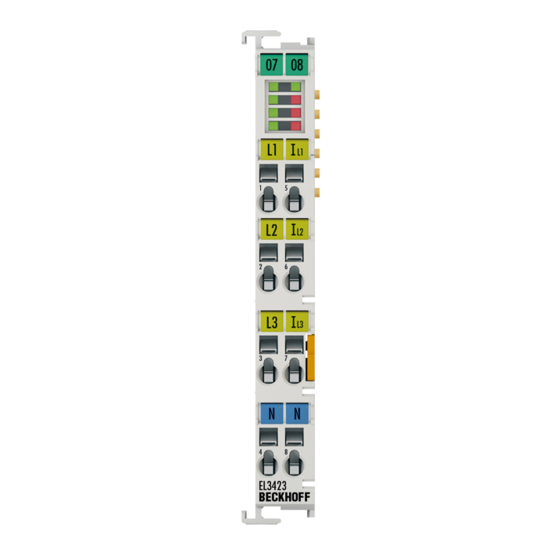
El3423
EL3443-00Xx
El3453
Fig. 10 EL3443
EL3483-00Xx
7 Application Examples
Power Measurement on Motor with 2 or 3 Current Transformers
Power Measurement at a Machine
Power Measurement in a Single-Phase Mains Network with Ohmic Consumers
Power Measurement at a Fieldbus Station
Power Measurement at Three-Phase Motors Controlled by a Frequency Converter
Power Measurement Including Differential Current Measurement
Example Function Blocks for Evaluation
8 Appendix
Tceventlogger and IO
Ethercat al Status Codes
Firmware Compatibility
Fig. 11 EL3423
Firmware Update El/Es/Em/Elm/Epxxxx
Device Description ESI File/Xml
Firmware Explanation
Updating Controller Firmware *.Efw
FPGA Firmware *.Rbf
Simultaneous Updating of Several Ethercat Devices
Restoring the Delivery State
Support and Service
List of Illustrations
Advertisement
Quick Links
1
El34Xx - Introduction
2
Fig. 13 El3453
3
El3443-00Xx
4
El3453
5
Power Measurement on Motor with 2 or 3 Current Transformers
Download this manual
Documentation
EL34xx
3-phase energy and power measurement terminals
Version:
Date:
1.5
2019-09-05
Table of
Contents
Previous
Page
Next
Page
1
2
3
4
5
Advertisement
Chapters
Table of Contents
3
List of Illustrations
291
Table of Contents
Need help?
Do you have a question about the EL34 Series and is the answer not in the manual?
Ask a question
Questions and answers
Related Manuals for Beckhoff EL34 Series
Touch terminals beckhoff EL3101 Documentation
El31xx-00xx series analog input terminals (229 pages)
Touch terminals BECKHOFF EL3702 Documentation
El37x2 series analog input terminals with oversampling (181 pages)
Touch terminals Beckhoff EL34x3 Series Documentation
3-phase power measurement terminal (200 pages)
Touch terminals Beckhoff EL3433 Documentation
3-phase power measurement terminal (200 pages)
Touch terminals Beckhoff EL3423 Documentation
3-phase energy and power measurement terminals (295 pages)
Touch terminals Beckhoff EL3453 Documentation
3-phase energy and power measurement terminals (295 pages)
Touch terminals Beckhoff EL3483 Documentation
3-phase energy and power measurement terminals (295 pages)
Touch terminals Beckhoff EL3443 Documentation
3-phase energy and power measurement terminals (295 pages)
Touch terminals Beckhoff EL3773 Documentation
Power monitoring oversampling terminal (179 pages)
Touch terminals Beckhoff EL3632 Documentation
2 channel analog input terminal for condition monitoring (iepe) (214 pages)
Touch terminals Beckhoff EL3182 Documentation
2 channel analog input teminal (4...20 ma), single-ended, 16 bit, hart (145 pages)
Touch terminals Beckhoff EL3783 Documentation
Power monitoring oversampling terminal for 690 v (188 pages)
Touch terminals Beckhoff EL6910 Operation Manual
Twinsafe logic terminal (105 pages)
Touch terminals Beckhoff EL6601 Documentation
Switch terminals for ethernet (163 pages)
Touch terminals Beckhoff EL6692 Documentation
Ethercat bridge terminal (156 pages)
Touch terminals Beckhoff EL2904 Operating Instructions Manual
Twinsafe terminal with 4 digital fail-safe outputs (51 pages)
This manual is also suitable for:
El3423
El3443-0013
El3453
El3483
El3483-0060
El3443
...
Show all
El3443-0010
El3443-0011
Table of Contents
Print
Rename the bookmark
Delete bookmark?
Delete from my manuals?
Login
Sign In
OR
Sign in with Facebook
Sign in with Google
Upload manual
Upload from disk
Upload from URL


Need help?
Do you have a question about the EL34 Series and is the answer not in the manual?
Questions and answers