
Subscribe to Our Youtube Channel
Related Manuals for Beckhoff ELX3202


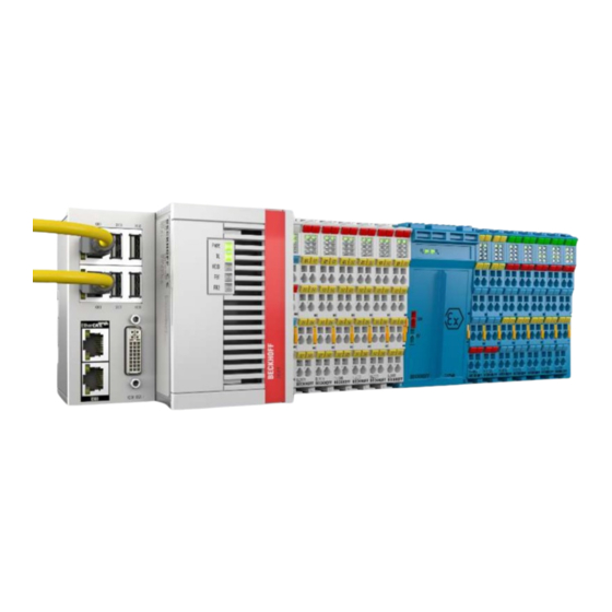
Summary of Contents for Beckhoff ELX3202
- Page 1 Operating manual ELX3202 and ELX3204 2- and 4-channel analog input terminals, RTD, 16 bit, Ex i Version: 1.4.0 Date: 2019-09-26...
-
Page 3: Table Of Contents
Notes on the documentation...................... 5 Safety instructions .......................... 6 Documentation Issue Status...................... 7 Marking of ELX terminals........................ 8 2 Product overview............................. 12 ELX3202 - Introduction ......................... 12 ELX3204 - Introduction ......................... 13 Technical data .......................... 14 Intended use .......................... 15 3 Mounting and wiring .......................... 16 Special conditions of use for ELX terminals ................. - Page 4 Commissioning on the basis of CoE objects ................ 65 Basic information for commissioning .................... 65 Resistance measuring (R/RTD).................... 66 7 Appendix .............................. 68 EtherCAT AL Status Codes ...................... 68 UL notice............................ 68 FM notice ............................ 69 Support and Service ........................ 70 Version: 1.4.0 ELX3202 and ELX3204...
-
Page 5: Foreword
EP1590927, EP1789857, EP1456722, EP2137893, DE102015105702 with corresponding applications or registrations in various other countries. ® EtherCAT is registered trademark and patented technology, licensed by Beckhoff Automation GmbH, Germany. Copyright © Beckhoff Automation GmbH & Co. KG, Germany. The reproduction, distribution and utilization of this document as well as the communication of its contents to others without express authorization are prohibited. -
Page 6: Safety Instructions
All the components are supplied in particular hardware and software configurations appropriate for the application. Modifications to hardware or software configurations other than those described in the documentation are not permitted, and nullify the liability of Beckhoff Automation GmbH & Co. KG. Personnel qualification This description is only intended for trained specialists in control, automation and drive engineering who are familiar with the applicable national standards. -
Page 7: Documentation Issue Status
• Chapter Arrangement of ELX terminals at the bus terminal updated 1.0.1 • Layout updated • Chapter Mounting and wiring updated • Technical data updated • Chapter Mounting and wiring updated • Chapter Intended use added • First preliminary version ELX3202 and ELX3204 Version: 1.4.0... -
Page 8: Marking Of Elx Terminals
• Beckhoff Traceability Number, or BTN for short (as a serial number it clearly identifies each terminal) Date code The date code is an eight-digit number given by Beckhoff and printed on the ELX terminal. The date code indicates the build version in the delivery state and thus identifies an entire production batch, but does not distinguish between the terminals in a batch. -
Page 9: Fig. 1 Elx2008-0000 With Date Code 2519Hmhm, Btn 0001F6Hd And Ex Marking
01 - firmware version 01 00 - hardware version 00 Beckhoff Traceability Number (BTN) In addition, each ELX terminal has a unique Beckhoff Traceability Number (BTN). Ex marking The Ex marking can be found at the top left on the terminal:... -
Page 10: Fig. 2 Elx9560-0000 With Date Code 12150000, Btn 000B000 And Ex Marking
Foreword Fig. 2: ELX9560-0000 with date code 12150000, BTN 000b000 and Ex marking Version: 1.4.0 ELX3202 and ELX3204... -
Page 11: Fig. 3 Elx9012 With Date Code 12174444, Btn 0000B0Si And Ex Marking
Foreword Fig. 3: ELX9012 with date code 12174444, BTN 0000b0si and Ex marking ELX3202 and ELX3204 Version: 1.4.0... -
Page 12: Product Overview
The ELX3202 analog input terminal allows the direct connection of RTDs located in hazardous areas classified Zone 0/20 or 1/21. The circuitry of the ELX3202 can operate sensors with 2, 3 and 4-wire technology. Linearization is carried out over the entire freely selectable temperature range. By default the terminal is set to PT100 sensors with 2-wire technology. -
Page 13: Elx3204 - Introduction
Linearization is carried out over the entire freely selectable temperature range. By default the terminal is set to PT100 sensors with 2-wire technology. The ELX3204 terminal indicates signal state and sensor malfunctions (e.g. wire breakage) by means of LEDs. ELX3202 and ELX3204 Version: 1.4.0... -
Page 14: Technical Data
Vibration / shock resistance conforms to EN 60068-2-6 / EN 60068-2-27 EMC immunity / emission conforms to EN 61000-6-2 / EN 61000-6-4 Protect. class IP20 Permissible installation position See chapter Installation position and minimum distances [} 21] Approvals / markings CE, UL, ATEX, IECEx, cFMus Version: 1.4.0 ELX3202 and ELX3204... -
Page 15: Intended Use
IECEx scheme! CAUTION The ELX terminals extend the field of application of the Beckhoff bus terminal system with functions for integrating intrinsically safe field devices from hazardous areas. The intended field of application is data acquisition and control tasks in discrete and process engineering automation, taking into account explosion protection requirements. -
Page 16: Mounting And Wiring
• Observe the permissible ambient temperature range of -25 to +60°C of Beckhoff ELX terminals! • Measures must be taken to protect against the rated operating voltage being exceeded by more than 40% due to short-term interference voltages! The power supply of the ELX9560 power supply terminal must correspond to overvoltage category II according... - Page 17 1 to 8 on the left above the respective terminal point as well as via the laser image. Observe any possible polarity dependency of connected intrinsically safe circuits! ELX3202 and ELX3204 Version: 1.4.0...
-
Page 18: Arrangement Of Elx Terminals Within A Bus Terminal Block
• The last terminal of each ELX segment is to be covered by an ELX9012 bus end cover, unless two ELX9410 power supply terminals are installed in direct succession for con- tinuing the same terminal segment with standard Beckhoff EtherCAT terminals (e.g. EL/ ES/EK)! Examples for the arrangement of ELX terminals Fig. 6: Valid arrangement of the ELX terminals (right terminal block). -
Page 19: Fig. 9 Valid Arrangement - Elx9410 In Front Of An Elx9560 Power Supply Terminal
Fig. 11: Invalid arrangement - terminal that does not belong to the ELX series within the ELX terminal segment. Fig. 12: Invalid arrangement - second ELX9560 power supply terminal within the ELX terminal segment without an upstream ELX9410. ELX3202 and ELX3204 Version: 1.4.0... -
Page 20: Fig. 13 Invalid Arrangement - Missing Elx9012 Bus End Cover
ELX9560 power supply terminal in accordance with the specified technical Attention data. If required, an additional power supply terminal ELX9560 with an upstream ELX9410 con- nected (see mounting examples) must be installed or a completely new terminal block must be assembled. Version: 1.4.0 ELX3202 and ELX3204... -
Page 21: Installation Position And Minimum Distances
• besides the bus terminal block: 20 mm (recommended) Fig. 14: Installation position and minimum distances Observe the minimum separation distances according to IEC 60079-14! Observe the prescribed minimum separation distances between intrinsically safe and non- intrinsically safe circuits according to IEC 60079-14. WARNING ELX3202 and ELX3204 Version: 1.4.0... -
Page 22: Installation Of Elx Terminals On Mounting Rails
To mount the mounting rails with a height of 7.5 mm under the terminals and couplers, you should use flat mounting connections (e.g. countersunk screws or blind rivets). Version: 1.4.0 ELX3202 and ELX3204... -
Page 23: Connection
Bus Terminals) do not or not fully loop through the power contacts. Connection 3.6.1 Connection system Risk of electric shock and damage of device! Bring the bus terminal system into a safe, powered down state before starting installation, disassembly or wiring of the bus terminals! WARNING ELX3202 and ELX3204 Version: 1.4.0... -
Page 24: Wiring
Bring the bus terminal system into a safe, powered down state before starting installation, disassembly or wiring of the Bus Terminals! WARNING Terminals for standard wiring ELXxxxx Fig. 18: Connecting a cable on a terminal point Version: 1.4.0 ELX3202 and ELX3204... -
Page 25: Proper Line Connection
In any case, make sure that the galvanic isolation made by the ELX9560 between the 24 V Ex busbar (power contacts +24 V Ex and 0 V Ex) and other system potentials (if applicable WARNING also functional or protective earths) is not removed. ELX3202 and ELX3204 Version: 1.4.0... -
Page 26: Elx3202 - Contact Assignment
Mounting and wiring 3.6.5 ELX3202 - Contact assignment Fig. 19: ELX3202 - Contact assignment Terminal point Description Name +RL1 Channel 1: Input +RL1 (RTD current source) Channel 1: Input +R1 (RTD voltage measurement) +RL2 Channel 2: Input +RL2 (RTD current source) - Page 27 The resistance is in the invalid range of the characteristic curve. Possible short circuit or wire breakage at channel 1. Error Ch 2 red The resistance is in the invalid range of the characteristic curve. Possible short circuit or wire breakage at channel 2. ELX3202 and ELX3204 Version: 1.4.0...
-
Page 28: Elx3204 - Contact Assignment
Channel 1: Input -R1 (RTD voltage measurement, RTD current sink) Channel 2: Input -R2 (RTD voltage measurement, RTD current sink) Channel 3: Input -R3 (RTD voltage measurement, RTD current sink) Channel 4: Input -R4 (RTD voltage measurement, RTD current sink) Version: 1.4.0 ELX3202 and ELX3204... - Page 29 The resistance is in the invalid range of the characteristic curve. Possible short circuit or wire breakage at channel 3. Error Ch 4 The resistance is in the invalid range of the characteristic curve. Possible short circuit or wire breakage at channel 4. ELX3202 and ELX3204 Version: 1.4.0...
-
Page 30: Basic Function Principles
For analog I/O devices from Beckhoff the rule is that the limit with the largest value is chosen as the full scale value of the respective product (also called the reference value) and is given a positive sign. This applies to both symmetrical and asymmetrical measuring spans. -
Page 31: Temperature Coefficient Tk [Ppm/K]
A manufacturer can alleviate this by using components of a higher quality or by software means. The temperature coefficient, when indicated, specified by Beckhoff allows the user to calculate the expected measuring error outside the basic accuracy at 23 °C. -
Page 32: Single-Ended/Differential Typification
• The term "electrical isolation" should be clarified in advance. Beckhoff IO modules feature 1..8 or more analog channels; with regard to the channel connection a distinction is made in terms of: ◦ how the channels WITHIN a module relate to each other, or ◦... - Page 33 The property of electrical isolation indicates whether the channels are directly connected to each other. ◦ Beckhoff terminals/ boxes (and related product groups) always feature electrical isolation between the field/analog side and the bus/EtherCAT side. In other words, if two analog terminals/ boxes are not connected via the power contacts (cable), the modules are effectively electrically isolated.
-
Page 34: Fig. 23 2-Wire Connection
‘variable load’. Refer also to the sensor manufacturer’s information. Fig. 23: 2-wire connection Therefore, they are to be connected according to the Beckhoff terminology as follows: preferably to ‘single-ended’ inputs if the +Supply connections of the terminal/ box are also to be used - connect to +Supply and Signal they can, however, also be connected to ‘differential’... -
Page 35: Common-Mode Voltage And Reference Ground (Based On Differential Inputs)
Reference ground samples for Beckhoff IO devices: 1. Internal AGND fed out: EL3102/EL3112, resistive connection between the channels 2. 0V power contact: EL3104/EL3114, resistive connection between the channels and AGND; AGND connected to 0V power contact with low-resistance 3. -
Page 36: Temporal Aspects Of Analog/Digital Conversion
The conversion of the constant electrical input signal to a value-discrete digital and machine-readable form takes place in the analog Beckhoff EL/KL/EP input modules with ADC (analog digital converter). Although different ADC technologies are in use, from a user perspective they all have a common characteristic: after the conversion a certain digital value is available in the controller for further processing. - Page 37 This is the “external” view of the “Beckhoff AI channel” system – internally the signal delay in particular is composed of different components: hardware, amplifier, conversion itself, data transport and processing.
-
Page 38: Fig. 27 Diagram Signal Delay (Step Response)
A meaningful range must be selected for the test frequency, e.g. 1/20 of the maximum sampling rate. Fig. 28: Diagram signal delay (linear) 3. Additional Information May be provided in the specification, e.g. Version: 1.4.0 ELX3202 and ELX3204... - Page 39 Basic function principles • Actual sampling rate of the ADC (if different from the channel sampling rate) • Time correction values for run times with different filter settings • etc. ELX3202 and ELX3204 Version: 1.4.0...
-
Page 40: Parameterization And Programming
• If the terminal is accessed offline (the terminal is then not addressable) the data from the XML description is used. The parameters cannot be changed. The CoE parameters (CAN over EtherCAT) can be changed in the CoE-Online tab of the EtherCAT slave. Version: 1.4.0 ELX3202 and ELX3204... -
Page 41: Disabling Of Channels
Parameterization and programming Fig. 29: ELX3202 - Accessing the CoE parameters in TwinCAT Changes in the CoE directory, in the case of exchange So that, in the case of exchanging an EtherCAT slave, the CoE parameters are set cor- rectly in the new slave, changes on the customer side must be entered in the start-up list. -
Page 42: Programmed Characteristic Sensor Curves
Parameterization and programming Fig. 30: ELX3202 - not connected setting By means of a double click on the corresponding object 0x80n0:1A [} 53], the respective channels can be switched off in the Set Value Dialog by selecting the Enum value not connected; see fig. not connected setting. -
Page 43: Process Data And Operating Modes
In the delivery state, the measured value is output in increments of 1/10°C in two's complement format (signed integer). The complete measuring range is output for each resistance sensor. Index 0x80n0:02 [} 53] offers the possibility to change the method of representation of the measured value. ELX3202 and ELX3204 Version: 1.4.0... - Page 44 Pt100: T > 850°C (R > 400 Ω): Index 0x60n0:02 [} 61] and index 0x60n0:07 (over range and error bit) are set. The linearization of the characteristic curve is continued with the coefficients of the upper range limit up to the limit stop of the A/D converter (approx. 500 Ω for Pt100). Version: 1.4.0 ELX3202 and ELX3204...
-
Page 45: Fig. 32 Typical Frequency Response Of A Notch Filter Set To 50 Hz
The filter characteristics are set via index 0x8000:15 [} 53] The filter frequencies are set for all channels of the ELX320x terminals centrally via index 0x8000:15 (channel 1). The corresponding indices 0x8010:15 of the ELX3202 or Note 0x8010:15, 0x8020:15, 0x8030:15 of the EXL3204 have no parameterization function. -
Page 46: Fig. 33 Set Value Dialog
• 0x80nF:01 [} 62] Calibration offset • 0x80nF:02 [} 62] Calibration gain • 0x80nF:03 [} 62] Calibration offset, PT1000 • 0x80nF:04 [} 62] Calibration gain, PT1000 • 0x80nF:05 [} 62] Calibration offset, input RL • 0x80nF:06 [} 62] Calibration gain, input RL Version: 1.4.0 ELX3202 and ELX3204... -
Page 47: Influence By Interfering Devices
TwinSAFE SC function. The typical signal characteristics and standard functionalities of the I/O components are retained. TwinSAFE SC I/Os have a yellow strip at the front of the housing to distinguish them from standard I/Os. ELX3202 and ELX3204 Version: 1.4.0... -
Page 48: Twinsafe Sc - Configuration
Additional process data with the ID TSC Inputs, TSC Outputs are generated (TSC - TwinSAFE Single Channel). Fig. 35: TwinSAFE SC component process data, example EL5021-0090 A TwinSAFE SC connection is added by adding an alias devices in the safety project and selecting TSC (TwinSAFE Single Channel) Version: 1.4.0 ELX3202 and ELX3204... -
Page 49: Fig. 36 Adding A Twinsafe Sc Connection
TwinSAFE SC CRC 3 master 0x11F95 TwinSAFE SC CRC 4 master 0x153F1 TwinSAFE SC CRC 5 master 0x1F1D5 TwinSAFE SC CRC 6 master 0x1663B TwinSAFE SC CRC 7 master 0x1B8CD TwinSAFE SC CRC 8 master 0x1E1BD ELX3202 and ELX3204 Version: 1.4.0... -
Page 50: Fig. 38 Selecting A Free Crc
Fig. 39: Selecting the process data size and the process data The process data (defined in the ESI file) can be adjusted to user requirements by selecting the Edit button in the dialog Configure I/O element(s). Version: 1.4.0 ELX3202 and ELX3204... -
Page 51: Fig. 40 Selection Of The Process Data
Depending on the terminal, the index designation of the configuration object TSC Settings can vary. Note Example: - EL3214-0090 and EL3314-0090, TSC Settings, Index 8040 - EL5021-0090, TSC Settings, Index 8010 - EL6224-0090, TSC Settings, Index 800F ELX3202 and ELX3204 Version: 1.4.0... -
Page 52: Twinsafe Sc Process Data Of Elx320X-0090
The process data of all channels are transmitted by default. Via the Process Image tab, the other data types of the frequency value can be selected or completely deselected in the Safety Editor. Depending on the version of TwinCAT 3.1, process data can be renamed automatically when linking to the Safety Editor. Version: 1.4.0 ELX3202 and ELX3204... -
Page 53: Elx32X0 - Object Description
EtherCAT XML Device Description The display matches that of the CoE objects from the EtherCAT XML Device Description. We recommend downloading the latest XML file from the download area of the Beckhoff Note website and installing it according to installation instructions. - Page 54 : 100 Hz : 200 Hz : 400 Hz : 800 Hz : 2 kHz 80n0:17 User calibration offset User offset calibration INT16 0x0000 (0 80n0:18 User calibration gain User gain compensation UINT16 0xFFFF (65535 Version: 1.4.0 ELX3202 and ELX3204...
-
Page 55: Standard Objects (Index 0X1000
CoE profile used (5001). The Hi-Word contains the module profile according to the modular device profile. Index 1008: Device name Index (hex) Name Meaning Data type Flags Default 1008 Device name Device name of the EtherCAT slave STRING ELX3202 and ELX3204 Version: 1.4.0... - Page 56 3. PDO Mapping entry (object 0x7040 (TSC Master Frame UINT32 0x7040:03, 16 Elements), entry 0x03 (TSC__Master CRC_0)) 1600:04 SubIndex 004 4. PDO Mapping entry (object 0x7040 (TSC Master Frame UINT32 0x7040:02, 16 Elements), entry 0x02 (TSC__Master ConnID)) Version: 1.4.0 ELX3202 and ELX3204...
- Page 57 0x09 (TxPDO-Toggle)) 1A0n:09 SubIndex 09 9. PDO Mapping entry (object 0x60n0 (RTD Inputs Ch.1), UINT32 0x60n0:11, 16 entry 0x11 (Value)) Index 1A02: TSC TxPDO-Map Slave Message (ELX3202-0090 only) Index (hex) Name Meaning Data type Flags Default 1A02:0 TSC TxPDO-Map...
- Page 58 3. allocated TxPDO (contains the index of the associated UINT16 0x1A02 TxPDO mapping object) (6658 1C13:04 Subindex 04 4. allocated TxPDO (contains the index of the associated UINT16 0x1A03 TxPDO mapping object) (6659 *) ELX3204 only Version: 1.4.0 ELX3202 and ELX3204...
- Page 59 0x0000 (0 and SYNC1 event was too short (DC mode only) 1C32:20 Sync error The synchronization was not correct in the last cycle (out- BOOLEAN 0x00 (0 puts were output too late; DC mode only) ELX3202 and ELX3204 Version: 1.4.0...
- Page 60 0x0000 (0 and SYNC1 event was too short (DC mode only) 1C33:20 Sync error The synchronization was not correct in the last cycle (out- BOOLEAN 0x00 (0 puts were output too late; DC mode only) Version: 1.4.0 ELX3202 and ELX3204...
-
Page 61: Profile-Specific Objects (Index 0X6000 ... 0Xffff)
1/32 Ohm) 80nE:03 ADC raw value 2 (RL) ADC raw value 2 (RL) INT32 0x00000000 80nE:04 Resistor 2 (RL) Resistance 2 (RL) (measured value of the supply line, res- UINT16 0x0000 (0 olution 1/32 Ohm) ELX3202 and ELX3204 Version: 1.4.0... - Page 62 Default F008:0 Code word Vendor function UINT32 0x00000000 Index F010: Module list Index (hex) Name Meaning Data type Flags Default F010:0 Module list Number of channels UINT8 F010:0n Subindex 0n Profile 320 INT32 0x00000140 (320 Version: 1.4.0 ELX3202 and ELX3204...
-
Page 63: Status Word
1: Limit value overshot 2: Limit value undershot • Overrange: Range of measurement exceeded (Cable break together with Error) • Underrange: Measurement is below range The limit evaluation is set in the CoE directory in object 0x80n0 [} 53]. ELX3202 and ELX3204 Version: 1.4.0... -
Page 64: Quick Commissioning For Experienced Users
• Install the ELX320x as described in chapter Mounting and wiring [} 16]. • To document the intrinsic safety of the electrical circuits connected to ELX terminals, a template for the intrinsic safety certificate is available at www.beckhoff.com. • Configure the ELX320x in TwinCAT as described in this chapter. -
Page 65: Commissioning On The Basis Of Coe Objects
Value PDO is used based on an assignment (read access). Note If this variable is initially only available as a global variable, it can be assigned to a program task with a pragma instruction. See also: infosys.beckhoff.com, under: TwinCAT 3 → TE1000 XAE → PLC → Reference Programming → Pragmas → Attribut Pragmas → Attribute TcContextName). -
Page 66: Resistance Measuring (R/Rtd)
Quick commissioning for experienced users Resistance measuring (R/RTD) Fig. 44: ELX3202 - Contact assignment RTD stands for resistance temperature device, what means temperature-dependent resistance. For resistance measurement/RTD measurement: • select the measuring range and the 2/3/4-wire connection via CoE object 0x80n0 [} 53]: (RTD settings... - Page 67 5 kΩ (or appropriate temperatures) are not possible to occur by the real sensor, the user may enter reduced values accordingly. If exceeding of the measurement range occurs by a contrary wiring for example, the Error-Bit/ Error-LED would indicate that. ELX3202 and ELX3204 Version: 1.4.0...
-
Page 68: Appendix
Beckhoff EtherCAT modules are intended for use with Beckhoff’s UL Listed EtherCAT Sys- tem only. Examination For cULus examination, the Beckhoff I/O System has only been investigated for risk of fire and electrical shock (in accordance with UL508 and CSA C22.2 No. 142). For devices with Ethernet connectors Not for connection to telecommunication circuits. -
Page 69: Fm Notice
Class I, Division 2, Group A, B, C, D or in non-explosive areas! WARNING Consider the Control Drawing ELX documentation! When installing the I/O modules of the ELX series, be sure to read the Control Drawing ELX documentation, which is available for download on https://www.beckhoff.de/english/ WARNING download/ethercat.htm! ELX3202 and ELX3204... -
Page 70: Support And Service
Beckhoff's branch offices and representatives Please contact your Beckhoff branch office or representative for local support and service on Beckhoff products! The addresses of Beckhoff's branch offices and representatives round the world can be found on her internet pages: http://www.beckhoff.com You will also find further documentation for Beckhoff components there. - Page 71 ELX9012 with date code 12174444, BTN 0000b0si and Ex marking .......... Fig. 4 ELX3202 - 2-channel analog input terminal RTD for 2, 3 and 4-wire connection, 16 bit, Ex i ..Fig. 5 ELX3204 - 4-channel analog input terminal RTD, 2-wire connection, 16 bit, Ex i .......
- Page 72 Table of figures Fig. 42 Entering the safety address and the CRC ................... Fig. 43 StartUp: cycle time of the PLC task ..................... Fig. 44 ELX3202 - Contact assignment ....................Version: 1.4.0 ELX3202 and ELX3204...
Need help?
Do you have a question about the ELX3202 and is the answer not in the manual?
Questions and answers