Table of Contents
Advertisement
Advertisement
Chapters
Table of Contents

Related Manuals for Beckhoff EL7031


Summary of Contents for Beckhoff EL7031
- Page 1 Documentation EL70x1 Stepper Motor Terminals Version: Date: 2017-08-18...
-
Page 3: Table Of Contents
Documentation issue status...................... 10 Version identification of EtherCAT devices................... 11 Non-reactive Bus Terminals ...................... 15 2 Product overview............................. 16 EL7031 - Introduction ........................ 16 EL7031 - Technical data....................... 18 EL7041 - Introduction ........................ 19 EL7041-x00x - Technical data ...................... 22 Technology ........................... 23 3 Basics communication ........................... 27... - Page 4 Process data.......................... 161 5.7.1 Sync Manager (SM) ....................... 161 5.7.2 PDO Assignment...................... 162 5.7.3 Predefined PDO Assignment .................. 165 Application example........................ 166 EL7031 - Object description and parameterization.............. 171 5.9.1 Restore object ........................ 171 5.9.2 Configuration data...................... 171 5.9.3 Command object ...................... 176 5.9.4 Input data ........................ 177 5.9.5...
- Page 5 Table of contents 7 Appendix .............................. 237 EtherCAT AL Status Codes ...................... 237 Firmware compatibility ........................ 237 Firmware Update EL/ES/EM/EPxxxx.................. 239 Restoring the delivery state ...................... 249 Support and Service ........................ 250 EL70x1 Version: 4.4...
- Page 6 Table of contents Version: 4.4 EL70x1...
-
Page 7: Foreword
The TwinCAT Technology is covered, including but not limited to the following patent applications and patents: EP0851348, US6167425 with corresponding applications or registrations in various other countries. ® EtherCAT is registered trademark and patented technology, licensed by Beckhoff Automation GmbH, Germany EL70x1 Version: 4.4... - Page 8 Foreword Copyright © Beckhoff Automation GmbH & Co. KG, Germany. The reproduction, distribution and utilization of this document as well as the communication of its contents to others without express authorization are prohibited. Offenders will be held liable for the payment of damages. All rights reserved in the event of the grant of a patent, utility model or design.
-
Page 9: Safety Instructions
All the components are supplied in particular hardware and software configurations appropriate for the application. Modifications to hardware or software configurations other than those described in the documentation are not permitted, and nullify the liability of Beckhoff Automation GmbH & Co. KG. Personnel qualification This description is only intended for trained specialists in control, automation and drive engineering who are familiar with the applicable national standards. -
Page 10: Documentation Issue Status
Foreword Documentation issue status Version Comment - Update chapter “Technical data” - Update revision status - Update structure - Update chapter “Technical data” - Update chapter „UL Hinweise – Compact Motion“ ergänzt - Update chapter "Object description" - Update chapter "Process data" - Update revision status - Update structure - Update chapter “Technical data”... -
Page 11: Version Identification Of Ethercat Devices
Production lot/batch number/serial number/date code/D number The serial number for Beckhoff IO devices is usually the 8-digit number printed on the device or on a sticker. The serial number indicates the configuration in delivery state and therefore refers to a whole production batch, without distinguishing the individual modules of a batch. -
Page 12: Fig. 1 El5021 El Terminal, Standard Ip20 Io Device With Batch Number And Revision Id (Since 2014/01)
Foreword Example with Ser. no.: 12063A02: 12 - production week 12 06 - production year 2006 3A - firmware version 3A 02 - hardware version 02 Exceptions can occur in the IP67 area, where the following syntax can be used (see respective device documentation): Syntax: D ww yy x y z u D - prefix designation... -
Page 13: Fig. 2 Ek1100 Ethercat Coupler, Standard Ip20 Io Device With Batch Number
Foreword Fig. 2: EK1100 EtherCAT coupler, standard IP20 IO device with batch number Fig. 3: CU2016 switch with batch number Fig. 4: EL3202-0020 with batch numbers 26131006 and unique ID-number 204418 EL70x1 Version: 4.4... -
Page 14: Fig. 5 Ep1258-00001 Ip67 Ethercat Box With Batch Number 22090101 And Unique Serial Number 158102
Foreword Fig. 5: EP1258-00001 IP67 EtherCAT Box with batch number 22090101 and unique serial number 158102 Fig. 6: EP1908-0002 IP67 EtherCAT Safety Box with batch number 071201FF and unique serial number 00346070 Fig. 7: EL2904 IP20 safety terminal with batch number/date code 50110302 and unique serial number 00331701 Fig. 8: ELM3604-0002 terminal with ID number (QR code) 100001051 and unique serial number 44160201 Version: 4.4... -
Page 15: Non-Reactive Bus Terminals
05 - 07 KL2809 KL2134 KL2424 EtherCAT terminal designation Hardware status EL2004 15 - 21 EL2008 07 - 13 EL2024 06 - 11 EL2034 06 - 07 EL2809 01 - 07 EL2872 01 - 07 EL7031 02 - 11 EL70x1 Version: 4.4... -
Page 16: Product Overview
PWM output stages for two motor coils are located in the EtherCAT Terminal together with two inputs for limit switches. The EL7031 can be adjusted to the motor and the application by changing just a few parameters. 64-fold micro-stepping ensures particularly quiet and precise motor operation. - Page 17 Product overview • Chapter "Configuration with the TwinCAT System Manager", ◦ Object description and parameterization [} 171] Application example • Chapter "Commissioning", ◦ Application example [} 166] EL70x1 Version: 4.4...
-
Page 18: El7031 - Technical Data
Product overview EL7031 - Technical data Technical data EL7031 Number of outputs 1 stepper motor, 2 phases Power supply for output stage (via power contacts) 24 V (-15% / +20%) Non-reactive outputs yes (see notice [} 15]) Number of inputs Supply voltage 24 V... -
Page 19: El7041 - Introduction
Product overview EL7041 - Introduction Fig. 10: EL7041-0000 Fig. 11: EL7041-0001 EL70x1 Version: 4.4... -
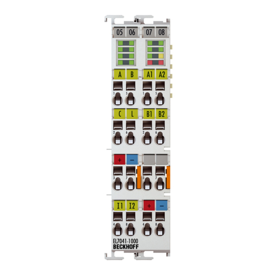
Page 20: Fig. 12 El7041-1000
Product overview Fig. 12: EL7041-1000 Stepper motor terminal, 50 V , 5 A, with incremental encoder The EL7041-x00x EtherCAT Terminal is intended for stepper motors with medium performance range. The PWM output stages cover a wide range of voltages and currents. Together with two inputs for limit switches, they are located in the EtherCAT Terminal. - Page 21 Product overview Application example • Chapter "Commissioning", ◦ Application example [} 166] EL70x1 Version: 4.4...
-
Page 22: El7041-X00X - Technical Data
Product overview EL7041-x00x - Technical data Technical data EL7041-0000 EL7041-0001 EL7041-1000 Number of outputs 1 stepper motor, 2 phases Number of digital inputs 2 limit position, 4 for an en- 1 limit position, 4 for an en- 2 limit position, 4 for an en- coder system coder system coder system... -
Page 23: Technology
The EL7031 and EL7041 Stepper Motor terminals differ in terms of performance. EL7031 With a size of only 12 mm, the EL7031 [} 16] covers the lower performance range. The supply voltage can be up to 24 V . The device is designed for simple integration into the 24 V control voltage system. - Page 24 EtherCAT Terminal. The EL7031 and EL7041 apply a controlled current to the motor winding. If the supply voltage falls below the nominal voltage, the power output stage can no longer apply the full current, resulting in a loss of torque. It is desirable to aim for systems with small winding resistance and high supply voltage in order to limit warming and achieve high torque at high speeds.
- Page 25 (transmission). An elegant solution for improving positioning accuracy is the microstepping function offered by the EL7031 and EL7041. It enables up to 64 intermediate steps. The smaller "artificial" step angle has a further positive effect: The drive can be operated at higher speed, yet with the same precision. The maximum speed is unchanged, despite the fact that the drive operates at the limit of mechanical resolution.
- Page 26 Product overview 8. Different measures are available for optimizing the performance of the drive: using lighter materials or hollow instead of solid body, reducing mechanical mass. The control system can also have significant influence on the behavior of the drive. The Bus Terminal enables operation with different supply volt- ages.
-
Page 27: Basics Communication
Due to automatic cable detection (auto-crossing) symmetric (1:1) or cross-over cables can be used between EtherCAT devices from Beckhoff. Recommended cables Suitable cables for the connection of EtherCAT devices can be found on the Beckhoff web- site! Note E-Bus supply A bus coupler can supply the EL terminals added to it with the E-bus system voltage of 5 V;... -
Page 28: General Notes For Setting The Watchdog
Basics communication Fig. 13: System manager current calculation Malfunction possible! The same ground potential must be used for the E-Bus supply of all EtherCAT terminals in a terminal block! Attention General notes for setting the watchdog ELxxxx terminals are equipped with a safety feature (watchdog) that switches off the outputs after a specifiable time e.g. -
Page 29: Fig. 14 Ethercat Tab -> Advanced Settings -> Behavior -> Watchdog
Basics communication Fig. 14: EtherCAT tab -> Advanced Settings -> Behavior -> Watchdog Notes: • the multiplier is valid for both watchdogs. • each watchdog has its own timer setting, the outcome of this in summary with the multiplier is a resulting time. -
Page 30: Ethercat State Machine
Basics communication Example "Set SM watchdog" This checkbox enables manual setting of the watchdog times. If the outputs are set and the EtherCAT communication is interrupted, the SM watchdog is triggered after the set time and the outputs are erased. This setting can be used for adapting a terminal to a slower EtherCAT master or long cycle times. -
Page 31: Fig. 15 States Of The Ethercat State Machine
Basics communication Fig. 15: States of the EtherCAT State Machine Init After switch-on the EtherCAT slave in the Init state. No mailbox or process data communication is possible. The EtherCAT master initializes sync manager channels 0 and 1 for mailbox communication. Pre-Operational (Pre-Op) During the transition between Init and Pre-Op the EtherCAT slave checks whether the mailbox was initialized correctly. -
Page 32: Coe Interface
Basics communication Boot In the Boot state the slave firmware can be updated. The Boot state can only be reached via the Init state. In the Boot state mailbox communication via the file access over EtherCAT (FoE) protocol is possible, but no other mailbox communication and no process data communication. -
Page 33: Fig. 16 "Coe Online " Tab
Basics communication Fig. 16: "CoE Online " tab The figure above shows the CoE objects available in device "EL2502", ranging from 0x1000 to 0x1600. The subindices for 0x1018 are expanded. Data management and function "NoCoeStorage" Some parameters, particularly the setting parameters of the slave, are configurable and writeable. This can be done in write or read mode •... -
Page 34: Fig. 17 Startup List In The Twincat System Manager
Startup list Changes in the local CoE list of the terminal are lost if the terminal is replaced. If a terminal is replaced with a new Beckhoff terminal, it will have the default settings. It is therefore ad- Note visable to link all changes in the CoE list of an EtherCAT slave with the Startup list of the slave, which is processed whenever the EtherCAT fieldbus is started. -
Page 35: Fig. 18 Offline List
Basics communication Online/offline list While working with the TwinCAT System Manager, a distinction has to be made whether the EtherCAT device is "available", i.e. switched on and linked via EtherCAT and therefore online, or whether a configuration is created offline without connected slaves. In both cases a CoE list as shown in Fig. -
Page 36: Fig. 19 Online List
• Channel 1: parameter range 0x8010:00 ... 0x801F:255 • Channel 2: parameter range 0x8020:00 ... 0x802F:255 • ... This is generally written as 0x80n0. Detailed information on the CoE interface can be found in the EtherCAT system documentation on the Beckhoff website. Version: 4.4 EL70x1... -
Page 37: Distributed Clock
Basics communication Distributed Clock The distributed clock represents a local clock in the EtherCAT slave controller (ESC) with the following characteristics: • Unit 1 ns • Zero point 1.1.2000 00:00 • Size 64 bit (sufficient for the next 584 years; however, some EtherCAT slaves only offer 32-bit support, i.e. -
Page 38: Mounting And Wiring
Mounting and wiring Mounting and wiring Installation on mounting rails Risk of electric shock and damage of device! Bring the bus terminal system into a safe, powered down state before starting installation, disassembly or wiring of the Bus Terminals! WARNING Assembly Fig. 20: Attaching on mounting rail The Bus Coupler and Bus Terminals are attached to commercially available 35 mm mounting rails (DIN rails... -
Page 39: Fig. 21 Disassembling Of Terminal
Mounting and wiring Disassembly Fig. 21: Disassembling of terminal Each terminal is secured by a lock on the mounting rail, which must be released for disassembly: 1. Pull the terminal by its orange-colored lugs approximately 1 cm away from the mounting rail. In doing so for this terminal the mounting rail lock is released automatically and you can pull the terminal out of the bus terminal block easily without excessive force. -
Page 40: Installation Instructions For Enhanced Mechanical Load Capacity
Mounting and wiring Fig. 22: Power contact on left side Possible damage of the device Note that, for reasons of electromagnetic compatibility, the PE contacts are capacitatively coupled to the mounting rail. This may lead to incorrect results during insulation testing or Attention to damage on the terminal (e.g. -
Page 41: Connection
Mounting and wiring Additional installation instructions For terminals with enhanced mechanical load capacity, the following additional installation instructions apply: • The enhanced mechanical load capacity is valid for all permissible installation positions • Use a mounting rail according to EN 60715 TH35-15 •... -
Page 42: Fig. 24 Pluggable Wiring
Mounting and wiring Pluggable wiring (ESxxxx / KSxxxx) Fig. 24: Pluggable wiring The terminals of ESxxxx and KSxxxx series feature a pluggable connection level. The assembly and wiring procedure for the KS series is the same as for the ELxxxx and KLxxxx series. The KS/ES series terminals enable the complete wiring to be removed as a plug connector from the top of the housing for servicing. -
Page 43: Wiring
Mounting and wiring 4.3.2 Wiring Risk of electric shock and damage of device! Bring the bus terminal system into a safe, powered down state before starting installation, disassembly or wiring of the Bus Terminals! WARNING Terminals for standard wiring ELxxxx/KLxxxx and for pluggable wiring ESxxxx/KSxxxx Fig. 26: Connecting a cable on a terminal point Up to eight terminal points enable the connection of solid or finely stranded cables to the Bus Terminal. -
Page 44: Shielding
Mounting and wiring Terminal housing High Density Housing Wire size width (single core wires) 0.08 ... 1.5 mm Wire size width (fine-wire conductors) 0.25 ... 1.5 mm Wire size width (conductors with a wire end sleeve) 0.14 ... 0.75 mm Wire size width (ultrasonically “bonded" conductors) only 1.5 mm Wire stripping length 8 ... -
Page 45: Installation Position For Operation With Or Without Fan
Mounting and wiring Fig. 28: Incorrect configuration Installation position for operation with or without fan Constraints regarding installation position and operating temperature range When installing the terminals ensure that an adequate spacing is maintained between other components above and below the terminal in order to guarantee adequate ventilation! Attention Prescribed installation position for operation without fan The prescribed installation position requires the mounting rail to be installed horizontally and the connection... -
Page 46: Fig. 29 Recommended Distances Of Installation Position For Operating Without Fan
Mounting and wiring Fig. 29: Recommended distances of installation position for operating without fan Compliance with the distances shown in Fig. “Recommended distances of installation position for operating without fan” is recommended. For further information regarding the operation without fan refer to the Technical Data of the terminal. Standard installation position for operation with fan The standard installation position for operation with fan requires the mounting rail to be installed horizontally and the connection surfaces of the EL/KL terminals to face forward (see Fig. -
Page 47: Fig. 30 Recommended Distances For Installation Position For Operation With Fan
Mounting and wiring Fig. 30: Recommended distances for installation position for operation with fan Other installation positions Due to the enforced effect of the fan on the ventilation of the terminals, other installation positions (see Fig. “Other installation positions, example 1 + 2“) may be permitted where appropriate. See corresponding notes in the Technical Data of the terminal. -
Page 48: Fig. 32 Other Installation Positions, Example 2
Mounting and wiring Fig. 32: Other installation positions, example 2 Version: 4.4 EL70x1... -
Page 49: Ul Notice - Compact Motion
Beckhoff EtherCAT modules are intended for use with Beckhoff’s UL Listed EtherCAT Sys- tem only. Examination For cULus examination, the Beckhoff I/O System has only been investigated for risk of fire and electrical shock (in accordance with UL508 and CSA C22.2 No. 142). For devices with Ethernet connectors Not for connection to telecommunication circuits. - Page 50 Mounting and wiring • from a voltage supply complying with NEC class 2. A voltage source complying with NEC class 2 may not be connected in series or parallel with another NEC class 2 compliant voltage supply! These requirements apply to the supply of all EtherCAT bus couplers, power adaptor terminals, Bus Terminals and their power contacts.
-
Page 51: Leds And Connection
Motor turns counter-clockwise Enable green Motor control is blocked (index 0x6010:02 is not set) or EL7031 is not ready for operation Motor control is activated (index 0x6010:02 is set) or EL7031 is ready for operation Warning yellow off no defect Configuration error, e.g.:... -
Page 52: General Connection Examples
Connecting a motor strand to the terminal points of different output drivers (e.g. to A1 and B1) can lead to destruction of the output drivers of stepper motor terminal! Connection types The EL7031 Stepper Motor terminal has bipolar output stages and can control bipolar and unipolar motors. Version: 4.4 EL70x1... -
Page 53: Fig. 35 Bipolar Motors
These two examples show the connection of the bipolar Beckhoff motors AS1010, AS1020 or AS1030. Note Further information on stepper motors from Beckhoff can be found in the associated docu- mentation available for download from our website at http://www.beckhoff.de/. Unipolar motors Fig. 36: Bipolar control of a unipolar motor,... -
Page 54: Leds And Connection
Mounting and wiring EL7041 4.8.1 LEDs and connection 4.8.1.1 EL7041-0000 Risk of injury through electric shock and damage to the device! Bring the Bus Terminals system into a safe, de-energized state before starting mounting, disassembly or wiring of the Bus Terminals. WARNING Fig. 37: EL7041-0000 LEDs LEDs (left prism) - Page 55 Mounting and wiring LEDs (right prism) Color Meaning Driver green on Driver stage ready for operation Power green off Supply voltage (50 V ) not available or motor control is blocked (index 0x6010:02 [} 201] is not set) Supply voltage (50 V ) present Turn CW green on Motor turns clockwise Turn...
-
Page 56: Fig. 38 El7041-0000 Connection
Mounting and wiring Connection Fig. 38: EL7041-0000 Connection Connection (left-hand section of the housing) Terminal Name Signal point Encoder input A Encoder input C (zero input) The current counter value is saved as a reference mark in the latch register if the bit in object 0x7000:01 [} 202] is set and a rising edge occurs at encoder input C. - Page 57 Mounting and wiring Connection (right-hand section of the housing) Terminal Name Signal point Motor winding A Motor winding B Motor supply Supply for output stages (maximum +50 V +50 V Motor supply Supply for output stages (maximum +50 V +50 V Motor winding A Motor winding B Motor supply Supply for output stages (0 V...
-
Page 58: Fig. 39 El7041-0001 Leds
Mounting and wiring 4.8.1.2 EL7041-0001 Risk of injury through electric shock and damage to the device! Bring the Bus Terminals system into a safe, de-energized state before starting mounting, disassembly or wiring of the Bus Terminals. WARNING Fig. 39: EL7041-0001 LEDs LEDs (left prism) Color Meaning... - Page 59 Mounting and wiring LEDs (right prism) Color Meaning Driver green Driver stage ready for operation Power green Supply voltage (50 V ) not available or motor control is blocked (index 0x6010:02 [} 201] is not set) Supply voltage (50 V ) present Turn CW green Motor turns clockwise Turn green...
-
Page 60: Fig. 40 El7041-0001 Connection
Mounting and wiring Connection Fig. 40: EL7041-0001 Connection Connection (left-hand section of the housing) Terminal Name Signal point Encoder input A Encoder input C (zero input) The current counter value is saved as a reference mark in the latch register if the bit in object 0x7000:01 [} 202] is set and a rising edge occurs at encoder input C. - Page 61 Mounting and wiring Connection (right-hand section of the housing) Terminal Name Signal point Motor winding A Motor winding B Motor supply Supply for output stages (maximum +50 V +50 V Motor supply Supply for output stages (maximum +50 V +50 V Motor winding A Motor winding B Motor supply Supply for output stages (0 V...
-
Page 62: Fig. 41 El7041-1000 Leds
Mounting and wiring 4.8.1.3 EL7041-1000 Risk of injury through electric shock and damage to the device! Bring the Bus Terminals system into a safe, de-energized state before starting mounting, disassembly or wiring of the Bus Terminals. WARNING Fig. 41: EL7041-1000 LEDs LEDs (left prism) Color Meaning... - Page 63 Mounting and wiring LEDs (right prism) Color Meaning Driver green Driver stage ready for operation Power green Supply voltage (50 V ) not available or motor control is blocked (index 0x6010:02 [} 219] is not set) Supply voltage (50 V ) present Turn CW green Motor turns clockwise Turn green...
- Page 64 Mounting and wiring Connection Fig. 42: EL7041-1000 Connection Connection (left-hand section of the housing) Terminal Name Signal point Encoder input A Encoder input C (zero input) The current counter value is saved as a reference mark in the latch register if the bit in object 0x7000:01 is set and a rising edge occurs at encoder input C.
- Page 65 Mounting and wiring Connection (right-hand section of the housing) Terminal point Name Signal Motor winding A Motor winding B Sense A reserved, no connection permitted Motor supply Supply for output stages (maximum +50 V +50 V Motor winding A Motor winding B Sense B reserved, no connection permitted Motor supply...
-
Page 66: General Connection Examples
Bipolar motors Fig. 43: Bipolar motors Documentation for stepper motors from Beckhoff These two examples show the connection of the bipolar Beckhoff motors AS1010, AS1020, AS1030, AS1050 or AS1060. Further information on stepper motors from Beckhoff can be Note found in the associated documentation available for download from our website at http:// www.beckhoff.de/. - Page 67 Mounting and wiring Unipolar motors Bipolar control of a unipolar motor Fig. 44: Bipolar control of a unipolar motor Only one half of each winding is controlled. Encoder Connecting an encoder (24 V) Fig. 45: Connecting an encoder (24 V) The encoder is supplied from the power contacts via terminal points 3 (+24 V) and 7 (0 V). EL70x1 Version: 4.4...
-
Page 68: Commissioning
• "offline": The configuration can be customized by adding and positioning individual components. These can be selected from a directory and configured. ◦ The procedure for offline mode can be found under http://infosys.beckhoff.com: TwinCAT 2 → TwinCAT System Manager → IO - Configuration → Adding an I/O Device •... - Page 69 Commissioning Fig. 46: Relationship between user side (commissioning) and installation The user inserting of certain components (I/O device, terminal, box...) is the same in TwinCAT 2 and TwinCAT 3. The descriptions below relate to the online procedure. Sample configuration (actual configuration) Based on the following sample configuration, the subsequent subsections describe the procedure for TwinCAT 2 and TwinCAT 3: •...
- Page 70 Commissioning Fig. 47: Control configuration with Embedded PC, input (EL1004) and output (EL2008) Note that all combinations of a configuration are possible; for example, the EL1004 terminal could also be connected after the coupler, or the EL2008 terminal could additionally be connected to the CX2040 on the right, in which case the EK1100 coupler wouldn’t be necessary.
- Page 71 Commissioning Generally, TwinCAT can be used in local or remote mode. Once the TwinCAT system including the user interface (standard) is installed on the respective PLC, TwinCAT can be used in local mode and thereby the next step is "Insert Device [} 72]". If the intention is to address the TwinCAT runtime environment installed on a PLC as development environment remotely from another system, the target system must be made known first.
- Page 72 Commissioning After confirmation with "OK" the target system can be accessed via the System Manager. Adding devices In the configuration tree of the TwinCAT 2 System Manager user interface on the left, select "I/O Devices” and then right-click to open a context menu and select "Scan Devices…", or start the action in the menu bar .
- Page 73 Commissioning Fig. 53: Mapping of the configuration in the TwinCAT 2 System Manager The whole process consists of two stages, which may be performed separately (first determine the devices, then determine the connected elements such as boxes, terminals, etc.). A scan can also be initiated by selecting "Device ..."...
- Page 74 Commissioning • Graphical languages ◦ Function Block Diagram (FBD) ◦ Ladder Diagram (LD) ◦ The Continuous Function Chart Editor (CFC) ◦ Sequential Function Chart (SFC) The following section refers to Structured Text (ST). After starting TwinCAT PLC Control, the following user interface is shown for an initial project: Fig. 55: TwinCAT PLC Control after startup Sample variables and a sample program have been created and stored under the name "PLC_example.pro": Version: 4.4...
- Page 75 Commissioning Fig. 56: Sample program with variables after a compile process (without variable integration) Warning 1990 (missing "VAR_CONFIG") after a compile process indicates that the variables defined as external (with the ID "AT%I*" or "AT%Q*") have not been assigned. After successful compilation, TwinCAT PLC Control creates a "*.tpy"...
- Page 76 Commissioning Select the PLC configuration "PLC_example.tpy" in the browser window that opens. The project including the two variables identified with "AT" are then integrated in the configuration tree of the System Manager: Fig. 58: PLC project integrated in the PLC configuration of the System Manager The two variables "bEL1004_Ch4"...
- Page 77 Commissioning Fig. 60: Selecting PDO of type BOOL According to the default setting, certain PDO objects are now available for selection. In this sample the input of channel 4 of the EL1004 terminal is selected for linking. In contrast, the checkbox "All types" must be ticked for creating the link for the output variables, in order to allocate a set of eight separate output bits to a byte variable.
- Page 78 Commissioning Fig. 62: Application of a "Goto Link" variable, using "MAIN.bEL1004_Ch4" as a sample The process of assigning variables to the PDO is completed via the menu selection "Actions" → "Generate Mappings”, key Ctrl+M or by clicking on the symbol in the menu. This can be visualized in the configuration: The process of creating links can also take place in the opposite direction, i.e.
- Page 79 Commissioning Fig. 63: Choose target system (remote) In this sample "Runtime system 1 (port 801)" is selected and confirmed. Link the PLC with the real-time system via menu option "Online" → "Login", the F11 key or by clicking on the symbol . The control program can then be loaded for execution.
- Page 80 Commissioning Fig. 64: PLC Control logged in, ready for program startup The PLC can now be started via "Online" → "Run", F5 key or 5.1.2 TwinCAT 3 Startup TwinCAT makes the development environment areas available together with Microsoft Visual Studio: after startup, the project folder explorer appears on the left in the general window area (cf.
- Page 81 Commissioning Fig. 65: Initial TwinCAT 3 user interface First create a new project via (or under "File"→“New"→ "Project…"). In the following dialog make the corresponding entries as required (as shown in the diagram): Fig. 66: Create new TwinCAT project The new project is then available in the project folder explorer: EL70x1 Version: 4.4...
- Page 82 Commissioning Fig. 67: New TwinCAT3 project in the project folder explorer Generally, TwinCAT can be used in local or remote mode. Once the TwinCAT system including the user interface (standard) is installed on the respective PLC, TwinCAT can be used in local mode and thereby the next step is "Insert Device [} 83]".
- Page 83 Commissioning Use "Search (Ethernet)..." to enter the target system. Thus a next dialog opens to either: • enter the known computer name after "Enter Host Name / IP:" (as shown in red) • perform a "Broadcast Search" (if the exact computer name is not known) •...
- Page 84 Commissioning Fig. 71: Automatic detection of I/O devices: selection the devices to be integrated Confirm the message "Find new boxes", in order to determine the terminals connected to the devices. "Free Run" enables manipulation of input and output values in "Config mode" and should also be acknowledged. Based on the sample configuration [} 69] described at the beginning of this section, the result is as follows: Fig. 72: Mapping of the configuration in VS shell of the TwinCAT3 environment The whole process consists of two stages, which may be performed separately (first determine the devices,...
- Page 85 Commissioning Fig. 73: Reading of individual terminals connected to a device This functionality is useful if the actual configuration is modified at short notice. Programming the PLC TwinCAT PLC Control is the development environment for the creation of the controller in different program environments: TwinCAT PLC Control supports all languages described in IEC 61131-3.
- Page 86 Commissioning Fig. 74: Adding the programming environment in "PLC" In the dialog that opens select "Standard PLC project" and enter "PLC_example" as project name, for example, and select a corresponding directory: Fig. 75: Specifying the name and directory for the PLC programming environment The "Main"...
- Page 87 Commissioning Fig. 76: Initial "Main" program of the standard PLC project To continue, sample variables and a sample program have now been created: EL70x1 Version: 4.4...
- Page 88 Commissioning Fig. 77: Sample program with variables after a compile process (without variable integration) The control program is now created as a project folder, followed by the compile process: Fig. 78: Start program compilation The following variables, identified in the ST/ PLC program with "AT%", are then available in under "Assignments"...
- Page 89 Commissioning Fig. 79: Creating the links between PLC variables and process objects In the window that opens, the process object for the variable "bEL1004_Ch4" of type BOOL can be selected from the PLC configuration tree: Fig. 80: Selecting PDO of type BOOL According to the default setting, certain PDO objects are now available for selection.
- Page 90 Commissioning Fig. 81: Selecting several PDOs simultaneously: activate "Continuous" and "All types" Note that the "Continuous" checkbox was also activated. This is designed to allocate the bits contained in the byte of the variable "nEL2008_value" sequentially to all eight selected output bits of the EL2008 terminal. In this way it is possible to subsequently address all eight outputs of the terminal in the program with a byte corresponding to bit 0 for channel 1 to bit 7 for channel 8 of the PLC.
- Page 91 Commissioning Activation of the configuration The allocation of PDO to PLC variables has now established the connection from the controller to the inputs and outputs of the terminals. The configuration can now be activated with or via the menu under "TwinCAT"...
-
Page 92: Twincat 2
5.2.1 Installation of the TwinCAT real-time driver In order to assign real-time capability to a standard Ethernet port of an IPC controller, the Beckhoff real-time driver has to be installed on this port under Windows. This can be done in several ways. One option is described here. - Page 93 Commissioning Fig. 84: System Manager “Options” (TwinCAT 2) This have to be called up by the Menü “TwinCAT” within the TwinCAT 3 environment: Fig. 85: Call up under VS Shell (TwinCAT 3) The following dialog appears: Fig. 86: Overview of network interfaces Interfaces listed under “Compatible devices” can be assigned a driver via the “Install” button. A driver should only be installed on compatible devices.
- Page 94 Commissioning Fig. 87: EtherCAT device properties(TwinCAT 2): click on „Compatible Devices…“ of tab “Adapter” TwinCAT 3: the properties of the EtherCAT device can be opened by double click on “Device .. (EtherCAT)” within the Solution Explorer under “I/O”: After the installation the driver appears activated in the Windows overview for the network interface (Windows Start →...
- Page 95 Commissioning Fig. 89: Exemplary correct driver setting for the Ethernet port Other possible settings have to be avoided: EL70x1 Version: 4.4...
- Page 96 Commissioning Fig. 90: Incorrect driver settings for the Ethernet port Version: 4.4 EL70x1...
- Page 97 Commissioning IP address of the port used IP address/DHCP In most cases an Ethernet port that is configured as an EtherCAT device will not transport general IP packets. For this reason and in cases where an EL6601 or similar devices are Note used it is useful to specify a fixed IP address for this port via the “Internet Protocol TCP/IP”...
-
Page 98: Notes Regarding Esi Device Description
The files are read (once) when a new System Manager window is opened, if they have changed since the last time the System Manager window was opened. A TwinCAT installation includes the set of Beckhoff ESI files that was current at the time when the TwinCAT build was created. - Page 99 1018 in the configuration. This is also stated by the Beckhoff compatibility rule. Refer in particular to the chapter ‘General notes on the use of Beckhoff EtherCAT IO components’ and for manual configuration to the chapter ‘Offline configuration creation’ [} 103].
- Page 100 Commissioning Fig. 95: File OnlineDescription.xml created by the System Manager Is a slave desired to be added manually to the configuration at a later stage, online created slaves are indicated by a prepended symbol “>” in the selection list (see Figure “Indication of an online recorded ESI of EL2521 as an example”).
- Page 101 Commissioning Reasons may include: • Structure of the *.xml does not correspond to the associated *.xsd file → check your schematics • Contents cannot be translated into a device description → contact the file manufacturer EL70x1 Version: 4.4...
-
Page 102: Twincat Esi Updater
Commissioning 5.2.3 TwinCAT ESI Updater For TwinCAT 2.11 and higher, the System Manager can search for current Beckhoff ESI files automatically, if an online connection is available: Fig. 98: Using the ESI Updater (>= TwinCAT 2.11) The call up takes place under: “Options” → "Update EtherCAT Device Descriptions"... -
Page 103: Offline Configuration Creation
Commissioning • the devices/modules be connected to the power supply and ready for communication • TwinCAT must be in CONFIG mode on the target system. The online scan process consists of: • detecting the EtherCAT device [} 108] (Ethernet port at the IPC) •... - Page 104 Commissioning This query may appear automatically when the EtherCAT device is created, or the assignment can be set/ modified later in the properties dialog; see Fig. “EtherCAT device properties (TwinCAT 2)”. Fig. 103: EtherCAT device properties (TwinCAT 2) TwinCAT 3: the properties of the EtherCAT device can be opened by double click on “Device .. (EtherCAT)” within the Solution Explorer under “I/O”: Selecting the Ethernet port Ethernet ports can only be selected for EtherCAT devices for which the TwinCAT real-time...
- Page 105 (i.e. highest) revision and therefore the latest state of production is displayed in the selection dialog for Beckhoff devices. To show all device revisions available in the system as ESI descriptions tick the “Show Hidden Devices” check box, see Fig. “Display of previous revisions”.
- Page 106 If current ESI descriptions are available in the TwinCAT system, the last revision offered in the selection dialog matches the Beckhoff state of production. It is recommended to use the last device revision when creating a new configuration, if current Beckhoff devices are used in the real application. Older revisions should only be used if older devices from stock are to be used in the application.
- Page 107 Commissioning Fig. 109: EtherCAT terminal in the TwinCAT tree (left: TwinCAT 2; right: TwinCAT 3) EL70x1 Version: 4.4...
-
Page 108: Online Configuration Creation
Commissioning 5.2.6 ONLINE configuration creation Detecting/scanning of the EtherCAT device The online device search can be used if the TwinCAT system is in CONFIG mode. This can be indicated by a symbol right below in the information bar: • on TwinCAT 2 by a blue display “Config Mode” within the System Manager window: •... - Page 109 [} 113] with the defined initial configura- tion.Background: since Beckhoff occasionally increases the revision version of the deliv- ered products for product maintenance reasons, a configuration can be created by such a scan which (with an identical machine construction) is identical according to the device list;...
- Page 110 Likewise, A might create spare parts stores worldwide for the coming series-produced machines with EL2521-0025-1018 terminals. After some time Beckhoff extends the EL2521-0025 by a new feature C. Therefore the FW is changed, outwardly recognizable by a higher FW version and a new revision -1019. Nevertheless the new device naturally supports functions and interfaces of the predecessor version(s);...
- Page 111 Commissioning Fig. 117: Scan query after automatic creation of an EtherCAT device (left: TwinCAT 2; right: TwinCAT 3) Fig. 118: Manual triggering of a device scan on a specified EtherCAT device (left: TwinCAT 2; right: TwinCAT 3) In the System Manager (TwinCAT 2) or the User Interface (TwinCAT 3) the scan process can be monitored via the progress bar at the bottom in the status bar.
- Page 112 Commissioning Fig. 123: Online display example Please note: • all slaves should be in OP state • the EtherCAT master should be in “Actual State” OP • “frames/sec” should match the cycle time taking into account the sent number of frames •...
- Page 113 A ‘ChangeTo’ or ‘Copy’ should only be Attention carried out with care, taking into consideration the Beckhoff IO compatibility rule (see above). The device configuration is then replaced by the revision found; this can affect the supported process data and functions.
- Page 114 If current ESI descriptions are available in the TwinCAT system, the last revision offered in the selection dialog matches the Beckhoff state of production. It is recommended to use the last device revision when creating a new configuration, if current Beckhoff devices are used in the real application. Older revisions should only be used if older devices from stock are to be used in the application.
- Page 115 Commissioning Fig. 128: Correction dialog with modifications Once all modifications have been saved or accepted, click “OK” to transfer them to the real *.tsm configuration. Change to Compatible Type TwinCAT offers a function “Change to Compatible Type…” for the exchange of a device whilst retaining the links in the task.
-
Page 116: Ethercat Subscriber Configuration
Commissioning If called, the System Manager searches in the procured device ESI (in this example: EL1202-0000) for details of compatible devices contained there. The configuration is changed and the ESI-EEPROM is overwritten at the same time – therefore this process is possible only in the online state (ConfigMode). 5.2.7 EtherCAT subscriber configuration In the left-hand window of the TwinCAT 2 System Manager or the Solution Explorer of the TwinCAT 3... - Page 117 Commissioning „EtherCAT“ tab Fig. 133: „EtherCAT“ tab Type EtherCAT device type Product/Revision Product and revision number of the EtherCAT device Auto Inc Addr. Auto increment address of the EtherCAT device. The auto increment address can be used for addressing each EtherCAT device in the communication ring through its physical position.
- Page 118 For Beckhoff EtherCAT EL, ES, EM, EJ and EP slaves the following applies in general: • The input/output process data supported by the device are defined by the manufacturer in the ESI/XML description.
- Page 119 Commissioning Fig. 135: Configuring the process data Manual modification of the process data According to the ESI description, a PDO can be identified as “fixed” with the flag “F” in the PDO overview (Fig. “Configuring the process data”, J). The configuration of such PDOs Note cannot be changed, even if TwinCAT offers the associated dialog (“Edit”).
- Page 120 Commissioning Fig. 136: „Startup“ tab Column Description Transition Transition to which the request is sent. This can either be • the transition from pre-operational to safe-operational (PS), or • the transition from safe-operational to operational (SO). If the transition is enclosed in "<>" (e.g. <PS>), the mailbox request is fixed and cannot be modified or deleted by the user.
- Page 121 Commissioning Fig. 137: “CoE – Online” tab Object list display Column Description Index Index and sub-index of the object Name Name of the object Flags The object can be read, and data can be written to the object (read/write) The object can be read, but no data can be written to the object (read only) An additional P identifies the object as a process data object.
- Page 122 Commissioning Update List The Update list button updates all objects in the displayed list Auto Update If this check box is selected, the content of the objects is updated automatically. Advanced The Advanced button opens the Advanced Settings dialog. Here you can specify which objects are displayed in the list.
- Page 123 Commissioning „Online“ tab Fig. 139: „Online“ tab State Machine Init This button attempts to set the EtherCAT device to the Init state. Pre-Op This button attempts to set the EtherCAT device to the pre-operational state. This button attempts to set the EtherCAT device to the operational state.
- Page 124 • DC-Synchron Advanced Settings… Advanced settings for readjustment of the real time determinant TwinCAT- clock Detailed information to Distributed Clocks are specified on http://infosys.beckhoff.com: Fieldbus Components → EtherCAT Terminals → EtherCAT System documentation → EtherCAT basics → Distributed Clocks 5.2.7.1...
- Page 125 Commissioning Fig. 141: Download revision in Start-up list 5.2.7.2 Detailed description of Process Data tab Sync Manager Lists the configuration of the Sync Manager (SM). If the EtherCAT device has a mailbox, SM0 is used for the mailbox output (MbxOut) and SM1 for the mailbox input (MbxIn).
-
Page 126: General Notes - Ethercat Slave Application
Commissioning Column Description Index PDO index. Size Size of the PDO in bytes. Name Name of the PDO. If this PDO is assigned to a Sync Manager, it appears as a variable of the slave with this parameter as the name. Flags Fixed content: The content of this PDO is fixed and cannot be changed by the System Manager. - Page 127 Fig. “Basic EtherCAT Slave Diagnosis in the PLC” shows an example of an implementation of basic EtherCAT Slave Diagnosis. A Beckhoff EL3102 (2-channel analogue input terminal) is used here, as it offers both the communication diagnosis typical of a slave and the functional diagnosis that is specific to a channel.
- Page 128 Commissioning Fig. 143: Basic EtherCAT Slave Diagnosis in the PLC The following aspects are covered here: Version: 4.4 EL70x1...
- Page 129 Commissioning Code Function Implementation Application/evaluation The EtherCAT Master's diagnostic infor- At least the DevState is to be evaluated for mation the most recent cycle in the PLC. updated acyclically (yellow) or provided The EtherCAT Master's diagnostic informa- acyclically (green). tion offers many more possibilities than are treated in the EtherCAT System Documenta- tion.
- Page 130 Commissioning Fig. 144: EL3102, CoE directory EtherCAT System Documentation The comprehensive description in the EtherCAT System Documentation (EtherCAT Basics --> CoE Interface) must be observed! Note A few brief extracts: • Whether changes in the online directory are saved locally in the slave depends on the device. EL terminals (except the EL66xx) are able to save in this way.
- Page 131 Commissioning Fig. 145: Example of commissioning aid for a EL3204 This commissioning process simultaneously manages • CoE Parameter Directory • DC/FreeRun mode • the available process data records (PDO) Although the "Process Data", "DC", "Startup" and "CoE-Online" that used to be necessary for this are still displayed, it is recommended that, if the commissioning aid is used, the automatically generated settings are not changed by it.
- Page 132 Commissioning Standard setting The advanced settings of the EtherCAT Master are set as standard: • EtherCAT Master: OP • Slaves: OP This setting applies equally to all Slaves. Fig. 146: Default behaviour of the System Manager In addition, the target state of any particular Slave can be set in the "Advanced Settings" dialogue; the standard setting is again OP.
- Page 133 Commissioning Manual Control There are particular reasons why it may be appropriate to control the states from the application/task/PLC. For instance: • for diagnostic reasons • to induce a controlled restart of axes • because a change in the times involved in starting is desirable In that case it is appropriate in the PLC application to use the PLC function blocks from the TcEtherCAT.lib, which is available as standard, and to work through the states in a controlled manner using, for instance, FB_EcSetMasterState.
- Page 134 Commissioning Fig. 149: Illegally exceeding the E-Bus current From TwinCAT 2.11 and above, a warning message "E-Bus Power of Terminal..." is output in the logger window when such a configuration is activated: Fig. 150: Warning message for exceeding E-Bus current Caution! Malfunction possible! The same ground potential must be used for the E-Bus supply of all EtherCAT terminals in a terminal block! Attention...
-
Page 135: Integration Into The Nc Configuration
EtherCAT XML Device Description The display matches that of the CoE objects from the EtherCAT XML Device Description. We recommend downloading the latest XML file from the download area of the Beckhoff Note website and installing it according to installation instructions. - Page 136 Commissioning Fig. 153: Selecting and confirming the axis type • Left-click your axis to select it. Under the Settings tab select "Link To..." (see Fig. Linking the axis with the terminal). Fig. 154: Linking the axis with the terminal • Select the right terminal (Stepper Drive (MDP 703)) and confirm with OK. Fig. 155: Selecting the right terminal •...
- Page 137 Commissioning Fig. 156: Automatic linking of all main variables • Several parameters have to be set before the motor can be started up. The values can be found in section "Configuration of the main parameters". Please set these parameters before continuing with the motor commissioning procedure.
- Page 138 Commissioning Fig. 157: Enabling an axis You can now move the axis with the function keys F1, F2 (Backward) or F3, F4 (Forward). Alternatively you can control the axis via the Functions tab. Example • Select as Reversing Sequence as the start mode. •...
-
Page 139: Configuration Of The Main Parameters
Commissioning Fig. 158: Axis control, "Functions" tab The motor now travels to Position 1, remains there for 1 s and then returns to Position 2. This is repeated until you click Stop. Configuration of the main parameters The specified data apply to an AS 1050-0120 stepper motor and are intended as an example. For other motors the values may vary, depending on the application. - Page 140 Commissioning Fig. 159: Adaptation of current and voltage Base frequency selection Microstepping is set to 1/64 and cannot be changed. However, the base frequency can be changed (default: 2000). To this end select the terminal and select the CoE Online tab. Change the base frequency by double- clicking on the index 0x8012:05 [} 197] "Speed range"...
- Page 141 Commissioning Fig. 161: Selecting the feedback system KA factor The K factor can be used to adapt the current during the acceleration phases. The current increase is calculated as follows. Current increase in mA = speed difference x K / 1000 The steeper the speed ramp, the higher the current increase. EL70x1 Version: 4.4...
- Page 142 Commissioning Fig. 162: Speed ramps This value can be set in index 0x8011:07 "Ka factor (curr.)" (see fig. Setting the K -factor). Fig. 163: Setting the KA factor NC settings Reference velocity selection The maximum velocity can be calculated from the base frequency and the motor frequency. = base frequency / motor frequency = (2000 full steps / s) / (200 full steps / rev) = 10 revolutions / The reference velocity can be calculated by multiplying the maximum velocity with the distance per revolution.
- Page 143 Commissioning Fig. 164: Reference velocity parameter Dead time compensation The dead time compensation can be adjusted on the Time Compensation tab of Axis1_ENC. It should theoretically be 3 cycles of the NC cycle time, although in practice 4 cycles are preferable. Therefore, the settings of the parameters Time Compensation Mode Encoder should be ‚ON (with velocity) )‘...
- Page 144 Commissioning Fig. 166: Setting the Scaling Factor Calculation of the scaling factor with encoder, 4-fold evaluation: SF = distance per revolution / (increments x 4) = 360° / (1024 x 4) = 0.087890625 ° / INC without encoder: SF = distance per revolution / (full steps x microsteps) = 360° / (200 x 64) = 0.028125 ° / INC Position lag monitoring The position lag monitoring function checks whether the current position lag of an axis has exceeded the limit value.
- Page 145 Commissioning factors In the NC two proportional factors K can be set under "Axis 1_Ctrl " in tab "Parameter". First select the position controller Type with two P constants (with Ka) under the “NC Controller” tab. The two P constants are for the Standstill range and for the Moving range (see Fig.
-
Page 146: Basic Principles For The Positioning Interface
Commissioning Fig. 170: Dead band for position errors Setting the acceleration time In order to pass through any resonances that may occur as quickly as possible, the ramps for the acceleration time and the deceleration time should be as steep as possible. Fig. 171: Setting the acceleration time on the "Dynamics"... -
Page 147: Predefined Pdo Assignment
Commissioning 5.6.1 Predefined PDO Assignment The "Predefined PDO Assignment" enables a simplified selection of the process data. Select the function "Positioning interface" or "Positioning interface compact" in the lower part of the Process data tab. As a result, all necessary PDOs are automatically activated and the unnecessary PDOs are deactivated. Fig. 172: Predefined PDO Assignment 5.6.2 Parameter set... - Page 148 Commissioning 0.5% is subtracted from the position determined. If the deceleration ramp has ended and the destination has not yet been reached, the terminal drives at the velocity “Velocity min.” to the destination. It must be configured in such a way that the motor is able to stop abruptly and without a step loss at this velocity. Velocity max.: The maximum velocity with which the motor drives during a travel command "Speed range"...
-
Page 149: Information And Diagnostic Data
Commissioning Time information: The meaning of the "Actual drive time" displayed is configured by this parameter. At present this value cannot be changed, since there are no further selection options. The elapsed time of the travel command is displayed. Invert calibration cam search direction: In relation to a positive direction of rotation, the direction of the search for the calibration cam is configured here (travel towards the cam). -
Page 150: States Of The Internal State Machine
Commissioning 5.6.4 States of the internal state machine The state (drive controller) (Index 0x9020:03) provides information about the current state of the internal state machine. For diagnostic purposes this can be read out by the PLC for the propagation delay. The internal cycle works constantly with 250 µs. -
Page 151: Start Types
Commissioning Evaluate status Monitor the terminal state and, if necessary, dynamically change the target position. Error handling In case of error, procure the necessary information from the CoE and evaluate it. Fig. 175: Flow diagram for a travel command 5.6.6 Start types The Positioning interface offers different types of positioning. - Page 152 Commissioning Name Command Group Description ABSOLUTE 0x0001 Absolute positioning to a specified target position Standard [} 152] RELATIVE 0x0002 Relative positioning to a calculated target position; a specified posi- tion difference is added to the current position ENDLESS_PLUS 0x0003 Endless travel in the positive direction of rotation (direct specification of a speed) ENDLESS_MINUS 0x0004...
-
Page 153: Fig. 178 Endless Travel
Commissioning Fig. 177: Relative positioning ENDLESS_PLUS / ENDLESS_MINUS The two start types ENDLESS_PLUS and ENDLESS_MINUS offer the possibility in the Positioning Interface to specify a direct motor velocity in order to travel endlessly in the positive or negative direction with the specified accelerations. -
Page 154: Fig. 180 Calibration With Cam
Commissioning Caution when using the RELATIVE_CHANGE positioning The change by means of RELATIVE_CHANGE must be used with caution, since the cur- rent position of the motor is also used here as the start position. Due to propagation delays Attention in the system, the position indicated in the PDO never corresponds to the actual position of the motor! Therefore a difference to the desired target position always results in the calcu- lation of the transferred position delta. -
Page 155: Modulo - General Description
Commissioning If calibration by hardware is not possible due to the circumstances of the application, the user can also set the Calibrated bit manually or automatically. The manual setting or deletion takes place with the commands SET_CALIBRATION and CLEAR_CALIBRATION. It is simpler, however, if the standard start types (Index 0x8021:01) are set to SET_CALIBRATION_AUTO. The Calibrated bit will now be set automatically by the first rising edge on Enable. -
Page 156: Fig. 182 Effect Of The Modulo Tolerance Window - Modulo Target Position 0° In Positive Direction
Commissioning Fig. 182: Effect of the modulo tolerance window - modulo target position 0° in positive direction Example An axis is positioned to 0°, with the result that subsequently the actual position of the axis is exactly 0°. A further modulo travel command to 360° in positive direction results in a full turn, with the subsequent modulo position of the axis of once again being exactly 0°. - Page 157 Commissioning identically, as long the actual position is between 359° and 1°. If the position exceeds 0° by less than 1°, the axis is re-positioned in positive direction at a modulo start. In both cases, a target position of 0° therefore leads to minimum movement to exactly 0°.
- Page 158 Commissioning The following table shows examples of modulo positioning with whole revolutions Modulo start type Absolute start Modulo tar- Relative Absolute Modulo end Note position get position travel path end posi- position tion MODULO_PLUS 90.00° 90.00° 0.00° 90.00° 90.00° MODULO_PLUS 90.90°...
-
Page 159: Examples Of Two Travel Commands With A Dynamic Change Of The Target Position
Commissioning 5.6.8 Examples of two travel commands with a dynamic change of the target position Without overrun of the target position Time POS Outputs POS Inputs Description Execute = 1 Busy = 1 • Specification of the first parameter Target position = 200000 Accelerate = 1 •... -
Page 160: Fig. 184 Scope Recording With Overrunning Of The Final Target Position
Commissioning With overrun of the target position Time POS Outputs POS Inputs Description Execute = 1 Busy = 1 • Specification of the 1 parameter Target position = 200000 Accelerate = 1 • Start of the 1 acceleration phase Velocity = 5000 Start type = 0x0001 Acceleration = 3000 Deceleration = 5000... -
Page 161: Process Data
Commissioning Process data 5.7.1 Sync Manager (SM) The extent of the process data that is made available can be changed via the “Process data” tab (see Fig. Process data tab SM2, EL70xx (default)). Fig. 185: Process Data tab SM2, EL70xx (default) EL70x1 Version: 4.4... -
Page 162: Pdo Assignment
Commissioning Fig. 186: Process Data tab SM3, EL70xx (default) 5.7.2 PDO Assignment In order to configure the process data, select the desired Sync Manager (SM 2 & 3 can be edited here) in the upper left-hand "Sync Manager" field (see fig. Process data tab SM2, EL70xx (default) and SM3, EL70xx (default)). - Page 163 Commissioning SM2, PDO assignment 0x1C12 Index Index of excluded Size Name PDO content PDOs (byte.bit) 0x1600 0x1601 ENC Control Index 0x7000:01 [} 202] - Enable Latch C (default) compact Index 0x7000:02 [} 202] - Enable Latch extern on positive edge Index 0x7000:03 [} 202] - Set counter Index 0x7000:04 [} 202] - Enable Latch extern on negative edge Index 0x7000:11 [} 202] - Set counter value (16-bit) 0x1601...
- Page 164 Commissioning SM3, PDO Assignment 0x1C13 Index Index of excluded Size Name PDO content PDOs (byte.bit) 0x1A00 0x1A01 ENC Status Index 0x6000:01 [} 201] - Latch C valid (default) compact Index 0x6000:02 [} 201] - Latch extern valid Index 0x6000:03 [} 201] - Set counter done Index 0x6000:04 [} 201] - Counter underflow Index 0x6000:05 [} 201] - Counter overflow Index 0x6000:08 [} 201] - Extrapolation stall...
-
Page 165: Predefined Pdo Assignment
Commissioning SM3, PDO Assignment 0x1C13 Index Index of excluded Size Name PDO content PDOs (byte.bit) 0x1A08 STM External Index 0x6010:15 [} 201] - External position position Table 1: PDO assignment of Sync Managers, EL7041 5.7.3 Predefined PDO Assignment The "Predefined PDO Assignment" enables a simplified selection of the process data. The desired function is selected on the lower part of the "Process Data"... -
Page 166: Application Example
EtherCAT XML Device Description The display matches that of the CoE objects from the EtherCAT XML Device Description. We recommend downloading the latest XML file from the download area of the Beckhoff Note website and installing it according to installation instructions. -
Page 167: Fig. 189 Selecting The Mac Address
Commissioning • Start the System Manager in Config mode. • Please ensure that the I/O configuration matches your actual configuration. In the sample program only one EL7041 is integrated. If further terminals are connected you have to add them or re-scan your configuration. -
Page 168: Fig. 191 Required Libraries
Commissioning Fig. 191: Required libraries Once this is done, certain global variables are declared (see Fig. Global variables). The data types PLCTONC_AXLESTRUCT and NCTOPLC_AXLESTRUCT deal with the communication between the PLC and the NC. Fig. 192: Global variables Once the global variables have been declared, programming can commence. Start with declaring local variables (see Fig. -
Page 169: Fig. 194 Program Code
Commissioning Fig. 194: Program code The motor can then be operated with the aid of the following visualization (see Fig. Visualization). Press Enable to enable the axis. In "Free run mode" you can now use the Left or Right buttons, and the motor will run with a speed defined under fbMoveVelocity_Axis_1 in the selected direction. -
Page 170: Fig. 195 Visualization
Commissioning Fig. 195: Visualization Information on function blocks and data types Further information on the function blocks and data types used can be found in the Beck- hoff Information System. Note Version: 4.4 EL70x1... -
Page 171: El7031 - Object Description And Parameterization
EtherCAT XML Device Description The display matches that of the CoE objects from the EtherCAT XML Device Description. We recommend downloading the latest XML file from the download area of the Beckhoff Note website and installing it according to installation instructions. - Page 172 Commissioning Index 8010 STM Motor Settings Ch.1 Index (hex) Name Meaning Data type Flags Default 8010:0 STM Motor Settings Maximum subindex UINT8 0x11 (17 Ch.1 8010:01 Maximal current Maximum permanent motor coil current (unit: 1 mA) UINT16 0x05DC (1500 8010:02 Reduced current Reduced coil current (reduced torque, unit: 1 mA) UINT16 0x01F4...
- Page 173 Commissioning Index 8012 STM Features Ch.1 Index (hex) Name Meaning Data type Flags Default 8012:0 STM Features Ch.1 Maximum subindex UINT8 0x49 (73 8012:01 Operation mode Operating mode Automatic BIT4 0x00 (0 (currently only direct Direct velocity velocity is sup- Velocity controller ported) Position controller...
- Page 174 Commissioning Index 8012 STM Features Ch.1 Index (hex) Name Meaning Data type Flags Default 8012:19 Select info data 2 Selection "Info data Status word UINT8 0x04 (4 2" Motor voltage coil A (unit 1 mV) Motor voltage coil B (unit 1 mV) Motor current coil A (unit 1 mA) Motor current coil B...
- Page 175 Commissioning Index 8020 POS Settings Ch.1 Index (hex) Name Meaning Data type Flags Default 8020:0 POS Settings Ch.1 Maximum subindex UINT8 0x10(16 8020:01 Velocity min. Minimum set velocity (range: 0-10000) INT16 0x0064 (100 8020:02 Velocity max. Maximum set velocity (range: 0-10000) INT16 0x2710 (10000...
-
Page 176: Command Object
Commissioning Index 8021 POS Features Ch.1 Index Name Meaning Data type Flags Default value 8021:0 POS Features Ch.1 Maximum subindex UINT8 0x16 (22 8021:01 Start type permitted values: UINT16 0x0001 (1 0: Idle 1: Absolute 2: Relative 3: Endless plus 4: Endless minus 6: Additive 24832: Calibration (Hardware sync) -
Page 177: Input Data
Commissioning 5.9.4 Input data Index 6000 ENC Inputs Ch.1 Index (hex) Name Meaning Data type Flags Default 6000:0 ENC Inputs Ch.1 Maximum subindex UINT8 0x16 (22 6000:02 Latch extern valid The counter value was stored via the external latch. BOOLEAN 0x00 (0 6000:03 Set counter done... -
Page 178: Output Data
Commissioning Index 6020 POS Inputs Ch.1 Index (hex) Name Meaning Data type Flags Default 6020:0 POS Inputs Ch.1 Maximum subindex UINT8 0x22 (34 6020:01 Busy A current travel command is active BOOLEAN 0x00 (0 6020:02 In-Target Motor has arrived at target BOOLEAN 0x00 (0 6020:03... - Page 179 Commissioning Index 7020 POS Outputs Ch.1 EL70x1 Version: 4.4...
- Page 180 Commissioning Index (hex) Name Meaning Data type Flags Default 7020:0 POS Outputs Ch.1 Maximum subindex UINT8 0x24 (36 7020:01 Execute Start travel command (rising edge), or prematurely abort BOOLEAN 0x00 (0 travel command (falling edge) 7020:02 Emergency Stop Prematurely abort travel command with an emergency BOOLEAN 0x00 (0 ramp (rising edge)
- Page 181 Commissioning Index (hex) Name Meaning Data type Flags Default 0x6E00 Calibration, Set calibration set manual manually 0x6E01 Calibration, Set calibration au- set manual tomatically auto 0x6F00 Calibration, Clear calibration clear manual manually 7020:23 Acceleration Acceleration specification UINT16 0x0000 (0 7020:24 Deceleration Deceleration specification UINT16...
-
Page 182: Information / Diagnostic Data (Channel Specific)
Commissioning 5.9.6 Information / diagnostic data (channel specific) Index 9010 STM Info data Ch.1 Index (hex) Name Meaning Data type Flags Default 9010:0 STM Info data Ch.1 Maximum subindex UINT8 0x08 (8 9010:01 Status word UINT16 0x0000 (0 Status word (see index 0xA010 [} 183]) 9010:02 Motor coil voltage A Motor voltage coil A (unit 1 mV) -
Page 183: Vendor Configuration Data (Device-Specific)
Commissioning Index A010 STM Diag data Ch.1 Index (hex) Name Meaning Data type Flags Default A010:0 STM Diag data Ch.1 Maximum subindex UINT8 0x11 (17 A010:01 Saturated Driver stage operates with maximum duty cycle BOOLEAN 0x00 (0 A010:02 Over temperature Internal terminal temperature is higher than 80°C (see BOOLEAN 0x00 (0... -
Page 184: Information / Diagnostic Data (Device-Specific)
Index 1008 Device name Index (hex) Name Meaning Data type Flags Default 1008:0 Device name Device name of the EtherCAT slave STRING EL7031/ EL7041 Index 1009 Hardware version Index (hex) Name Meaning Data type Flags Default 1009:0 Hardware version Hardware version of the EtherCAT slave... - Page 185 Commissioning Index 1018 Identity Index (hex) Name Meaning Data type Flags Default 1018:0 Identity Information for identifying the slave UINT8 0x04 (4 1018:01 Vendor ID Vendor ID of the EtherCAT slave UINT32 0x00000002 1018:02 Product code Product code of the EtherCAT slave UINT32 (…) 1018:03...
- Page 186 Commissioning Index 1406 POS RxPDO-Par Control Index Name Meaning Data type Flags Default value 1406:0 POS RxPDO-Par max. subindex UINT8 0x06 (6 Control 1406:06 Exclude RxPDOs Specifies the RxPDOs (index of RxPDO mapping ob- OCTET- 03 16 04 16 jects) that must not be transferred together with this Rx- STRING[6] 05 16 Index 1407 POS RxPDO-Par Control 2...
- Page 187 Commissioning Index 1603 STM RxPDO-Map Position Index (hex) Name Meaning Data type Flags Default 1603:0 STM RxPDO-Map Po- PDO Mapping RxPDO 4 UINT8 0x01 (1 sition 1603:01 SubIndex 001 1. PDO Mapping entry (object 0x7010 (STM Outputs UINT32 0x7010:11, 32 Ch.1), entry 0x11 (Position)) Index 1604 STM RxPDO-Map Velocity Index (hex) Name...
- Page 188 Commissioning Index 1607 POS RxPDO-Map Control 2 Index Name Meaning Data type Flags Default 1606:0 POS RxPDO-Map max. subindex UINT8 0x09 (9 Control 1607:01 SubIndex 001 1. PDO Mapping entry (2 bits align) UINT32 0x0000:00,2 1607:02 SubIndex 002 2. PDO Mapping entry (object 0x7021 (POS Outputs 2 UINT32 0x7021:03, 1 Ch.1), entry 0x03 (Enable auto start))
- Page 189 Commissioning Index 1A00 ENC TxPDO-Map Status compact Index (hex) Name Meaning Data type Flags Default 1A00:0 ENC TxPDO-Map max. subindex UINT8 0x0D (13 Status compact 1A00:01 SubIndex 001 1. PDO Mapping entry (1 bits align) UINT32 0x0000:00, 1 1A00:02 SubIndex 002 2.
- Page 190 Commissioning Index 1A03 STM TxPDO-Map Status Index (hex) Name Meaning Data type Flags Default 1A03:0 STM TxPDO-Map max. subindex UINT8 0x0E (14 Status 1A03:01 SubIndex 001 1. PDO Mapping entry (object 0x6010 (STM Inputs UINT32 0x6010:01, 1 Ch.1), entry 0x01 (Ready to enable)) 1A03:02 SubIndex 002 2.
- Page 191 Commissioning Index 1A06 POS TxPDO-Map Status Index Name Meaning Data type Flags Default value 1A06:0 POS TxPDO-Map Sta- max. subindex UINT8 0x0C (12 1A06:01 SubIndex 001 1. PDO Mapping entry (object 0x6020 (POS Inputs UINT32 0x6020:01, 1 Ch.1), entry 0x01 (Busy)) 1A06:02 SubIndex 002 2.
- Page 192 Commissioning Index 1C13 TxPDO assign Index (hex) Name Meaning Data type Flags Default 1C13:0 TxPDO assign PDO Assign Inputs UINT8 0x02 (2 1C13:01 Subindex 001 1. allocated TxPDO (contains the index of the associated UINT16 0x1A00 TxPDO mapping object) (6656 1C13:02 Subindex 002 2.
- Page 193 Commissioning Index 1C33 SM input parameter Index (hex) Name Meaning Data type Flags Default 1C33:0 SM input parameter Synchronization parameters for the inputs UINT8 0x20 (32 1C33:01 Sync mode Current synchronization mode: UINT16 0x0022 (34 • 0: Free Run • 1: Synchron with SM 3 Event (no outputs available) •...
- Page 194 Commissioning Index F010 Module list Index (hex) Name Meaning Data type Flags Default F010:0 Module list Maximum subindex UINT8 0x03 (3 F010:01 SubIndex 001 Encoder profile number UINT32 0x000001FF (511 F010:02 SubIndex 002 Stepper motor profile number UINT32 0x000002BF (703 F010:03 SubIndex 003 Positioning interface profile number...
-
Page 195: El7041 - Object Description And Parameterization
EtherCAT XML Device Description The display matches that of the CoE objects from the EtherCAT XML Device Description. We recommend downloading the latest XML file from the download area of the Beckhoff Note website and installing it according to installation instructions. - Page 196 Commissioning Index 8010 STM Motor Settings Ch.1 Index (hex) Name Meaning Data type Flags Default 8010:0 STM Motor Settings Maximum subindex UINT8 0x11 (17 Ch.1 8010:01 Maximal current Maximum permanent motor coil current (unit: 1 mA) UINT16 0x1388 (5000 8010:02 Reduced current Reduced coil current (reduced torque, unit: 1 mA) UINT16...
- Page 197 Commissioning Index 8012 STM Features Ch.1 Index (hex) Name Meaning Data type Flags Default 8012:0 STM Features Ch.1 Maximum subindex UINT8 0x49 (73 8012:01 Operation mode Operating mode Automatic BIT4 0x00 (0 (currently only direct Direct velocity velocity is sup- Velocity controller ported) Position controller...
- Page 198 Commissioning Index 8012 STM Features Ch.1 Index (hex) Name Meaning Data type Flags Default 8012:19 Select info data 2 Selection "Info data Status word UINT8 0x04 (4 2" Motor voltage coil A (unit 1 mV) Motor voltage coil B (unit 1 mV) Motor current coil A (unit 1 mA) Motor current coil B...
- Page 199 Commissioning Index 8013 STM Controller Settings 2 Ch.1 Index (hex) Name Meaning Data type Flags Default 8013:0 STM Controller Set- Maximum subindex UINT8 0x08 (8 tings 2 Ch.1 8013:01 Kp factor (velo.) Kp control factor (proportional component) for the veloc- UINT16 0x03E8 ity controller (unit: 0.001)
-
Page 200: Command Object
Commissioning Index 8021 POS Features Ch.1 Index Name Meaning Data type Flags Default value 8021:0 POS Features Ch.1 Maximum subindex UINT8 0x16 (22 8021:01 Start type permitted values: UINT16 0x0001 (1 0: Idle 1: Absolute 2: Relative 3: Endless plus 4: Endless minus 6: Additive 24832: Calibration (Hardware sync) -
Page 201: Input Data
Commissioning 5.10.4 Input data Index 6000 ENC Inputs Ch.1 Index (hex) Name Meaning Data type Flags Default 6000:0 ENC Inputs Ch.1 Maximum subindex UINT8 0x16 (22 6000:01 Latch C valid The counter value was latched with the C track. BOOLEAN 0x00 (0 6000:02 Latch extern valid... -
Page 202: Output Data
Commissioning Index 6020 POS Inputs Ch.1 Index (hex) Name Meaning Data type Flags Default 6020:0 POS Inputs Ch.1 Maximum subindex UINT8 0x22 (34 6020:01 Busy A current travel command is active BOOLEAN 0x00 (0 6020:02 In-Target Motor has arrived at target BOOLEAN 0x00 (0 6020:03... - Page 203 Commissioning Index 7020 POS Outputs Ch.1 EL70x1 Version: 4.4...
- Page 204 Commissioning Index (hex) Name Meaning Data type Flags Default 7020:0 POS Outputs Ch.1 Maximum subindex UINT8 0x24 (36 7020:01 Execute Start travel command (rising edge), or prematurely abort BOOLEAN 0x00 (0 travel command (falling edge) 7020:02 Emergency Stop Prematurely abort travel command with an emergency BOOLEAN 0x00 (0 ramp (rising edge)
-
Page 205: Information / Diagnostic Data (Channel Specific)
Commissioning Index (hex) Name Meaning Data type Flags Default 0x6E00 Calibration, Set calibration set manual manually 0x6E01 Calibration, Set calibration au- set manual tomatically auto 0x6F00 Calibration, Clear calibration clear manual manually 7020:23 Acceleration Acceleration specification UINT16 0x0000 (0 7020:24 Deceleration Deceleration specification UINT16... -
Page 206: Vendor Configuration Data (Device-Specific)
Commissioning Index A010 STM Diag data Ch.1 Index (hex) Name Meaning Data type Flags Default A010:0 STM Diag data Ch.1 Maximum subindex UINT8 0x11 (17 A010:01 Saturated Driver stage operates with maximum duty cycle BOOLEAN 0x00 (0 A010:02 Over temperature Internal terminal temperature is higher than 80°C (see BOOLEAN 0x00 (0... -
Page 207: Information / Diagnostic Data (Device-Specific)
Index 1008 Device name Index (hex) Name Meaning Data type Flags Default 1008:0 Device name Device name of the EtherCAT slave STRING EL7031/ EL7041 Index 1009 Hardware version Index (hex) Name Meaning Data type Flags Default 1009:0 Hardware version Hardware version of the EtherCAT slave... - Page 208 Commissioning Index 1400 ENC RxPDO-Par Control compact Index (hex) Name Meaning Data type Flags Default 1400:0 ENC RxPDO-Par PDO Parameter RxPDO 1 UINT8 0x06 (6 Control compact 1400:06 Exclude RxPDOs Specifies the RxPDOs (index of RxPDO mapping ob- OCTET- 01 16 00 00 jects) that must not be transferred together with RxPDO STRING[6] 00 00...
- Page 209 Commissioning Index 1600 ENC RxPDO-Map Control compact Index (hex) Name Meaning Data type Flags Default 1600:0 ENC RxPDO-Map PDO Mapping RxPDO 1 UINT8 0x07 (7 Control compact 1600:01 SubIndex 001 1. PDO Mapping entry (object 0x7000 (ENC Outputs UINT32 0x7000:01, 1 Ch.1), entry 0x01 (Enable latch C)) 1600:02 SubIndex 002...
- Page 210 Commissioning Index 1604 STM RxPDO-Map Velocity Index (hex) Name Meaning Data type Flags Default 1604:0 STM RxPDO-Map Ve- PDO Mapping RxPDO 5 UINT8 0x01 (1 locity 1604:01 SubIndex 001 1. PDO Mapping entry (object 0x7010 (STM Outputs UINT32 0x7010:21, 16 Ch.1), entry 0x21 (Velocity)) Index 1605 POS RxPDO-Map Control compact Index...
- Page 211 Commissioning Index 1800 ENC TxPDO-Par Status compact Index (hex) Name Meaning Data type Flags Default 1800:0 ENC TxPDO-Par Sta- PDO parameter TxPDO 1 UINT8 0x06 (6 tus compact 1800:06 Exclude TxPDOs Specifies the TxPDOs (index of TxPDO mapping objects) OCTET- 01 1A that must not be transferred together with TxPDO 1 STRING[2]...
- Page 212 Commissioning Index 1A00 ENC TxPDO-Map Status compact Index (hex) Name Meaning Data type Flags Default 1A00:0 ENC TxPDO-Map PDO Mapping TxPDO 1 UINT8 0x11 (17 Status compact 1A00:01 SubIndex 001 1. PDO Mapping entry (1 bits align) UINT32 0x6000:01, 1 1A00:02 SubIndex 002 2.
- Page 213 Commissioning Index 1A01 ENC TxPDO-Map Status Index (hex) Name Meaning Data type Flags Default 1A01:0 ENC TxPDO-Map PDO Mapping TxPDO 2 UINT8 0x11 (17 Status 1A01:01 SubIndex 001 1. PDO Mapping entry (1 bits align) UINT32 0x6000:01, 1 1A01:02 SubIndex 002 2.
- Page 214 Commissioning Index 1A03 STM TxPDO-Map Status Index (hex) Name Meaning Data type Flags Default 1A03:0 STM TxPDO-Map PDO Mapping TxPDO 4 UINT8 0x0E (14 Status 1A03:01 SubIndex 001 1. PDO Mapping entry (object 0x6010 (STM Inputs UINT32 0x6010:01, 1 Ch.1), entry 0x01 (Ready to enable)) 1A03:02 SubIndex 002 2.
- Page 215 Commissioning Index 1A06 POS TxPDO-Map Status Index Name Meaning Data type Flags Default value 1A06:0 POS TxPDO-Map Sta- max. subindex UINT8 0x0C (12 1A06:01 SubIndex 001 1. PDO Mapping entry (object 0x6020 (POS Inputs UINT32 0x6020:01, 1 Ch.1), entry 0x01 (Busy)) 1A06:02 SubIndex 002 2.
- Page 216 Commissioning Index 1C13 TxPDO assign Index (hex) Name Meaning Data type Flags Default 1C13:0 TxPDO assign PDO Assign Inputs UINT8 0x02 (2 1C13:01 Subindex 001 1. allocated TxPDO (contains the index of the associated UINT16 0x1A00 TxPDO mapping object) (6656 1C13:02 Subindex 002 2.
- Page 217 Commissioning Index 1C33 SM input parameter Index (hex) Name Meaning Data type Flags Default 1C33:0 SM input parameter Synchronization parameters for the inputs UINT8 0x20 (32 1C33:01 Sync mode Current synchronization mode: UINT16 0x0022 (34 • 0: Free Run • 1: Synchron with SM 3 Event (no outputs available) •...
- Page 218 Commissioning Index F010 Module list Index (hex) Name Meaning Data type Flags Default F010:0 Module list Maximum subindex UINT8 0x03 (3 F010:01 SubIndex 001 Encoder profile number UINT32 0x000001FF (511 F010:02 SubIndex 002 Stepper motor profile number UINT32 0x000002BF (703 F010:03 SubIndex 003 Positioning interface profile number...
-
Page 219: El7041-1000 - Object Description And Parameterisation
EtherCAT XML Device Description The display matches that of the CoE objects from the EtherCAT XML Device Description. We recommend downloading the latest XML file from the download area of the Beckhoff Note website and installing it according to installation instructions. - Page 220 Commissioning Index 8010 STM Motor Settings Ch.1 Index (hex) Name Meaning Data type Flags Default 8010:0 STM Motor Settings Maximum subindex UINT8 0x11 (17 Ch.1 8010:01 Maximal current Maximum permanent motor coil current (unit: 1 mA) UINT16 0x1388 (5000 8010:03 Nominal voltage Nominal voltage (supply voltage) of the motor (unit: 1 UINT16 0xC350...
-
Page 221: Command Object
Commissioning Index 8014 STM Motor Settings 2 Ch.1 Index (hex) Name Meaning Data type Flags Default 8014:0 STM Motor Settings 2 Maximum subindex UINT8 0x06 (6 Ch.1 8014:01 Acceleration (maxi- This index defines the maximum acceleration (maximum: UINT16 0x07FF mum) 2047). -
Page 222: Input Data
Commissioning 5.11.4 Input data Index 6000 ENC Inputs Ch.1 Index (hex) Name Meaning Data type Flags Default 6000:0 ENC Inputs Ch.1 Maximum subindex UINT8 0x16 (22 6000:01 Latch C valid The counter value was latched with the C track. BOOLEAN 0x00 (0 6000:02 Latch extern valid... -
Page 223: Information / Diagnostic Data (Channel Specific)
Commissioning Index 7010 STM Outputs Ch.1 Index (hex) Name Meaning Data type Flags Default 7010:0 STM Outputs Ch.1 Maximum subindex UINT8 0x21 (33 7010:01 Enable Activates the output stage BOOLEAN 0x00 (0 7010:02 Reset All errors that may have occurred are reset by setting this BOOLEAN 0x00 (0 bit (rising edge) -
Page 224: Vendor Configuration Data (Device-Specific)
Index 1008 Device name Index (hex) Name Meaning Data type Flags Default 1008:0 Device name Device name of the EtherCAT slave STRING EL7031/ EL7041 Index 1009 Hardware version Index (hex) Name Meaning Data type Flags Default 1009:0 Hardware version Hardware version of the EtherCAT slave... - Page 225 Commissioning Index 1018 Identity Index (hex) Name Meaning Data type Flags Default 1018:0 Identity Information for identifying the slave UINT8 0x04 (4 1018:01 Vendor ID Vendor ID of the EtherCAT slave UINT32 0x00000002 1018:02 Product code Product code of the EtherCAT slave UINT32 (…) 1018:03...
- Page 226 Commissioning Index 1600 ENC RxPDO-Map Control compact Index (hex) Name Meaning Data type Flags Default 1600:0 ENC RxPDO-Map PDO Mapping RxPDO 1 UINT8 0x07 (7 Control compact 1600:01 SubIndex 001 1. PDO Mapping entry (object 0x7000 (ENC Outputs UINT32 0x7000:01, 1 Ch.1), entry 0x01 (Enable latch C)) 1600:02 SubIndex 002...
- Page 227 Commissioning Index 1800 ENC TxPDO-Par Status compact Index (hex) Name Meaning Data type Flags Default 1800:0 ENC TxPDO-Par Sta- PDO parameter TxPDO 1 UINT8 0x06 (6 tus compact 1800:06 Exclude TxPDOs Specifies the TxPDOs (index of TxPDO mapping objects) OCTET- 01 1A that must not be transferred together with TxPDO 1 STRING[2]...
- Page 228 Commissioning Index 1A01 ENC TxPDO-Map Status Index (hex) Name Meaning Data type Flags Default 1A01:0 ENC TxPDO-Map PDO Mapping TxPDO 2 UINT8 0x11 (17 Status 1A01:01 SubIndex 001 1. PDO Mapping entry (1 bits align) UINT32 0x6000:01, 1 1A01:02 SubIndex 002 2.
- Page 229 Commissioning Index 1A03 STM TxPDO-Map Status Index (hex) Name Meaning Data type Flags Default 1A03:0 STM TxPDO-Map PDO Mapping TxPDO 4 UINT8 0x0D (13 Status 1A03:01 SubIndex 001 1. PDO Mapping entry (object 0x6010 (STM Inputs UINT32 0x6010:01, 1 Ch.1), entry 0x01 (Ready to enable)) 1A03:02 SubIndex 002 2.
- Page 230 Commissioning Index 1C32 SM output parameter Index (hex) Name Meaning Data type Flags Default 1C32:0 SM output parameter Synchronization parameters for the outputs UINT8 0x20 (32 1C32:01 Sync mode Current synchronization mode: UINT16 0x0001 (1 • 0: Free Run • 1: Synchronous with SM 2 event •...
- Page 231 Commissioning Index 1C33 SM input parameter Index (hex) Name Meaning Data type Flags Default 1C33:0 SM input parameter Synchronization parameters for the inputs UINT8 0x20 (32 1C33:01 Sync mode Current synchronization mode: UINT16 0x0022 (34 • 0: Free Run • 1: Synchron with SM 3 Event (no outputs available) •...
- Page 232 Commissioning Index F010 Module list Index (hex) Name Meaning Data type Flags Default F010:0 Module list Maximum subindex UINT8 0x02 (2 F010:01 SubIndex 001 Profile number of the encoder interface UINT32 0x000001FF (511 F010:02 SubIndex 002 Profile number of the stepper motor interface UINT32 0x000002BF (703...
-
Page 233: Diagnosis - Diag Messages
The DiagMessages are explained in text form in the ESI/XML file belonging to the EtherCAT device: on the basis of the Text ID contained in the DiagMessage, the corresponding plain text message can be found in the languages contained in the ESI/XML. In the case of Beckhoff products these are usually German and English. -
Page 234: Twincat System Manager Implementation
Structure of the Text ID The structure of the MessageID is not subject to any standardization and can be supplier-specifically defined. In the case of Beckhoff EtherCAT devices (EL, EP) it usually reads according to xyzz: 0: Systeminfo 1: General... - Page 235 Diagnosis - Diag Messages Text ID Type Place Text (English only) Cause 0x0001 Information System No error No error 0x0002 Information System Communication established Communication established 0x0003 Information System Initialization: 0x%X, 0x%X, 0x General information; parameters depend on event. See device documentation for interpretation.
- Page 236 Diagnosis - Diag Messages Text ID Type Place Text (English only) Cause 0x8001 Error System Error: 0x%X, 0x%X, 0x%X General error; parameters depend on event. See device documentation for interpretation. 0x8002 Error System Communication aborded 0x8003 Error System Configuration error: 0x%X, 0x General;...
-
Page 237: Appendix
Note • It is recommended to use the newest possible firmware for the respective hardware. • Beckhoff is not under any obligation to provide customers with free firmware updates for delivered products. Risk of damage to the device! Pay attention to the instructions for firmware updates on the separate page [} 239]. - Page 238 EL7041-1000-0018 2012/01 EL7041-1000-0019 2012/07 EL7041-1000-0020 2014/11 2015/05 EL7041-1000-0021 2016/02 *) This is the current compatible firmware/hardware version at the time of the preparing this documentation. Check on the Beckhoff web page whether more up-to-date documentation is available. Version: 4.4 EL70x1...
-
Page 239: Firmware Update El/Es/Em/Epxxxx
Appendix Firmware Update EL/ES/EM/EPxxxx This section describes the device update for Beckhoff EtherCAT slaves from the EL/ES, EM, EK and EP series. A firmware update should only be carried out after consultation with Beckhoff support. Storage locations An EtherCAT slave stores operating data in up to 3 locations: •... -
Page 240: Fig. 198 Device Identifier Consisting Of Name El3204-0000 And Revision -0016
Corresponding updates Note should only be carried out in consultation with Beckhoff support. Display of ESI slave identifier The simplest way to ascertain compliance of configured and actual device description is to scan the EtherCAT boxes in TwinCAT mode Config/FreeRun: Fig. 199: Scan the subordinate field by right-clicking on the EtherCAT device in Config/FreeRun mode... -
Page 241: Fig. 199 Scan The Subordinate Field By Right-Clicking On The Ethercat Device In Config/Freerun Mode . 240 Fig. 200 Configuration Is Identical
Appendix Fig. 200: Configuration is identical otherwise a change dialog appears for entering the actual data in the configuration. Fig. 201: Change dialog In this example in Fig. "Change dialog", an EL3201-0000-0017 was found, while an EL3201-0000-0016 was configured. In this case the configuration can be adapted with the Copy Before button. The Extended Information checkbox must be set in order to display the revision. -
Page 242: Fig. 202 Eeprom Update
Determining the firmware version Determining the version on laser inscription Beckhoff EtherCAT slaves feature serial numbers applied by laser. The serial number has the following structure: KK YY FF HH KK - week of production (CW, calendar week) -
Page 243: Fig. 204 Display Of El3204 Firmware Version
• offline: The EtherCAT Slave Information ESI/XML may contain the default content of the CoE. This CoE directory can only be displayed if it is included in the ESI (e.g. "Beckhoff EL5xxx.xml"). The Advanced button must be used for switching between the two views. -
Page 244: Fig. 205 Firmware Update
Appendix Fig. 205: Firmware Update Proceed as follows, unless instructed otherwise by Beckhoff support. • Switch slave to INIT (A) • Switch slave to BOOTSTRAP • Check the current status (B, C) • Download the new *efw file • After the download switch to INIT, then OP •... -
Page 245: Fig. 206 Fpga Firmware Version Definition
Appendix Fig. 206: FPGA firmware version definition If the column Reg:0002 is not displayed, right-click the table header and select Properties in the context menu. Fig. 207: Context menu Properties The Advanced Settings dialog appears where the columns to be displayed can be selected. Under Diagnosis/Online View select the '0002 ETxxxx Build' check box in order to activate the FPGA firmware version display. -
Page 246: Fig. 208 Dialog Advanced Settings
Appendix Fig. 208: Dialog Advanced Settings Update For updating the FPGA firmware • of an EtherCAT coupler the coupler must have FPGA firmware version 11 or higher; • of an E-Bus Terminal the terminal must have FPGA firmware version 10 or higher. Older firmware versions can only be updated by the manufacturer! Updating an EtherCAT device In the TwinCAT System Manager select the terminal for which the FPGA firmware is to be updated (in the... -
Page 247: Fig. 209 Select Dialog Advanced Settings
Appendix Fig. 209: Select dialog Advanced Settings The Advanced Settings dialog appears. Under ESC Access/E²PROM/FPGA click on Write FPGA button, Fig. 210: Select dialog Write FPGA EL70x1 Version: 4.4... -
Page 248: Fig. 211 Select File
Appendix Fig. 211: Select file Select the file (*.rbf) with the new FPGA firmware, and transfer it to the EtherCAT device. Risk of damage to the device! A firmware download to an EtherCAT device must never be interrupted! If this process is cancelled, the supply voltage switched off or the Ethernet connection interrupted, the Ether- Attention CAT device can only be recommissioned by the manufacturer! -
Page 249: Restoring The Delivery State
Appendix Restoring the delivery state Restoring the delivery state To restore the delivery state for backup objects in ELxxxx terminals, the CoE object "Restore default parameters", SubIndex 001 can be selected in the TwinCAT System Manager (Config mode) (see Fig. “Selecting the ‘Restore default parameters’ PDO”) Fig. 213: Selecting the "Restore default parameters"... -
Page 250: Support And Service
Beckhoff's branch offices and representatives Please contact your Beckhoff branch office or representative for local support and service on Beckhoff products! The addresses of Beckhoff's branch offices and representatives round the world can be found on her internet pages: http://www.beckhoff.com You will also find further documentation for Beckhoff components there. - Page 251 Other installation positions, example 1 ..................Fig. 32 Other installation positions, example 2 ..................Fig. 33 LEDs EL7031..........................Fig. 34 Connection EL7031 ........................Fig. 35 Bipolar motors..........................Fig. 36 Bipolar control of a unipolar motor,only one half of each winding is controlled......Fig. 37 EL7041-0000 LEDs ........................
- Page 252 List of illustrations Fig. 42 EL7041-1000 Connection ......................Fig. 43 Bipolar motors..........................Fig. 44 Bipolar control of a unipolar motor....................Fig. 45 Connecting an encoder (24 V)..................... Fig. 46 Relationship between user side (commissioning) and installation..........Fig. 47 Control configuration with Embedded PC, input (EL1004) and output (EL2008) ......Fig.
- Page 253 List of illustrations Fig. 88 Windows properties of the network interface................Fig. 89 Exemplary correct driver setting for the Ethernet port ..............Fig. 90 Incorrect driver settings for the Ethernet port ................Fig. 91 TCP/IP setting for the Ethernet port .................... Fig.
- Page 254 List of illustrations Fig. 132 “General” tab..........................116 Fig. 133 „EtherCAT“ tab..........................117 Fig. 134 “Process Data” tab........................118 Fig. 135 Configuring the process data....................... 119 Fig. 136 „Startup“ tab..........................120 Fig. 137 “CoE – Online” tab ........................121 Fig. 138 Dialog “Advanced settings”......................122 Fig.
- Page 255 List of illustrations Fig. 178 Endless travel ..........................153 Fig. 179 Additive positioning........................153 Fig. 180 Calibration with cam ........................154 Fig. 181 Calibration with cam and C-track....................154 Fig. 182 Effect of the modulo tolerance window - modulo target position 0° in positive direction ..... 156 Fig.
Need help?
Do you have a question about the EL7031 and is the answer not in the manual?
Questions and answers