Table of Contents
Advertisement
Advertisement
Chapters
Table of Contents

Related Manuals for Beckhoff EL72 1 Series


Summary of Contents for Beckhoff EL72 1 Series
- Page 1 Documentation EL72x1 Servo Motor Terminal, 50 VDC Version: Date: 2017-01-18...
-
Page 3: Product Overview Servo Motor Terminals
Product overview Servo Motor Terminals Product overview Servo Motor Terminals EL7201-0000 [} 14] Servo Motor Terminal (MDP742 profile), 50 V , 2,8 A EL7201-0001 [} 14] Servo Motor Terminal (DS402 profile), 50 V , 2,8 A EL7211-0000 [} 14] Servo Motor Terminal (MDP742 profile), 50 V , 4,5 A EL7211-0001 [} 14] Servo Motor Terminal (DS402 profile), 50 V , 4,5 A... -
Page 4: Table Of Contents
Table of contents Table of contents 1 Product overview Servo Motor Terminals.................... 3 2 Foreword .............................. 7 Notes on the documentation...................... 7 Safety instructions .......................... 8 Documentation issue status...................... 9 Version identification of EtherCAT devices.................. 9 3 Product overview............................. 14 Introduction EL72x1........................ 14 Technical data .......................... - Page 5 Table of contents Operating modes ........................ 113 6.3.1 Overview ........................ 113 6.3.2 CSV.......................... 114 6.3.3 CST .......................... 118 6.3.4 CSTCA ........................... 121 6.3.5 CSP.......................... 125 Profile MDP 742 or DS 402 ...................... 129 MDP742 process data ....................... 130 DS402 process data ........................ 133 7 EL72x1-0000 (MDP742) - Object description and parameterization .......... 136 Restore object..........................
- Page 6 Table of contents Version: 3.3 EL72x1...
-
Page 7: Foreword
The TwinCAT Technology is covered, including but not limited to the following patent applications and patents: EP0851348, US6167425 with corresponding applications or registrations in various other countries. ® EtherCAT is registered trademark and patented technology, licensed by Beckhoff Automation GmbH, Germany Copyright © Beckhoff Automation GmbH & Co. KG, Germany. -
Page 8: Safety Instructions
All the components are supplied in particular hardware and software configurations appropriate for the application. Modifications to hardware or software configurations other than those described in the documentation are not permitted, and nullify the liability of Beckhoff Automation GmbH & Co. KG. Personnel qualification This description is only intended for trained specialists in control, automation and drive engineering who are familiar with the applicable national standards. -
Page 9: Documentation Issue Status
- Addenda to the MDP741 and DS402 profile - Addenda - First public issue - Provisional documentation for EL72x1 Version identification of EtherCAT devices Designation A Beckhoff EtherCAT device has a 14-digit designation, made up of • family key • type • version • revision EL72x1... - Page 10 Production lot/batch number/serial number/date code/D number The serial number for Beckhoff IO devices is usually the 8-digit number printed on the device or on a sticker. The serial number indicates the configuration in delivery state and therefore refers to a whole production batch, without distinguishing the individual modules of a batch.
-
Page 11: Fig. 1 El5021 El Terminal, Standard Ip20 Io Device With Serial/ Batch Number And Revision Id (Since 2014/01)
Foreword y - hardware version of the bus PCB z - firmware version of the I/O PCB u - hardware version of the I/O PCB Example: D.22081501 calendar week 22 of the year 2008 firmware version of bus PCB: 1 hardware version of bus PCB: 5 firmware version of I/O PCB: 0 (no firmware necessary for this PCB) hardware version of I/O PCB: 1 Unique serial number/ID, ID number... -
Page 12: Fig. 3 Cu2016 Switch With Serial/ Batch Number
Foreword Fig. 3: CU2016 switch with serial/ batch number Fig. 4: EL3202-0020 with serial/ batch number 26131006 and unique ID-number 204418 Fig. 5: EP1258-00001 IP67 EtherCAT Box with batch number/ date code 22090101 and unique serial number 158102 Fig. 6: EP1908-0002 IP67 EtherCAT Safety Box with batch number/ date code 071201FF and unique serial number 00346070 Version: 3.3 EL72x1... -
Page 13: Fig. 7 El2904 Ip20 Safety Terminal With Batch Number/ Date Code 50110302 And Unique Serial Num- Ber 00331701
Foreword Fig. 7: EL2904 IP20 safety terminal with batch number/ date code 50110302 and unique serial number 00331701 Fig. 8: ELM3604-0002 terminal with unique ID number (QR code) 100001051 and serial/ batch number 44160201 EL72x1 Version: 3.3... -
Page 14: Product Overview
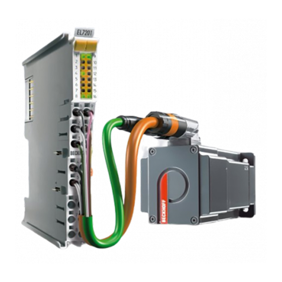
Product overview Product overview Introduction EL72x1 Fig. 9: EL7201 Fig. 10: EL7211 Version: 3.3 EL72x1... - Page 15 , 4.5 A ) with integrated resolver interface offer high servo performance with a very compact design. The EL72x1 was designed for the motor types of the AM31xx and AM81xx series from Beckhoff Automation. The fast control technology, based on field-orientated current and PI speed control, supports fast and highly dynamic positioning tasks.
-
Page 16: Technical Data
Product overview Technical data Technical data EL7201-000x EL7211-000x Number of outputs 3 motor phases, 2 resolver excitations, 2 motor holding brakes Number of inputs 2 (4) DC link voltages, 4 resolvers DC link supply voltage 8...50 V Supply voltage 24 V via the power contacts, via the E-bus Output current 4.5 A 2.8 A... -
Page 17: Technology
The EtherCAT servomotor terminal offers users the option to configure compact and cost-effective systems without having to give up the benefits of a servomotor. The Beckhoff servo terminal The EL72x1 is a fully capable servo drive for direct connection to servomotors in the lower performance range. - Page 18 Modern power semiconductors guarantee minimum power loss and enable feedback into the DC link when braking. Beckhoff sets new benchmarks with regard to size with the integration of a fully-featured servo drive in a standard EtherCAT terminal – the EL7201 – with a width of just 12 mm. This small manufactured size is possible thanks to the latest semiconductor technology and the resulting very high power factor.
-
Page 19: Start-Up
Product overview Fig. 12: Limitation to the rated motor current Start-up For commissioning: • mount the EL72x1-000x as described in the chapter Mounting and wiring [} 31] • configure the EL72x1-000x in TwinCAT as described in the chapter Commissioning [} 51]. EL72x1 Version: 3.3... -
Page 20: Basics Communication
Due to automatic cable detection (auto-crossing) symmetric (1:1) or cross-over cables can be used between EtherCAT devices from Beckhoff. Recommended cables Suitable cables for the connection of EtherCAT devices can be found on the Beckhoff web- site! Note E-Bus supply A bus coupler can supply the EL terminals added to it with the E-bus system voltage of 5 V;... -
Page 21: General Notes For Setting The Watchdog
Basics communication Fig. 13: System manager current calculation Malfunction possible! The same ground potential must be used for the E-Bus supply of all EtherCAT terminals in a terminal block! Attention General notes for setting the watchdog ELxxxx terminals are equipped with a safety feature (watchdog) that switches off the outputs after a specifiable time e.g. -
Page 22: Fig. 14 Ethercat Tab -> Advanced Settings -> Behavior -> Watchdog
Basics communication Fig. 14: EtherCAT tab -> Advanced Settings -> Behavior -> Watchdog Notes: • the multiplier is valid for both watchdogs. • each watchdog has its own timer setting, the outcome of this in summary with the multiplier is a resulting time. -
Page 23: Ethercat State Machine
Basics communication Example "Set SM watchdog" This checkbox enables manual setting of the watchdog times. If the outputs are set and the EtherCAT communication is interrupted, the SM watchdog is triggered after the set time and the outputs are erased. This setting can be used for adapting a terminal to a slower EtherCAT master or long cycle times. -
Page 24: Fig. 15 States Of The Ethercat State Machine
Basics communication Fig. 15: States of the EtherCAT State Machine Init After switch-on the EtherCAT slave in the Init state. No mailbox or process data communication is possible. The EtherCAT master initializes sync manager channels 0 and 1 for mailbox communication. Pre-Operational (Pre-Op) During the transition between Init and Pre-Op the EtherCAT slave checks whether the mailbox was initialized correctly. -
Page 25: Coe Interface
Basics communication Boot In the Boot state the slave firmware can be updated. The Boot state can only be reached via the Init state. In the Boot state mailbox communication via the file access over EtherCAT (FoE) protocol is possible, but no other mailbox communication and no process data communication. -
Page 26: Fig. 16 "Coe Online " Tab
Basics communication Fig. 16: "CoE Online " tab The figure above shows the CoE objects available in device "EL2502", ranging from 0x1000 to 0x1600. The subindices for 0x1018 are expanded. Data management and function "NoCoeStorage" Some parameters, particularly the setting parameters of the slave, are configurable and writeable. This can be done in write or read mode •... -
Page 27: Fig. 17 Startup List In The Twincat System Manager
Startup list Changes in the local CoE list of the terminal are lost if the terminal is replaced. If a terminal is replaced with a new Beckhoff terminal, it will have the default settings. It is therefore ad- Note visable to link all changes in the CoE list of an EtherCAT slave with the Startup list of the slave, which is processed whenever the EtherCAT fieldbus is started. -
Page 28: Fig. 18 Offline List
Basics communication Online/offline list While working with the TwinCAT System Manager, a distinction has to be made whether the EtherCAT device is "available", i.e. switched on and linked via EtherCAT and therefore online, or whether a configuration is created offline without connected slaves. In both cases a CoE list as shown in Fig. -
Page 29: Fig. 19 Online List
• Channel 1: parameter range 0x8010:00 ... 0x801F:255 • Channel 2: parameter range 0x8020:00 ... 0x802F:255 • ... This is generally written as 0x80n0. Detailed information on the CoE interface can be found in the EtherCAT system documentation on the Beckhoff website. EL72x1 Version: 3.3... -
Page 30: Distributed Clock
Basics communication Distributed Clock The distributed clock represents a local clock in the EtherCAT slave controller (ESC) with the following characteristics: • Unit 1 ns • Zero point 1.1.2000 00:00 • Size 64 bit (sufficient for the next 584 years; however, some EtherCAT slaves only offer 32-bit support, i.e. -
Page 31: Installation
Installation Installation Installation on mounting rails Risk of electric shock and damage of device! Bring the bus terminal system into a safe, powered down state before starting installation, disassembly or wiring of the Bus Terminals! WARNING Assembly Fig. 20: Attaching on mounting rail The Bus Coupler and Bus Terminals are attached to commercially available 35 mm mounting rails (DIN rails according to EN 60715) by applying slight pressure: 1. -
Page 32: Fig. 21 Disassembling Of Terminal
Installation Disassembly Fig. 21: Disassembling of terminal Each terminal is secured by a lock on the mounting rail, which must be released for disassembly: 1. Pull the terminal by its orange-colored lugs approximately 1 cm away from the mounting rail. In doing so for this terminal the mounting rail lock is released automatically and you can pull the terminal out of the bus terminal block easily without excessive force. -
Page 33: Fig. 22 Power Contact On Left Side
Installation Fig. 22: Power contact on left side Possible damage of the device Note that, for reasons of electromagnetic compatibility, the PE contacts are capacitatively coupled to the mounting rail. This may lead to incorrect results during insulation testing or Attention to damage on the terminal (e.g. -
Page 34: Installation Instructions For Enhanced Mechanical Load Capacity
Installation Installation instructions for enhanced mechanical load capacity Risk of injury through electric shock and damage to the device! Bring the Bus Terminal system into a safe, de-energized state before starting mounting, disassembly or wiring of the Bus Terminals! WARNING Additional checks The terminals have undergone the following additional tests: Verification... -
Page 35: Connection System
Installation Connection system Risk of electric shock and damage of device! Bring the bus terminal system into a safe, powered down state before starting installation, disassembly or wiring of the Bus Terminals! WARNING Overview The Bus Terminal system offers different connection options for optimum adaptation to the respective application: •... -
Page 36: Fig. 25 High Density Terminals
Installation The overview and nomenclature of the product names for KSxxxx and ESxxxx series has been retained as known from KLxxxx and ELxxxx series. High Density Terminals (HD Terminals) Fig. 25: High Density Terminals The Bus Terminals from these series with 16 connection points are distinguished by a particularly compact design, as the packaging density is twice as large as that of the standard 12 mm Bus Terminals. - Page 37 Installation Up to eight connections enable the connection of solid or finely stranded cables to the Bus Terminals. The terminals are implemented in spring force technology. Connect the cables as follows: 1. Open a spring-loaded terminal by slightly pushing with a screwdriver or a rod into the square opening above the terminal.
-
Page 38: Positioning Of Passive Terminals
Installation Positioning of passive Terminals Hint for positioning of passive terminals in the bus terminal block EtherCAT Terminals (ELxxxx / ESxxxx), which do not take an active part in data transfer within the bus terminal block are so called passive terminals. The passive terminals have Note no current consumption out of the E-Bus. -
Page 39: Installation Position For Operation With Or Without Fan
Installation Installation position for operation with or without fan Constraints regarding installation position and operating temperature range When installing the terminals ensure that an adequate spacing is maintained between other components above and below the terminal in order to guarantee adequate ventilation! Attention Prescribed installation position for operation without fan The prescribed installation position requires the mounting rail to be installed horizontally and the connection... -
Page 40: Fig. 30 Recommended Distances For Installation Position For Operation With Fan
Installation Fig. 30: Recommended distances for installation position for operation with fan Other installation positions Due to the enforced effect of the fan on the ventilation of the terminals, other installation positions (see Fig. “Other installation positions, example 1 + 2“) may be permitted where appropriate. See corresponding notes in the Technical Data of the terminal. -
Page 41: Fig. 32 Other Installation Positions, Example 2
Installation Fig. 32: Other installation positions, example 2 EL72x1 Version: 3.3... -
Page 42: Shielding Concept
Installation Shielding concept Together with the shield busbar, the prefabricated cables from Beckhoff Automation offer optimum protection against electromagnetic interference. It is highly recommended to apply the shield as close as possible to the terminal, in order to minimize operational disturbances. -
Page 43: Fig. 34 Shield Busbar Clamp
Installation Fig. 34: Shield busbar clamp Connect the cores 4 of the motor cable 5, then attach the copper-sheathed end 6 of the motor cable 5 with the shield clamp 7 to the shield busbar 3 or shield busbar clamp 3a. Tighten the screw 8 to the stop. Fasten the PE clamp 9 to the shield busbar 3 or shield busbar clamp 3a. - Page 44 Installation Connection of the feedback cable to the motor Twisting of the feedback cable cores The feedback cable cores should be twisted, in order to avoid operational disturbances. Note When screwing the feedback plug to the motor, the shield of the feedback cable is connected via the metallic plug fastener.
-
Page 45: Notes On Current Measurements Using Hall Sensors
Installation Notes on current measurements using Hall sensors The device described in this documentation features one or several integrated Hall sensor for the purpose of current measurements. During this process, the Hall sensor monitors the magnetic field generated by a current flowing through a conductor. -
Page 46: Leds And Connection
Installation LEDs and connection 5.8.1 EL7201-000x LEDs Fig. 37: EL7201-000x - LEDs Color Meaning green This LED indicates the terminal's operating state: State of the EtherCAT State Machine [} 75]: INIT = initialization of the terminal flashing State of the EtherCAT State Machine: BOOTSTRAP = function for firmware updates [} 179] rapidly of the terminal flashing... -
Page 47: Fig. 38 El7201-000X Connection
Installation Connection Fig. 38: EL7201-000x connection Terminal point Name Comment Ref + Resolver excitation + Sin + Resolver sine + Cos + Resolver cosine + Motor phase U Motor phase W Brake + Motor brake + 50 V DC link supply + (8...50 V) 50 V DC link supply + (8...50 V Ref -... -
Page 48: El7211-000X
Installation 5.8.2 EL7211-000x LEDs Fig. 39: EL7211-000x - LEDs Color Meaning green This LED indicates the terminal's operating state: State of the EtherCAT State Machine [} 75]: INIT = initialization of the terminal flashing State of the EtherCAT State Machine: BOOTSTRAP = function for firmware updates [} 179] rapidly of the terminal flashing... -
Page 49: Fig. 40 El7211-000X Connection
Installation Connection Fig. 40: EL7211-000x connection Terminal point Name Comment Resolver excit. + Resolver excitation + (R1) Resolver Sin + Resolver sine + (S2) Resolver Cos + Resolver cosine + (S1) Motor phase U Motor phase U Motor phase W Motor phase W Motor brake + Motor brake + DC supply +... -
Page 50: Fig. 41 Connection Resolver And Motor Cable
Installation Fig. 41: Connection resolver and motor cable Version: 3.3 EL72x1... -
Page 51: Commissioning
6.1.1 Installation of the TwinCAT real-time driver In order to assign real-time capability to a standard Ethernet port of an IPC controller, the Beckhoff real-time driver has to be installed on this port under Windows. This can be done in several ways. One option is described here. - Page 52 Commissioning Fig. 42: System Manager “Options” (TwinCAT 2) This have to be called up by the Menü “TwinCAT” within the TwinCAT 3 environment: Fig. 43: Call up under VS Shell (TwinCAT 3) The following dialog appears: Fig. 44: Overview of network interfaces Interfaces listed under “Compatible devices” can be assigned a driver via the “Install” button. A driver should only be installed on compatible devices.
- Page 53 Commissioning Fig. 45: EtherCAT device properties(TwinCAT 2): click on „Compatible Devices…“ of tab “Adapter” TwinCAT 3: the properties of the EtherCAT device can be opened by double click on “Device .. (EtherCAT)” within the Solution Explorer under “I/O”: After the installation the driver appears activated in the Windows overview for the network interface (Windows Start →...
- Page 54 Commissioning Fig. 47: Exemplary correct driver setting for the Ethernet port Other possible settings have to be avoided: Version: 3.3 EL72x1...
- Page 55 Commissioning Fig. 48: Incorrect driver settings for the Ethernet port EL72x1 Version: 3.3...
- Page 56 Commissioning IP address of the port used IP address/DHCP In most cases an Ethernet port that is configured as an EtherCAT device will not transport general IP packets. For this reason and in cases where an EL6601 or similar devices are Note used it is useful to specify a fixed IP address for this port via the “Internet Protocol TCP/IP”...
-
Page 57: Notes Regarding Esi Device Description
The files are read (once) when a new System Manager window is opened, if they have changed since the last time the System Manager window was opened. A TwinCAT installation includes the set of Beckhoff ESI files that was current at the time when the TwinCAT build was created. - Page 58 1018 in the configuration. This is also stated by the Beckhoff compatibility rule. Refer in particular to the chapter ‘General notes on the use of Beckhoff EtherCAT IO components’ and for manual configuration to the chapter ‘Offline configuration creation’ [} 62].
- Page 59 Commissioning Fig. 53: File OnlineDescription.xml created by the System Manager Is a slave desired to be added manually to the configuration at a later stage, online created slaves are indicated by a prepended symbol “>” in the selection list (see Figure “Indication of an online recorded ESI of EL2521 as an example”).
- Page 60 Commissioning Reasons may include: • Structure of the *.xml does not correspond to the associated *.xsd file → check your schematics • Contents cannot be translated into a device description → contact the file manufacturer Version: 3.3 EL72x1...
-
Page 61: Twincat Esi Updater
Commissioning 6.1.3 TwinCAT ESI Updater For TwinCAT 2.11 and higher, the System Manager can search for current Beckhoff ESI files automatically, if an online connection is available: Fig. 56: Using the ESI Updater (>= TwinCAT 2.11) The call up takes place under: “Options” → "Update EtherCAT Device Descriptions"... -
Page 62: Offline Configuration Creation
Commissioning • the devices/modules be connected to the power supply and ready for communication • TwinCAT must be in CONFIG mode on the target system. The online scan process consists of: • detecting the EtherCAT device [} 67] (Ethernet port at the IPC) •... - Page 63 Commissioning This query may appear automatically when the EtherCAT device is created, or the assignment can be set/ modified later in the properties dialog; see Fig. “EtherCAT device properties (TwinCAT 2)”. Fig. 61: EtherCAT device properties (TwinCAT 2) TwinCAT 3: the properties of the EtherCAT device can be opened by double click on “Device .. (EtherCAT)” within the Solution Explorer under “I/O”: Selecting the Ethernet port Ethernet ports can only be selected for EtherCAT devices for which the TwinCAT real-time...
- Page 64 (i.e. highest) revision and therefore the latest state of production is displayed in the selection dialog for Beckhoff devices. To show all device revisions available in the system as ESI descriptions tick the “Show Hidden Devices” check box, see Fig. “Display of previous revisions”.
- Page 65 If current ESI descriptions are available in the TwinCAT system, the last revision offered in the selection dialog matches the Beckhoff state of production. It is recommended to use the last device revision when creating a new configuration, if current Beckhoff devices are used in the real application. Older revisions should only be used if older devices from stock are to be used in the application.
- Page 66 Commissioning Fig. 67: EtherCAT terminal in the TwinCAT tree (left: TwinCAT 2; right: TwinCAT 3) Version: 3.3 EL72x1...
-
Page 67: Online Configuration Creation
Commissioning 6.1.6 ONLINE configuration creation Detecting/scanning of the EtherCAT device The online device search can be used if the TwinCAT system is in CONFIG mode. This can be indicated by a symbol right below in the information bar: • on TwinCAT 2 by a blue display “Config Mode” within the System Manager window: •... - Page 68 [} 72] with the defined initial configura- tion.Background: since Beckhoff occasionally increases the revision version of the deliv- ered products for product maintenance reasons, a configuration can be created by such a scan which (with an identical machine construction) is identical according to the device list;...
- Page 69 Likewise, A might create spare parts stores worldwide for the coming series-produced machines with EL2521-0025-1018 terminals. After some time Beckhoff extends the EL2521-0025 by a new feature C. Therefore the FW is changed, outwardly recognizable by a higher FW version and a new revision -1019. Nevertheless the new device naturally supports functions and interfaces of the predecessor version(s);...
- Page 70 Commissioning Fig. 75: Scan query after automatic creation of an EtherCAT device (left: TwinCAT 2; right: TwinCAT 3) Fig. 76: Manual triggering of a device scan on a specified EtherCAT device (left: TwinCAT 2; right: TwinCAT 3) In the System Manager (TwinCAT 2) or the User Interface (TwinCAT 3) the scan process can be monitored via the progress bar at the bottom in the status bar.
- Page 71 Commissioning Fig. 81: Online display example Please note: • all slaves should be in OP state • the EtherCAT master should be in “Actual State” OP • “frames/sec” should match the cycle time taking into account the sent number of frames •...
- Page 72 A ‘ChangeTo’ or ‘Copy’ should only be Attention carried out with care, taking into consideration the Beckhoff IO compatibility rule (see above). The device configuration is then replaced by the revision found; this can affect the supported process data and functions.
- Page 73 If current ESI descriptions are available in the TwinCAT system, the last revision offered in the selection dialog matches the Beckhoff state of production. It is recommended to use the last device revision when creating a new configuration, if current Beckhoff devices are used in the real application. Older revisions should only be used if older devices from stock are to be used in the application.
- Page 74 Commissioning Fig. 86: Correction dialog with modifications Once all modifications have been saved or accepted, click “OK” to transfer them to the real *.tsm configuration. Change to Compatible Type TwinCAT offers a function “Change to Compatible Type…” for the exchange of a device whilst retaining the links in the task.
-
Page 75: Ethercat Subscriber Configuration
Commissioning If called, the System Manager searches in the procured device ESI (in this example: EL1202-0000) for details of compatible devices contained there. The configuration is changed and the ESI-EEPROM is overwritten at the same time – therefore this process is possible only in the online state (ConfigMode). 6.1.7 EtherCAT subscriber configuration In the left-hand window of the TwinCAT 2 System Manager or the Solution Explorer of the TwinCAT 3... - Page 76 Commissioning „EtherCAT“ tab Fig. 91: „EtherCAT“ tab Type EtherCAT device type Product/Revision Product and revision number of the EtherCAT device Auto Inc Addr. Auto increment address of the EtherCAT device. The auto increment address can be used for addressing each EtherCAT device in the communication ring through its physical position.
- Page 77 For Beckhoff EtherCAT EL, ES, EM, EJ and EP slaves the following applies in general: • The input/output process data supported by the device are defined by the manufacturer in the ESI/XML description.
- Page 78 Commissioning Fig. 93: Configuring the process data Manual modification of the process data According to the ESI description, a PDO can be identified as “fixed” with the flag “F” in the PDO overview (Fig. “Configuring the process data”, J). The configuration of such PDOs Note cannot be changed, even if TwinCAT offers the associated dialog (“Edit”).
- Page 79 Commissioning Fig. 94: „Startup“ tab Column Description Transition Transition to which the request is sent. This can either be • the transition from pre-operational to safe-operational (PS), or • the transition from safe-operational to operational (SO). If the transition is enclosed in "<>" (e.g. <PS>), the mailbox request is fixed and cannot be modified or deleted by the user.
- Page 80 Commissioning Fig. 95: “CoE – Online” tab Object list display Column Description Index Index and sub-index of the object Name Name of the object Flags The object can be read, and data can be written to the object (read/write) The object can be read, but no data can be written to the object (read only) An additional P identifies the object as a process data object.
- Page 81 Commissioning Advanced The Advanced button opens the Advanced Settings dialog. Here you can specify which objects are displayed in the list. Fig. 96: Dialog “Advanced settings” Online - via SDO Information If this option button is selected, the list of the objects included in the object list of the slave is uploaded from the slave via SDO information.
- Page 82 Commissioning State Machine Init This button attempts to set the EtherCAT device to the Init state. Pre-Op This button attempts to set the EtherCAT device to the pre-operational state. This button attempts to set the EtherCAT device to the operational state. Bootstrap This button attempts to set the EtherCAT device to the Bootstrap state.
- Page 83 • DC-Synchron Advanced Settings… Advanced settings for readjustment of the real time determinant TwinCAT- clock Detailed information to Distributed Clocks are specified on http://infosys.beckhoff.com: Fieldbus Components → EtherCAT Terminals → EtherCAT System documentation → EtherCAT basics → Distributed Clocks 6.1.7.1...
- Page 84 Commissioning If an input is selected, the corresponding PDO assignment is displayed in the PDO Assignment list below. PDO Assignment PDO assignment of the selected Sync Manager. All PDOs defined for this Sync Manager type are listed here: • If the output Sync Manager (outputs) is selected in the Sync Manager list, all RxPDOs are displayed. •...
-
Page 85: Start-Up And Parameter Configuration
(Master: TwinCAT 2.11 R3) Installation of the latest XML device description Please ensure that you have installed the corresponding latest XML device description in TwinCAT. This can be downloaded from the Beckhoff Website and installed according to Note the installation instructions. - Page 86 Commissioning • Several parameters have to be set before the motor can be started up. The values can be found in section "Configuration of the main parameters [} 92]". Please set these parameters before continuing with the motor commissioning procedure. Adding an axis manually •...
- Page 87 Commissioning Fig. 103: Selecting and confirming the axis type • Left-click your axis to select it. Under the Settings tab select "Link To..." (see Fig. Linking the axis with the terminal). Fig. 104: Linking the axis with the terminal • Select the required terminal (CANopen DS402, EtherCAT CoE) and confirm with OK. Fig. 105: Selecting the right terminal •...
-
Page 88: Settings With The Drive Manager
Settings with the Drive Manager (Master TwinCAT 2.11 R3) The data provided in this section as an example refer to an AM3121-0200-0001 servomotor from Beckhoff Automation. For other motors the values may vary, depending on the application. Using the Drive Manager from revision -0019 The Drive Manager is only supported from revision -0019 [} 179] of the EL72x1. - Page 89 Commissioning Start-up with the Drive Manager • The terminal must already have been added manually under I/O devices or have been scanned in by the system (see section "Configuration set-up in TwinCAT [} 67]") • The terminal must already be integrated in the NC (see section "Integration in the NC configuration [} 85]") •...
- Page 90 Commissioning Fig. 109: List of available motors • Confirm the next dialog box with OK. All required parameters are automatically entered in the NC, and the scaling factor is calculated. If this is not confirmed, these settings have to be entered manually. See section "NC settings".
- Page 91 All main parameters for the commissioning the motor are now set. The motor can now be commissioned with the NC, for example. A brief description can be found in section "Commissioning the motor with the NC [} 112]". Or the NC can be addressed from the PLC. A small (download: (https://infosys.beckhoff.com/ content/1033/el72x1/Resources/zip/1958948107.zip)) is included in the documentation.
-
Page 92: Settings In The Coe Register
6.2.3 Settings in the CoE register (Master TwinCAT 2.11 R3) The data provided in this section as an example refer to an AM3121-0200-0001 servomotor from Beckhoff Automation. For other motors the values may vary, depending on the application. Version: 3.3... - Page 93 Inserting the motor XML file Downloading the EL72x1 motor XML files The motor XML files are available for download from the Beckhoff website. Note To facilitate commissioning of the EL72x1 servo terminal, motor XML files are provided for the servomotors that are supported by the EL72x1.
- Page 94 Commissioning Fig. 115: Selecting the correct motor XML file • All required parameters are then set, and the motor can be put into operation (see Fig. CoE parameters of the motor XML file). Fig. 116: CoE parameters of the motor XML file Startup list Any further application-specific settings should also be implemented in the Startup list.
- Page 95 Commissioning Adaptation of current and voltage The motor may overheat! In order to prevent overheating of the connected motor, it is important to adjust the voltage of the servo terminal to the actually connected voltage. Attention To this end set the index 0x8010:19 [} 137] "Nominal DC Link Voltage" of the connected voltage as required Setting further parameters Single-turn Bits (MDP742: Index 0x8000:12 [} 136] / DS402: Index 0x2010:12 [} 155]) / Multi-turn Bits (MDP742: Index 0x8000:13 [} 136] / DS402: Index 0x2010:13 [} 155])
-
Page 96: Application Example
EtherCAT XML Device Description The display matches that of the CoE objects from the EtherCAT XML Device Description. We recommend downloading the latest XML file from the download area of the Beckhoff Note website and installing it according to installation instructions. - Page 97 Commissioning Fig. 119: Selection of the target platform Please note the following for the System Manager file: • Start the System Manager in Config mode. • Please ensure that the I/O configuration matches your actual configuration. In the sample program only one EL7041 is integrated.
- Page 98 Commissioning • In the PLC configuration you have to adjust the path for the PLC program. Click on the appended PLC program and select the tab IEC1131 (see Fig. Changing the PLC path). Select Change and enter the correct path. Fig. 121: Changing the PLC path •...
- Page 99 Commissioning Once the global variables have been declared, programming can commence. Start with declaring local variables (see Fig. Local variables). MC_Direction is an enumeration type that specifies the direction of travel for the block MC_MoveVelocity, which in turn initiates continuous travel of the motor. An axis reset is carried out with the function block MC_Reset.
- Page 100 Commissioning Fig. 125: Program code The motor can then be operated with the aid of the following visualization (see Fig. Visualization). Press Enable to enable the axis. In "Free run mode" you can now use the Left or Right buttons, and the motor will run with a speed defined under fbMoveVelocity_Axis_1 in the selected direction.
-
Page 101: Commissioning Without Nc, Status Word/Control Word
Commissioning Fig. 126: Visualization Information on function blocks and data types Further information on the function blocks and data types used can be found in the Beck- hoff Information System. Note 6.2.5 Commissioning without NC, status word/control word (Master: TwinCAT 2.11 R3) In principle, the operating modes CST, CSTCA, CSV and CSP can be used without TwinCAT NC. - Page 102 Commissioning (Fault reset) (Shutdown) (Switch on) (Enable operation) Version: 3.3 EL72x1...
- Page 103 Commissioning Fig. 127: DS402 State Machine EL72x1 Version: 3.3...
- Page 104 Commissioning CST - cyclic synchronous torque Select Cyclic synchronous torque mode in index 0x7010:03 [} 144] Modes of operation (MDP) or 0x6060:0 [} 158] Modes of operation (DS402). The Predefined PDO Assignment: 'Cyclic synchronous torque mode (CST)' should also be selected in the respective process data (see CoE process data [} 130] or DS402 process data [} 133]).
-
Page 105: Homing
6.2.6 Homing (Master TwinCAT 2.11 R3) The data provided in this section as an example refer to an AM3121-0200-0001 servomotor from Beckhoff Automation. For other motors the values may vary, depending on the application. Table of contents • Referencing [} 105] - Function block "MC_Home"... - Page 106 Commissioning Fig. 129: Configuration of the MC_Home block • The following figure Extract from the functional description for MC_Home shows an extract from the functional description of MC_Home. Full information can be found in the corresponding functional description. Fig. 130: Extraction from the functional description for MC_Home Reference modes •...
-
Page 107: Nc Settings
Fig. 132: Setting the reference velocity 6.2.7 NC settings (Master TwinCAT 2.11 R3) The data provided in this section as an example refer to an AM3121-0200-0001 servomotor from Beckhoff Automation. For other motors the values may vary, depending on the application. EL72x1 Version: 3.3... -
Page 108: Fig. 133 Definition Of The Unit
Commissioning Table of contents • Definition of the unit [} 108] • Selecting the maximum velocity [} 108] • Dead time compensation [} 111] • Setting the encoder mask [} 109] • Scaling factor [} 110] - Calculation of the scaling factor [} 111] - Scaling output [} 111] •... -
Page 109: Fig. 134 Adjusting The Reference Velocity
Commissioning Fig. 134: Adjusting the reference velocity The reference velocity matches the maximum permitted velocity. Below that separate values for the maximum and minimum velocity for manual NC mode can be set. Setting the encoder mask The maximum values for the encoder mask can be set in the Parameter tab for the Axis1_ENC encoder settings. -
Page 110: Fig. 135 Setting The Encoder Mask
Commissioning Fig. 135: Setting the encoder mask Scaling factor The scaling factor can be changed by selecting "Axis 1_Enc" and tab "Parameter" in the NC (see Setting the Scaling Factor). The value can be calculated with the formulas specified below. The calculation is based on the assumption that one revolution corresponds to 360°. -
Page 111: Fig. 137 Dead Time Compensation Parameter
Commissioning Dead time compensation The dead time compensation can be adjusted on the Time Compensation tab of Axis1_ENC. It should theoretically be 3 cycles of the NC cycle time, although in practice 4 cycles are preferable. Therefore, the settings of the parameters Time Compensation Mode Encoder should be ‚ON (with velocity) )‘ and Encoder Delay in Cycles ‘4’. -
Page 112: Fig. 139 Lag Monitoring
Commissioning Fig. 139: Lag monitoring Commissioning the motor with the NC • Once the parameters are set, the motor is basically ready for operation. Individual further parameters have to be adapted to the respective application. • To commission the axis, activate the configuration (Ctrl+Shift+F4), select the axis, select tab Online and enable the axis under Set. -
Page 113: Operating Modes
Commissioning You can now move the axis with the function keys F1, F2 (Backward) or F3, F4 (Forward). You can adjust the Kv factor in order to approach a suitable factor. Set the value to 0 initially in order to set the correct reference velocity. -
Page 114: Csv
Commissioning CSV [} 114] - cyclic synchronous velocity (velocity control) In CSV mode the EL72x1-xxxx operates with the cyclic velocity interface. A defined velocity can be set via the Target velocity variable. CST [} 118] - cyclic synchronous torque (torque control) In CST mode the EL72x1-xxxx operates in the cyclic torque interface. A defined torque can be set via the Target torque variable. -
Page 115: Fig. 142 Selection Of The Mode Of Operation
Commissioning Fig. 142: Selection of the mode of operation • Under Predefined PDO assignment, also select Cyclic synchronous velocity mode (CSV), Fig. Selecting a predefined PDO assignment. EL72x1 Version: 3.3... -
Page 116: Fig. 143 Selecting A Predefined Pdo Assignment
Commissioning Fig. 143: Selecting a predefined PDO assignment • Activate the configuration (Ctrl+Shift+F4). • Run through the State Machine of the terminal. There are two ways to do this: ◦ If you use the TwinCAT NC. The State Machine is run through automatically by the NC. You can enable the axis in the Online tab of the axis. -
Page 117: Fig. 144 Set Enables
Commissioning Fig. 144: Set enables ◦ If you don’t use the TwinCAT NC. In this case you must run through the State Machine manually. To do this, follow the instructions in the chapter Commissioning without the NC [} 101]. • The cyclic variable Target velocity (Fig. Torque specification) can be used to specify a defined velocity. The value in the index 0x9010:14 (0x6090:0, DS402)Velocity encoder resolution corresponds to 1 rpm. -
Page 118: Cst
Commissioning 6.3.3 CST - cyclic synchronous torque (torque control) In CST mode the EL72x1-xxxx operates in the cyclic torque interface. A defined torque can be set via the Target torque variable. Step-by-Step • Add the terminal to the configuration as described in the chapter TwinCAT configuration settings [} 62] - manual or - Online scan [} 67]. -
Page 119: Fig. 147 Selecting A Predefined Pdo Assignment
Commissioning Fig. 147: Selecting a predefined PDO assignment • Activate the configuration (Ctrl+Shift+F4). • Run through the State Machine of the terminal. There are two ways to do this: ◦ If you use the TwinCAT NC. The State Machine is run through automatically by the NC. You can enable the axis in the Online tab of the axis. -
Page 120: Fig. 148 Set Enables
Commissioning Fig. 148: Set enables ◦ If you don’t use the TwinCAT NC. In this case you must run through the State Machine manually. To do this, follow the instructions in the chapter Commissioning without the NC [} 101]. • The cyclic variable Target torque (Fig. Torque specification) can be used to specify a defined torque. The value is specified in 1000ths of the rated current and the torque is calculated according to the following equation, where the rated current refers to the value in the index 0x8011:12 (rated current). -
Page 121: Cstca
Commissioning Fig. 149: Torque specification 6.3.4 CSTCA CSTCA - cyclic synchronous torque with commutation angle (torque control with commutation angle) This mode of operation is also intended for use with the cyclic torque interface. In addition the user can specify the commutation angle. The variable Commutation angle can be used to set an angle which is to be maintained with a defined torque set in variable Target torque. -
Page 122: Fig. 150 Selection Of The Mode Of Operation
Commissioning Fig. 150: Selection of the mode of operation • Under Predefined PDO assignment, also select Cyclic synchronous torque mode with commutation angle (CSTCA), Fig. Selecting a predefined PDO assignment. Version: 3.3 EL72x1... -
Page 123: Fig. 151 Selecting A Predefined Pdo Assignment
Commissioning Fig. 151: Selecting a predefined PDO assignment • Activate the configuration (Ctrl+Shift+F4). • Run through the State Machine of the terminal. There are two ways to do this: ◦ If you use the TwinCAT NC. The State Machine is run through automatically by the NC. You can enable the axis in the Online tab of the axis. -
Page 124: Fig. 152 Set Enables
Commissioning Fig. 152: Set enables ◦ If you don’t use the TwinCAT NC. In this case you must run through the State Machine manually. To do this, follow the instructions in the chapter Commissioning without the NC [} 101]. • You can specify a defined torque via the cyclic variable Target torque. The value is specified in 1000ths of the rated current and the torque is calculated according to the following equation, where the rated current refers to the value in the index 0x8011:12 (rated current). -
Page 125: Csp
Commissioning 6.3.5 CSP - cyclic synchronous position (position control) In the CSP operating mode the EL72x1-xxxx operates in the cyclic position interface. A defined position can be set via the Target position variable. Minimum cycle time The cycle times in CSP mode with 2^n * 125 µs (for n =1 to 8) are: 250 µs, 500 µs, 1 ms, 2 ms, 4 ms, 8 ms, 16 ms or 32 ms. -
Page 126: Fig. 155 Selecting A Predefined Pdo Assignment
Commissioning Fig. 155: Selecting a predefined PDO assignment • Activate the configuration (Ctrl+Shift+F4). • Run through the State Machine of the terminal. There are two ways to do this: ◦ If you use the TwinCAT NC. The State Machine is run through automatically by the NC. You can enable the axis in the “Online”... -
Page 127: Fig. 156 Set Enables
Commissioning Fig. 156: Set enables ◦ If you don’t use the TwinCAT NC. In this case you must run through the State Machine manually. To do this, follow the instructions in the chapter Commissioning without the NC [} 101]. • You can specify a defined position via the cyclic variable Target position (fig. Position specification). The value must be multiplied by the calculated scaling factor [} 110] in order to obtain the correct position. -
Page 128: Fig. 157 Position Specification
Commissioning Fig. 157: Position specification Following error monitor Furthermore, there is an option in CSP mode to activate a following error monitor. The following error monitor is switched off on delivery. In all other modes this is not used and is ignored. •... -
Page 129: Profile Mdp 742 Or Ds 402
The CoE objects in the MDP 742 profile (Modular Device Profile) are allocated in the way that is common for the Beckhoff EtherCAT Terminals. The DS402 drive profile is specified in IEC61800-7-200 (CiA402). It uses a different object directory structure. -
Page 130: Mdp742 Process Data
Commissioning MDP742 process data Table of contents • Sync Manager [} 130] • PDO Assignment [} 131] • Predefined PDO Assignment [} 132] Sync Manager (SM) Sync Manager (SM) The scope of the offered process data can be changed via the "Process Data" tab (see Fig. -
Page 131: Fig. 161 Process Data Tab Sm3, El72X1 (Default)
Commissioning Fig. 161: Process Data tab SM3, EL72x1 (default) PDO Assignment In order to configure the process data, select the desired Sync Manager (SM 2 & 3 can be edited) in the upper left-hand "Sync Manager" box (see fig.). The process data assigned to this Sync Manager can then be switched on or off in the “PDO Assignment”... -
Page 132: Fig. 162 Process Data Tab Predefined Pdo Assignment, El72X1
Commissioning SM3, PDO Assignment 0x1C13 Index Size (byte.bit) Name PDO content 0x1A05 DRV Info data 2 Index 0x6010:13 [} 143] 0x1A06 DRV Following error actual Index 0x6010:09 [} 143] value Table 1: PDO assignment of sync managers, EL72x1 Predefined PDO Assignment The "Predefined PDO Assignment" enables a simplified selection of the process data. The desired function is selected on the lower part of the "Process Data"... -
Page 133: Ds402 Process Data
Commissioning DS402 process data Table of contents • Sync Manager [} 133] • PDO Assignment [} 134] • Predefined PDO Assignment [} 135] Sync Manager (SM) Sync Manager (SM) The scope of the offered process data can be changed via the "Process Data" tab (see Fig. -
Page 134: Fig. 164 Process Data Tab Sm3, El72X1 (Default)
Commissioning Fig. 164: Process Data tab SM3, EL72x1 (default) PDO Assignment In order to configure the process data, select the desired Sync Manager (SM 2 & 3 can be edited) in the upper left-hand "Sync Manager" box (see fig.). The process data assigned to this Sync Manager can then be switched on or off in the “PDO Assignment”... -
Page 135: Fig. 165 Process Data Tab Predefined Pdo Assignment, El72X1
Commissioning Predefined PDO Assignment The "Predefined PDO Assignment" enables a simplified selection of the process data. The desired function is selected on the lower part of the "Process Data" tab. As a result, all necessary PDOs are automatically activated and the unnecessary PDOs are deactivated. Three PDO assignments are available: Name SM2, PDO assignment... -
Page 136: El72X1-0000 (Mdp742) - Object Description And Parameterization
EtherCAT XML Device Description The display matches that of the CoE objects from the EtherCAT XML Device Description. We recommend downloading the latest XML file from the download area of the Beckhoff Note website and installing it according to installation instructions. - Page 137 EL72x1-0000 (MDP742) - Object description and parameterization Index 8008 FB Resolver Settings Index (hex) Name Meaning Data type Flags Default 8008:0 FB Resolver Settings Maximum subindex UINT8 0x14 (20 8008:01 Invert feedback direc- Inverting the count direction BOOLEAN 0x00 (0 tion 8008:02 Enable automatic gain...
- Page 138 EL72x1-0000 (MDP742) - Object description and parameterization Index 8010 DRV Amplifier Settings Version: 3.3 EL72x1...
- Page 139 EL72x1-0000 (MDP742) - Object description and parameterization Index (hex) Name Meaning Data type Flags Default 8010:33 Stand still window Standstill window UINT16 0x0000 (0 Unit: rpm 8010:39 Select info data 1 Selection "Info data 1" UINT8 0x01 (1 Optional display of additional information in the cyclic process data.
- Page 140 EL72x1-0000 (MDP742) - Object description and parameterization Index (hex) Name Meaning Data type Flags Default 8010:52 Fault reaction option Possible values: UINT16 0x0000 (0 code 0: Disable drive function, motor is free to rotate 1: Slow down on slow down ramp 8010:53 Position loop propor- Proportional part of position controller...
-
Page 141: Configuration Data (Vendor-Specific)
EL72x1-0000 (MDP742) - Object description and parameterization Index 8012 DRV Brake Settings Index (hex) Name Meaning Data type Flags Default 8012:0 DRV Brake Settings Maximum subindex UINT8 0x14 (20 8012:01 Manual override (re- Manual release of the motor holding brake BOOLEAN 0x00 (0 lease) -
Page 142: Command Object
EL72x1-0000 (MDP742) - Object description and parameterization Command object Index FB00 DCM Command Index (hex) Name Meaning Data type Flags Default FB00:0 DCM Command Max. subindex UINT8 0x03 (3 FB00:01 Request 0x1000 Clear diag his- Clear the Diag History OCTET- tory STRING[2] 0x1100... - Page 143 EL72x1-0000 (MDP742) - Object description and parameterization Index 6010 DRV Inputs Index (hex) Name Meaning Data type Flags Default 6010:0 DRV Inputs Maximum subindex UINT8 0x13 (19 6010:01 Statusword UINT16 0x0000 (0 Statusword [} 101] Bit 0 : Ready to switch on Bit 1 : Switched on Bit 2 : Operation enabled Bit 3 : Fault...
-
Page 144: Output Data
EL72x1-0000 (MDP742) - Object description and parameterization Output data Index 7010 DRV Outputs Index (hex) Name Meaning Data type Flags Default 7010:0 DRV Outputs Maximum subindex UINT8 0x0E (14 7010:01 Controlword UINT16 0x0000 (0 Controlword [} 101] Bit 0 : Switch on Bit 1 : Enable voltage Bit 2 : reserved Bit 3 : Enable operation... -
Page 145: Information / Diagnosis Data
EL72x1-0000 (MDP742) - Object description and parameterization Information / diagnosis data Index 10F3 Diagnosis History Index (hex) Name Meaning Data type Flags Default 10F3:0 Diagnosis History Maximum subindex UINT8 0x37 (55 10F3:01 Maximum Messages Maximum number of stored messages UINT8 0x32 (50 A maximum of 50 messages can be stored 10F3:02... -
Page 146: Standard Objects
EL72x1-0000 (MDP742) - Object description and parameterization Index 9018 DRV Info data Index (hex) Name Meaning Data type Flags Default 9018:0 DRV Info data Maximum subindex UINT8 0x11 (17 9018:11 Auxiliary voltage (10 Auxiliary voltage UINT322 0x00000000 Unit: mV Index A010 DRV Amplifier Diag data Index (hex) Name Meaning Data type... - Page 147 EL72x1-0000 (MDP742) - Object description and parameterization Index 1018 Identity Index (hex) Name Meaning Data type Flags Default 1018:0 Identity Maximum subindex UINT8 0x04 (4 1018:01 Vendor ID Vendor ID of the EtherCAT slave UINT32 0x00000002 1018:02 Product code Product code of the EtherCAT slave UINT32 0x1C213052 (471937106...
- Page 148 EL72x1-0000 (MDP742) - Object description and parameterization Index 1605 DRV RxPDO-Map Torque offset Index (hex) Name Meaning Data type Flags Default 1605:0 DRV RxPDO-Map PDO Mapping RxPDO 6 UINT8 0x01 (1 Torque offset 1605:01 SubIndex 001 1. PDO Mapping entry (object 0x7010 (DRV Outputs), UINT32 0x7010:0A, 16 entry 0x0A (Torque offset))
- Page 149 EL72x1-0000 (MDP742) - Object description and parameterization Index 1A06 DRV TxPDO-Map Following error actual value Index (hex) Name Meaning Data type Flags Default 1A06:0 DRV TxPDO-Map Fol- PDO Mapping TxPDO 7 UINT8 0x01 (1 lowing error actual value 1A06:01 SubIndex 001 1.
- Page 150 EL72x1-0000 (MDP742) - Object description and parameterization Index 1C32 SM output parameter Index (hex) Name Meaning Data type Flags Default 1C32:0 SM output parameter Synchronization parameters for the outputs UINT8 0x20 (32 1C32:01 Sync mode Current synchronization mode: UINT16 0x0001 (1 •...
- Page 151 EL72x1-0000 (MDP742) - Object description and parameterization Index 1C33 SM input parameter Index (hex) Name Meaning Data type Flags Default 1C33:0 SM input parameter Synchronization parameters for the inputs UINT8 0x20 (32 1C33:01 Sync mode Current synchronization mode: UINT16 0x0000 (0 •...
- Page 152 EL72x1-0000 (MDP742) - Object description and parameterization Index F081 Download revision Index (hex) Name Meaning Data type Flags Default F081:0 Download revision Max. Subindex UINT8 0x01 (1 F010:01 Revision number Configured revision of the terminal, UINT32 0x00000000 see note [} 92] Version: 3.3 EL72x1...
-
Page 153: El72X1-0001 (Ds402) - Object Description And Parameterization
EtherCAT XML Device Description The display matches that of the CoE objects from the EtherCAT XML Device Description. We recommend downloading the latest XML file from the download area of the Beckhoff Note website and installing it according to installation instructions. -
Page 154: Configuration Data
EL72x1-0001 (DS402) - Object description and parameterization Configuration data Index 2002 Amplifier Settings Index (hex) Name Meaning Data type Flags Default 2002:0 Amplifier Settings Maximum subindex UINT8 0x41 (65 2002:11 Device type 1: Servo drive (cannot be changed) UINT32 0x00000001 2002:12 Current loop integral Current controller integral action time (Tn) - Page 155 EL72x1-0001 (DS402) - Object description and parameterization Index 2003 Motor Settings Index (hex) Name Meaning Data type Flags Default 2003:0 Motor Settings Maximum subindex UINT8 0x2D (45 2003:11 Max current Peak current UINT32 0x00001770 Unit: mA (6000 The adjustable motor current values can be interpreted as a peak value or RMS value.
-
Page 156: Configuration Data (Vendor-Specific)
EL72x1-0001 (DS402) - Object description and parameterization Index 2018 Resolver Settings Index (hex) Name Meaning Data type Flags Default 2018:0 Resolver Settings Maximum subindex UINT8 0x14 (20 2018:01 Invert feedback direc- Inverting the count direction BOOLEAN 0x00 (0 tion 2018:02 Enable automatic gain BOOLEAN 0x01 (1... -
Page 157: Command Object
EL72x1-0001 (DS402) - Object description and parameterization Command object Index FB00 Command Index Name Meaning Data type Flags Default (hex) FB00:0 Max. subindex UINT8 0x03 (3 Com- mand FB00:01 Request 0x1000 Clear diag history Clear the Diag History OCTET- STRING[2] 0x1100 Get build number Read out the build number... - Page 158 EL72x1-0001 (DS402) - Object description and parameterization Index 6040 Controlword Index (hex) Name Meaning Data type Flags Default 6040:0 Controlword UINT16 0x0000 (0 DS402 Controlword [} 101] Bit 0 : Switch on Bit 1 : Enable voltage Bit 2 : reserved Bit 3 : Enable operation Bit 4 - 6 : reserved Bit 7 : Fault reset...
- Page 159 EL72x1-0001 (DS402) - Object description and parameterization Index 6066 Following error time out Index (hex) Name Meaning Data type Flags Default 6066:0 Following error time Index 606C Velocity actual value Index (hex) Name Meaning Data type Flags Default 606C:0 Velocity actual value This object shall provide the actual velocity value INT32 0x00000000...
- Page 160 EL72x1-0001 (DS402) - Object description and parameterization Index 608F Position encoder resolution Index (hex) Name Meaning Data type Flags Default 608F:0 Position encoder reso- This object shall indicate the configured encoder incre- UINT8 0x02 (2 lution ments and number of motor revolutions. The position encoder resolution shall be calculated by the following formula: 608F:01...
-
Page 161: Information / Diagnosis Data
EL72x1-0001 (DS402) - Object description and parameterization Index 60FF Target velocity Index (hex) Name Meaning Data type Flags Default 60FF:0 Target velocity This object shall indicate the configured target velocity INT32 0x00000000 The velocity scaling can be found in object 0x6090 (Velocity encoder resolution) Index 6502 Supported drive modes Index (hex) Name... -
Page 162: Standard Objects
EL72x1-0001 (DS402) - Object description and parameterization Index 2030 Amplifier Diag data Index (hex) Name Meaning Data type Flags Default 2030:0 Amplifier Diag data Maximum subindex UINT8 0x11 (17 2030:11 Amplifier I2T tempera- I2T model load UINT8 0x00 (0 ture Unit: % Index 2031 Motor Diag data Index (hex) Name... - Page 163 EL72x1-0001 (DS402) - Object description and parameterization Index 1008 Device name Index (hex) Name Meaning Data type Flags Default 1008:0 Device name Device name of the EtherCAT slave STRING EL72x1-0001 Index 1009 Hardware version Index (hex) Name Meaning Data type Flags Default 1009:0...
- Page 164 EL72x1-0001 (DS402) - Object description and parameterization Index 1604 DS402 RxPDO-Map Torque limitation Index (hex) Name Meaning Data type Flags Default 1604:0 DS402 RxPDO-Map PDO Mapping RxPDO 5 UINT8 0x01 (1 Torque limitation 1604:01 SubIndex 001 1. PDO Mapping entry (object 0x6072 (Max torque), UINT32 0x6072:00, 16 entry 0x00 (Max torque))
- Page 165 EL72x1-0001 (DS402) - Object description and parameterization Index 1C00 Sync manager type Index (hex) Name Meaning Data type Flags Default 1C00:0 Sync manager type Using the sync managers UINT8 0x04 (4 1C00:01 SubIndex 001 Sync-Manager Type Channel 1: Mailbox Write UINT8 0x01 (1 1C00:02...
- Page 166 EL72x1-0001 (DS402) - Object description and parameterization Index 1C32 SM output parameter Index (hex) Name Meaning Data type Flags Default 1C32:0 SM output parameter Synchronization parameters for the outputs UINT8 0x20 (32 1C32:01 Sync mode Current synchronization mode: UINT16 0x0000 (0 •...
- Page 167 EL72x1-0001 (DS402) - Object description and parameterization Index 1C33 SM input parameter Index (hex) Name Meaning Data type Flags Default 1C33:0 SM input parameter Synchronization parameters for the inputs UINT8 0x20 (32 1C33:01 Sync mode Current synchronization mode: UINT16 0x0000 (0 •...
-
Page 168: Error Correction
The DiagMessages are explained in text form in the ESI/XML file belonging to the EtherCAT device: on the basis of the Text ID contained in the DiagMessage, the corresponding plain text message can be found in the languages contained in the ESI/XML. In the case of Beckhoff products these are usually German and English. -
Page 169: Fig. 167 Implementation Of The Diagmessage System In The Twincat System Manager
Error correction Support for commissioning The DiagMessages system is to be used above all during the commissioning of the plant. The diagnostic values e.g. in the StatusWord of the device (if available) are helpful for on- Note line diagnosis during the subsequent continuous operation. TwinCAT System Manager implementation From TwinCAT 2.11 DiagMessages, if available, are displayed in the device’s own interface. - Page 170 Structure of the Text ID The structure of the MessageID is not subject to any standardization and can be supplier-specifically defined. In the case of Beckhoff EtherCAT devices (EL, EP) it usually reads according to xyzz: 0: Systeminfo 0: System...
- Page 171 Error correction Text ID Type Place Text Message Additional comment 0x0001 Information System No error No error 0x0002 Information System Communication estab- Connection established lished 0x0003 Information System Initialization: 0x%X, 0x General information; parameters depend on event. %X, 0x%X See device documentation for interpretation. 0x1000 Information System...
- Page 172 Error correction Text ID Type Place Text Message Additional comment 0x2000 Information System %s: %s 0x2001 Information System %s: Network link lost Network connection lost 0x2002 Information System %s: Network link de- Network connection found tected 0x2003 Information System %s: no valid IP Configu- Invalid IP configuration ration - Dhcp client started...
- Page 173 Error correction Text ID Type Place Text Message Additional comment 0x4000 Warning Warning: 0x%X, 0x%X, General warning; parameters depend on event. See 0x%X device documentation for interpretation. 0x4001 Warning System Warning: 0x%X, 0x%X, 0x%X 0x4002 Warning System %s: %s Connection Open (IN:%d OUT:%d API:%dms) from %d.%d.
- Page 174 Error correction Text ID Type Place Text Message Additional comment 0x4414 Warning Drive I2T-Model Motor over- - The motor is being operated outside the parameter- load (Warning) ized rated values - The I2T-model of the motor is incorrectly parameter- ized 0x4415 Warning Drive...
- Page 175 Error correction Text ID Type Place Text Message Additional comment 0x8000 Error System %s: %s 0x8001 Error System Error: 0x%X, 0x%X, 0x General error; parameters depend on event. See de- vice documentation for interpretation. 0x8002 Error System Communication aborted Communication aborted 0x8003 Error System...
- Page 176 Error correction Text ID Type Place Text Message Additional comment 0x8288 Error Communication Reading Certificate EK failed: %X 0x8289 Error Communication Challenge could not be hashed: %X 0x828A Error Communication Tickstamp Process failed 0x828B Error Communication PCR Process failed: %X 0x828C Error Communication Quote Process failed:...
-
Page 177: Notes On Diag Messages Associated With Motor Terminals
Error correction Text ID Type Place Text Message Additional comment 0x841C Error Drive STO while the axis was An attempt was made to activate the axis, despite the enabled fact that no voltage is present at the STO input. 0x8550 Error Inputs Zero crossing phase %X... -
Page 178: Appendix
Beckhoff EtherCAT modules are intended for use with Beckhoff’s UL Listed EtherCAT Sys- tem only. Examination For cULus examination, the Beckhoff I/O System has only been investigated for risk of fire and electrical shock (in accordance with UL508 and CSA C22.2 No. 142). For devices with Ethernet connectors Not for connection to telecommunication circuits. -
Page 179: Ethercat Al Status Codes
Check on the Beckhoff web page whether more up-to-date documentation is available. 10.4 Firmware Update EL/ES/EM/EPxxxx This section describes the device update for Beckhoff EtherCAT slaves from the EL/ES, EM, EK and EP series. A firmware update should only be carried out after consultation with Beckhoff support. Storage locations An EtherCAT slave stores operating data in up to 3 locations: •... -
Page 180: Device Description Esi File/Xml
EtherCAT communication is set up accordingly. The device description is available from the download area of the Beckhoff website at (http://www.beckhoff.de). All ESI files are accessible there as zip files. Customers can access the data via the EtherCAT fieldbus and its communication mechanisms. Acyclic mailbox communication or register access to the ESC is used for updating or reading of these data. -
Page 181: Fig. 168 Device Identifier Consisting Of Name El3204-0000 And Revision -0016
Corresponding updates Note should only be carried out in consultation with Beckhoff support. Display of ESI slave identifier The simplest way to ascertain compliance of configured and actual device description is to scan the EtherCAT boxes in TwinCAT mode Config/FreeRun: Fig. 169: Scan the subordinate field by right-clicking on the EtherCAT device... -
Page 182: Fig. 170 Configuration Is Identical
Appendix Fig. 170: Configuration is identical otherwise a change dialog appears for entering the actual data in the configuration. Fig. 171: Change dialog In this example in Fig. Change dialog, an EL3201-0000-0017 was found, while an EL3201-0000-0016 was configured. In this case the configuration can be adapted with the Copy Before button. The Extended Information checkbox must be set in order to display the revision. -
Page 183: Firmware Explanation
10.4.2 Firmware explanation Determining the firmware version Determining the version on laser inscription Beckhoff EtherCAT slaves feature serial numbers applied by laser. The serial number has the following structure: KK YY FF HH EL72x1 Version: 3.3... -
Page 184: Updating Controller Firmware *.Efw
This CoE directory can only be displayed if a slave is connected and operational. • offline: The EtherCAT Slave Information ESI/XML may contain the default content of the CoE. This CoE directory can only be displayed if it is included in the ESI (e.g. "Beckhoff EL5xxx.xml"). -
Page 185: Fig. 175 Firmware Update
Switch to the Online tab to update the controller firmware of a slave, see Fig. Firmware Update. Fig. 175: Firmware Update Proceed as follows, unless instructed otherwise by Beckhoff support. Valid for TwinCAT 2 and 3 as EtherCAT master. • Switch TwinCAT system to ConfigMode/FreeRun with cycle time >= 1 ms (default in ConfigMode is 4 ms). -
Page 186: Fpga Firmware *.Rbf
Appendix • Switch slave to BOOTSTRAP • Check the current status (B, C) • Download the new *efw file (wait until it ends). A pass word will not be neccessary usually. • After the download switch to INIT, then PreOP •... -
Page 187: Fig. 176 Fpga Firmware Version Definition
Appendix Fig. 176: FPGA firmware version definition If the column Reg:0002 is not displayed, right-click the table header and select Properties in the context menu. Fig. 177: Context menu Properties The Advanced Settings dialog appears where the columns to be displayed can be selected. Under Diagnosis/Online View select the '0002 ETxxxx Build' check box in order to activate the FPGA firmware version display. - Page 188 Older firmware versions can only be updated by the manufacturer! Updating an EtherCAT device The following sequence order have to be met if no other specifications are given (e.g. by the Beckhoff support): • Switch TwinCAT system to ConfigMode/FreeRun with cycle time >= 1 ms (default in ConfigMode is 4 ms).
- Page 189 Appendix • In the TwinCAT System Manager select the terminal for which the FPGA firmware is to be updated (in the example: Terminal 5: EL5001) and click the Advanced Settings button in the EtherCAT tab: • The Advanced Settings dialog appears. Under ESC Access/E²PROM/FPGA click on Write FPGA button: EL72x1 Version: 3.3...
-
Page 190: Simultaneous Updating Of Several Ethercat Devices
Appendix • Select the file (*.rbf) with the new FPGA firmware, and transfer it to the EtherCAT device: • Wait until download ends • Switch slave current less for a short time (don't pull under voltage!). In order to activate the new FPGA firmware a restart (switching the power supply off and on again) of the EtherCAT device is required. -
Page 191: Restoring The Delivery State
Appendix 10.5 Restoring the delivery state To restore the delivery state for backup objects in ELxxxx terminals, the CoE object Restore default parameters, SubIndex 001 can be selected in the TwinCAT System Manager (Config mode) (see Fig. Selecting the Restore default parameters PDO) Fig. 180: Selecting the Restore default parameters PDO Double-click on SubIndex 001 to enter the Set Value dialog. -
Page 192: Support And Service
Beckhoff's branch offices and representatives Please contact your Beckhoff branch office or representative for local support and service on Beckhoff products! The addresses of Beckhoff's branch offices and representatives round the world can be found on her internet pages: http://www.beckhoff.com You will also find further documentation for Beckhoff components there. - Page 193 Table of figures Table of figures Fig. 1 EL5021 EL terminal, standard IP20 IO device with serial/ batch number and revision ID (since 2014/01)............................Fig. 2 EK1100 EtherCAT coupler, standard IP20 IO device with serial/ batch number......Fig. 3 CU2016 switch with serial/ batch number..................Fig.
- Page 194 Table of figures Fig. 42 System Manager “Options” (TwinCAT 2)..................Fig. 43 Call up under VS Shell (TwinCAT 3) ................... Fig. 44 Overview of network interfaces ....................Fig. 45 EtherCAT device properties(TwinCAT 2): click on „Compatible Devices…“ of tab “Adapter” ..Fig. 46 Windows properties of the network interface................
- Page 195 Table of figures Fig. 86 Correction dialog with modifications ................... Fig. 87 Dialog “Change to Compatible Type…” (left: TwinCAT 2; right: TwinCAT 3) ......Fig. 88 TwinCAT 2 Dialog Change to Alternative Type ................Fig. 89 Branch element as terminal EL3751.................... Fig. 90 “General”...
- Page 196 Table of figures Fig. 132 Setting the reference velocity ...................... 107 Fig. 133 Definition of the unit ........................108 Fig. 134 Adjusting the reference velocity....................109 Fig. 135 Setting the encoder mask ......................110 Fig. 136 Setting the Scaling Factor......................110 Fig.
- Page 197 Table of figures Fig. 178 Dialog Advanced Settings ......................188 Fig. 179 Multiple selection and firmware update ..................190 Fig. 180 Selecting the Restore default parameters PDO................191 Fig. 181 Entering a restore value in the Set Value dialog................191 EL72x1 Version: 3.3...
Need help?
Do you have a question about the EL72 1 Series and is the answer not in the manual?
Questions and answers