
Related Manuals for Beckhoff TwinSAFE EL6910


Summary of Contents for Beckhoff TwinSAFE EL6910
- Page 1 Operation Manual for EL6910 TwinSAFE Logic Terminal Version: 1.8.0 Date: 2019-01-09...
-
Page 3: Table Of Contents
Documentation issue status ...................... 8 Version history of the TwinSAFE product .................. 9 References ............................ 10 2 TwinSAFE System Description ...................... 11 Extension of the Beckhoff I/O system with safety functions ............ 11 Safety concept .......................... 11 3 Product description.......................... 12 EL6910 - TwinSAFE logic terminal .................... 12 Intended use ............................ 13... - Page 4 Table of contents 4.5.2 Info data for function blocks..................... 91 4.5.3 Info data for the TwinSAFE group ................... 92 4.5.4 Info data for the device .................... 93 Version history .......................... 93 User Administration ......................... 94 Backup/Restore .......................... 97 Export/import of the safety project .................... 100 4.10 Diag History tab .......................... 102 4.11 Configuration of the PROFIsafe slave ................... 103 4.11.1...
-
Page 5: Foreword
Product features Only the product features specified in the current user documentation are valid. Further information given on the product pages of the Beckhoff homepage, in emails or in other publications is not authoritative. Disclaimer The documentation has been prepared with care. The products described are subject to cyclical revision. For that reason the documentation is not in every case checked for consistency with performance data, standards or other characteristics. -
Page 6: Safety Instructions
Offenders will be held liable for the payment of damages. All rights reserved in the event of the grant of a patent, utility model or design. Delivery conditions In addition, the general delivery conditions of the company Beckhoff Automation GmbH & Co. KG apply. Safety instructions 1.2.1... -
Page 7: Description Of Safety Symbols
Foreword 1.2.3 Description of safety symbols In these operating instructions the following instructions are used. These instructions must be read carefully and followed without fail! DANGER Serious risk of injury! Failure to follow this safety instruction directly endangers the life and health of persons. WARNING Risk of injury! Failure to follow this safety instruction endangers the life and health of persons. -
Page 8: Documentation Issue Status
Foreword Documentation issue status Version Comment 1.8.0 • Description Multiple Download added • Note added to Project Settings • Description of mounting rail installation updated 1.7.0 • Note added to Customizing • Description of firmware update added • Version history of the TwinSAFE product added •... -
Page 9: Version History Of The Twinsafe Product
Foreword Version Comment 0.5.0 • Descriptions of external connections, properties of FB ports, parameterization of Alias Devices, Variable Mapping and Customizing updated 0.4.0 • Description of the group sequence added • Check Safe Addresses description added 0.3.0 • System description added 0.2.0 •... -
Page 10: References
Foreword References Version Title / description 3.1.0 or newer Documentation – TwinSAFE Logic FB This document describes the safety-related function blocks that are available in the TwinSAFE Logic and form the safety-related application. 1.8.0 or newer TwinSAFE Application Guide The application guide provides the user with examples for the calculation of safety parameters for safety functions according to the standards DIN EN ISO 13849-1 and EN 62061 or EN 61508:2010 (if applicable), such as are typically used on machines. -
Page 11: Twinsafe System Description
Extension of the Beckhoff I/O system with safety functions The TwinSAFE products from Beckhoff enable convenient expansion of the Beckhoff I/O system with safety components, and integration of all the cabling for the safety circuit within the existing fieldbus cable. Safe signals can be mixed with standard signals as required. -
Page 12: Product Description
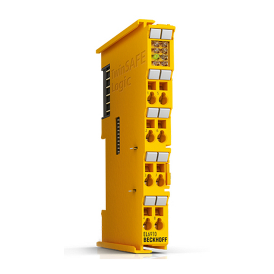
Product description Product description EL6910 - TwinSAFE logic terminal The TwinSAFE Logic terminal is the link unit between the TwinSAFE inputs and outputs. The EL6910 meets the requirements of EN 62061:2005/A2:2015 and EN 61508:2010 SIL 3, EN 81-20:2014, EN 81-22:2014, EN 81-50:2014 and EN ISO 13849-1:2015 (Cat 4, PL e). Fig. 1: EL6910 - TwinSAFE Logic terminal Version: 1.8.0 EL6910... -
Page 13: Intended Use
TwinSAFE components may only be used for the purposes described below! The TwinSAFE terminals expand the application range of Beckhoff Bus Terminal system with functions that enable them to be used for machine safety applications. The TwinSAFE terminals are designed for machine safety functions and directly associated industrial automation tasks. - Page 14 Product description CAUTION Note on approval according to EN 81-20, EN 81-22 and EN 81-50 • The TwinSAFE components may only be used in machines that have been designed and installed in ac- cordance with the requirements of the EN 60204-1 standard. •...
-
Page 15: Technical Data
Product description Technical data Product designation EL6910 Number of inputs Number of outputs Status display 4 diagnostic LEDs Minimum/maximum cycle time approx. 1 ms / according the project size Fault response time ≤ watchdog times Watchdog time min. 2 ms, max. 60000 ms Input process image Dynamic, according to the TwinSAFE configuration in TwinCAT 3 Output process image... -
Page 16: Safety Parameters
Product description Safety parameters Characteristic numbers EL6910 Lifetime [a] Proof test interval [a] not required 1.79E-09 %SIL3 of PFH 1.79% 2.54E-05 %SIL3 of PFD 2.54% MTTF high high Performance level PL e Category Classification element Type B 1. Special proof tests are not required during the entire service life of the EL6910 EtherCAT Terminal. 2. -
Page 17: Dimensions
Product description Dimensions Fig. 2: Dimensions of the EL6910 Width: 12 mm (side-by-side installation) Height: 100 mm Depth: 68 mm EL6910 Version: 1.8.0... -
Page 18: Operation
Operation Operation Environmental conditions Please ensure that the TwinSAFE components are only transported, stored and operated under the specified conditions (see technical data)! WARNING Risk of injury! The TwinSAFE components must not be used under the following operating conditions. • under the influence of ionizing radiation (that exceeds the level of the natural environmental radiation) •... -
Page 19: Fig. 3 Installation Position And Minimum Distances
Operation 4.2.3.1 Control cabinet / terminal box The TwinSAFE terminals must be installed in a control cabinet or terminal box with IP54 protection class according to IEC 60529 as a minimum. 4.2.3.2 Installation position and minimum distances For the prescribed installation position the mounting rail is installed horizontally and the mating surfaces of the EL/KL terminals point toward the front (see illustration below). -
Page 20: Fig. 4 Sample Configuration For Temperature Measurement
Operation 4.2.3.3 Sample configuration for temperature measurement Fig. 4: Sample configuration for temperature measurement The sample configuration for the temperature measurement consists of an EK1100 EtherCAT coupler with connected terminals that match the typical distribution of digital and analog signal types at a machine. On the EL6910 a safety project is active, which reads safe inputs and enables all 4 safe outputs during the measurement. -
Page 21: Fig. 5 Installation On The Mounting Rail
Operation 4.2.3.4 Installation on mounting rails WARNING Risk of electric shock and damage of device! Bring the bus terminal system into a safe, powered down state before starting installation, disassembly or wiring of the Bus Terminals! Mounting Fig. 5: Installation on the mounting rail The Bus Couplers and Bus Terminals are attached to commercially available 35 mm mounting rails (DIN rail according to EN 60715) by applying slight pressure: 1. -
Page 22: Fig. 6 Removal From Mounting Rail
Operation Disassembly Fig. 6: Removal from mounting rail Each terminal is secured by a lock on the mounting rail, which must be released for disassembly: 1. Pull down the terminal at its orange-colored straps from the mounting rail by approx. 1 cm. The rail locking of this terminal is automatically released, and you can now pull the terminal out of the Bus Ter- minal block with little effort. - Page 23 Operation 4.2.3.5 Notes on the arrangement of TwinSAFE components The following notes show favorable and unfavorable arrangement of the terminals in relation to thermal aspects. Components with higher waste heat are marked with a red symbol and components with low waste heat with a blue symbol EtherCAT coupler EK11xx and power supply terminal EL9410 The more terminals are connected behind an EtherCAT coupler or a power supply terminal, the higher is the...
-
Page 24: Fig. 7 Thermally Unfavorable Arrangement Of The Twinsafe Terminals
Operation Thermally unfavorable arrangement of the TwinSAFE terminals The following structure is rather unfavorable, since terminals with rather high waste heat are connected directly to couplers or power supply terminals with high E-Bus load. The additional external heating of the TwinSAFE terminals by the adjacent power supply units increases the internal terminal temperature, which can lead to the maximum permissible temperature being exceeded. -
Page 25: Electrical Installation
Operation Thermally favorable arrangement of the TwinSAFE terminals The following structure is thermally favorable, since between the coupler / power supply terminal and terminals with rather high waste heat, terminals with low current consumption and thus rather low waste heat are placed. -
Page 26: Fig. 9 Pe Power Contact
Operation Note the connection of the power contacts During the design of a Bus Terminal block, the pin assignment of the individual Bus Terminals must be taken account of, since some types (e.g. analog Bus Terminals or digital 4-channel Bus Termi- nals) do not or not fully loop through the power contacts. -
Page 27: Fig. 10 El6900/El6910 Pin Assignment
Operation 4.2.4.3 EL6900/EL6910 pin assignment Fig. 10: EL6900/EL6910 pin assignment Terminal point Output Signal not used, no function not used, no function not used, no function not used, no function not used, no function not used, no function not used, no function not used, no function EL6910 Version: 1.8.0... -
Page 28: Twinsafe Reaction Times
Operation 4.2.5 TwinSAFE reaction times The TwinSAFE terminals form a modular safety system that exchanges safety-oriented data via the Safety- over-EtherCAT protocol. This chapter is intended to help you determine the system's reaction time from the change of signal at the sensor to the reaction at the actuator. Typical reaction time The typical reaction time is the time that is required to transmit information from the sensor to the actuator, if the overall system is working without error in normal operation. -
Page 29: Fig. 12 Worst-Case Reaction Time
Operation Fig. 12: Worst-case reaction time This assumes that a signal change occurs at the sensor and is transmitted to the input. A communication error occurs at precisely the moment when the signal is to be transferred to the communication interface. This is detected by the logic following the watchdog time of the communication link. -
Page 30: Operation In Potentially Explosive Atmospheres (Atex)
80°C at the wire branching points, then cables must be selected whose temperature data correspond to the actual measured temperature values! Observe the permissible ambient temperature range of 0 to 55 °C when using Beckhoff fieldbus compo- nents in potentially explosive atmospheres! -
Page 31: Date Code And Serial Number
In addition the TwinSAFE terminals bear a unique serial number. 4.3.4 Further ATEX documentation Please also refer to the further documentation Notes regarding application of the Bus Terminal system in areas potentially explosive atmosphere are available in the Download section of the Beckhoff website at http://www.beckhoff.de. EL6910 Version: 1.8.0... -
Page 32: Configuration Of The Terminal In Twincat
Adding an EtherCAT Terminal See TwinCAT 3 automation software documentation. 4.4.4 Adding an EL6910 An EL6910 is added in exactly the same way as any other Beckhoff EtherCAT Terminal. In the list, open Safety Terminals and select the EL6910. Version: 1.8.0 EL6910... -
Page 33: Fig. 13 Adding An El6910
Operation Fig. 13: Adding an EL6910 Size of the process image The process image of the EL6910 is adjusted dynamically, based on the TwinSAFE configuration created in TwinCAT 3. EL6910 Version: 1.8.0... -
Page 34: Address Settings On Twinsafe Terminals With 1023 Possible Addresses
Operation 4.4.5 Address settings on TwinSAFE terminals with 1023 possible addresses Fig. 14: Address settings on TwinSAFE terminals with 1023 possible addresses The TwinSAFE address of the terminal is set via the 10-way DIP switch on the left-hand side of the TwinSAFE terminal. -
Page 35: Creating A Safety Project In Twincat 3
4.4.6 Creating a safety project in TwinCAT 3 Further documentation Information on TwinSAFE function blocks, groups and connections can be found in the TwinSAFE Logic FB documentation on the Beckhoff website under http://www.beckhoff.com/english/download/twinsafe.htm. 4.4.6.1 Add new item In TwinCAT 3 a new project can be created via Add New Item… in the context menu of the Safety node. -
Page 36: Fig. 17 Twincat Safety Project Wizard
Operation Fig. 17: TwinCAT Safety Project Wizard 4.4.6.3 Target System Once the project has been created with the project wizard, the safety project can be assigned to the physical TwinSAFE terminal EL6910 by selecting the Target System node. Fig. 18: Selecting the Target System node Set the target system to EL6910 via the drop-down list and link it with the EL6910 terminal via the Link button next to Physical Device. -
Page 37: Fig. 19 Linking Of Target System And Twinsafe Terminal
Operation Fig. 19: Linking of target system and TwinSAFE terminal 4.4.6.4 Alias devices The communication between the safety logic and the I/O level is realized via an alias level. At this alias level (subnode Alias Devices) corresponding alias devices are created for all safe inputs and outputs, and also for standard signal types. -
Page 38: Fig. 21 Selection From The I/O Tree
Operation Fig. 21: Selection from the I/O tree The alias devices are created in the safety project when the dialog is closed via OK. Alternatively, the user can create the alias devices individually. To this end select Add and New item from the context menu, followed by the required device. -
Page 39: Fig. 23 Alias Device In The Safety Project Structure
Operation 4.4.6.5 Parameterization of the alias device The settings can be opened by double-clicking on the Alias Device in the safety project structure. Fig. 23: Alias Device in the safety project structure The Linking tab contains the FSoE address, the checkbox for setting as External Device and the link to the physical I/O device. -
Page 40: Fig. 26 Selecting An Alias Device
Operation Parameter Description User inter- action re- quired Conn. no. Connection number - automatically assigned by the TwinCAT system Conn ID Connection ID: preallocated by the system, but can be changed by the user. A Check Conn ID must be unique within a configuration. Duplicate connection IDs result in an error message. -
Page 41: Fig. 27 Safety Parameter For The Device
Operation Fig. 27: Safety parameter for the device 4.4.6.6 Connection to AX5805/AX5806 There are separate dialogs for linking an AX5805 or AX5806 TwinSAFE Drive option card, which can be used to set the safety functions of the AX5000 safety drive options. Creating and opening of an alias device for an AX5805 results in five tabs;... -
Page 42: Fig. 29 Ax5000 Safety Drive Options - General Ax5805 Settings
Operation Fig. 29: AX5000 safety drive options - general AX5805 settings The Process Image tab can be used to set the different safety functions for the AX5805. Fig. 30: AX5000 safety drive options - Process Image The parameters under the General AX5805 Settings and Process Image tabs are identical to the parameters under the Safety Parameters tab. -
Page 43: Fig. 31 Ax5000 Safety Drive Options - Function Diagram
Operation Fig. 31: AX5000 safety drive options - Function Diagram 4.4.6.7 External connection An external Custom FSoE Connection can be created for a connection to a further EL69x0, EJ6910, KL6904 or third-party device. If a dedicated ESI file exists for a third-party device, the device is listed as a selectable safety device, and the Custom FSoE Connection option is not required. -
Page 44: Fig. 32 Creating An External Connection (Custom Fsoe Connection)
Operation Fig. 32: Creating an external connection (Custom FSoE Connection) Before the connection can be used and linked further, the process image size must be parameterized. This can be set under the Process Image tab. Suitable data types for different numbers of safety data are provided in the dropdown lists for the input and output parameters. -
Page 45: Fig. 34 Renaming The Individual Signals Within The Telegram
Operation Fig. 34: Renaming the individual signals within the telegram The connection is linked under the Linking tab. The Link button next to Full Name (input) and Full Name (output) can be used to select the corresponding variable. Fig. 35: Selecting the variables This can be a PLC variable, for example, which is then forwarded to the remote device or can be linked directly with the process image of an EtherCAT Terminal (e.g. -
Page 46: Fig. 36 Direct Linking With The Process Image Of An Ethercat Terminal
Operation Fig. 36: Direct linking with the process image of an EtherCAT Terminal Further information can be found in the TwinCAT documentation for the variable selection dialog. The Connection tab is used to set the connection-specific parameters. Fig. 37: Connection-specific parameters Version: 1.8.0 EL6910... - Page 47 Operation Detailed information about the individual settings can be found in the following table. Parameter Description User inter- action re- quired Conn. no. Connection number: is automatically assigned by the TwinCAT system Conn ID Connection ID: preallocated by the system, but can be changed by the user. A Check Conn ID must be unique within a configuration.
-
Page 48: Fig. 38 Function Blocks Available For El6910/Ej6910
Operation Fig. 38: Function blocks available for EL6910/EJ6910 The function blocks can be moved from the toolbox into the SAL worksheet via drag and drop. Variables can be created by clicking next to a function block input or output, which can then be linked with alias devices in the Variable Mapping dialog. -
Page 49: Fig. 40 Dragging A Connection Between Two Function Blocks
Operation Once the pointer connector has been selected from the toolbox, connections between the input and output ports of the function blocks can be dragged with the mouse. Fig. 40: Dragging a connection between two function blocks EL6910 Version: 1.8.0... -
Page 50: Fig. 41 Connection Between Two Function Blocks
Operation Fig. 41: Connection between two function blocks 4.4.6.9 Networks For structuring the safety application, several networks can be created within a sal worksheet. Right-click in the worksheet and select Add After and Network or Add Before and Network to create a network after or before the current network. -
Page 51: Fig. 43 Change Link
Operation Alternatively, Change Link can be selected by opening the context menus next to the FB port. Fig. 43: Change Link This function opens a dialog for selecting a suitable FB port. Fig. 44: Dialog for selecting a suitable FB port Once the link has been created on one side of the connection, the link is automatically set/displayed on the opposite side. - Page 52 Operation 4.4.6.10 TwinSAFE groups It makes sense to create TwinSAFE groups in cases where different machine safety zones are to realize, or simply in order to separate the fault behavior. Within a group, a FB or connection error (here: alias device) leads to a group error and therefore to switching off all outputs for this group.
- Page 53 Operation Fig. 48: Change Link This function opens a dialog for selecting a suitable FB port. Fig. 49: Dialog for selecting a suitable FB port Once the link has been created on one side of the connection, the link is automatically set/displayed on the opposite side.
- Page 54 Operation Fig. 50: Link display 4.4.6.11 Variables of the TwinSAFE group The inputs and outputs of the TwinSAFE groups are consolidated under the Group Ports tab of the Variable Mapping dialog. Group inputs EL6910/EJ6910 For a project to be valid, as a minimum the signals Run/Stop and ErrAck must be linked. Fig. 51: The Variable Mapping dialog Version: 1.8.0 EL6910...
- Page 55 Operation Group Port Direction Description Err Ack Error Acknowledge for resetting errors within the group - Signal must be linked with a standard variable Run/Stop 1 - Run; 0 – Stop - Signal must be linked with a standard variable Module Input for an error output of another module that is connected, e.g.
- Page 56 Operation 4.4.6.12 Order of the TwinSAFE groups The order of the groups can be changed, in order to realize a defined processing sequence of the safety application. To this end, select the entry Edit TwinSAFE Group Order via the node menu of the safety project node. A dialog opens, in which the order of the groups can be changed.
- Page 57 Operation Fig. 54: The command line below the SAL worksheet Currently the commands listed in the following table are supported. Command Description FBNAME FB_INSTANCENAME NETWORKNAME; Adding a function block Sample: safeAnd FBAnd1 Network1 FB_INSTANCENAME->PORTNAME = Creating a variable mapping VARIABLE_NAME; Sample: FBAnd1->AndIn1 = testVariable FB_INSTANCENAME->PORTNAME = Creating a connection between two FBs FB_INSTANCENAME->PORTNAME;...
- Page 58 Operation Channel Interface Description Both Deactivated Both inputs are deactivated Single-Channel 1 Activated Channel 1: Single-channel evaluation Channel 2: deactivated Single-Channel 2 Activated Channel 1: deactivated Channel 2: Single-channel evaluation Single-Channel Both Activated Channel 1: Single-channel evaluation Channel 2: Single-channel evaluation Two-Channel Both inputs are activated, and two-channel evaluation with Discrepancy Time (ms)
- Page 59 Operation Fig. 57: Menu Change Inport Settings Fig. 58: Dialog Change InPort Settings 4.4.6.15 Variable Mapping Fig. 59: Variable Mapping EL6910 Version: 1.8.0...
- Page 60 Operation Variables are linked to the alias devices in the Variable Mapping window. Use the Link button to open the selection dialog for the alias port. Safe only signal types or safe and standard signal types are offered in the selection dialog, depending on the port setting of the FB. Safe Boolean signals are shown with a yellow background, standard signal types with a white background.
- Page 61 Operation Toolbar TwinCAT Safety Icon Name Description Verify Safety Project The safety project is checked for validity. Verify Complete Safety The safety project including the hardware level is checked for validity. Project Download Safety Project Loading the safety project onto the target system, here EL6910/ EJ6910 Delete Safety Project Deleting the safety project from the target system, here EL6910/...
- Page 62 Operation Fig. 63: Check Safe Addresses context menu Fig. 64: Check Safe Addresses dialog Version: 1.8.0 EL6910...
-
Page 63: Downloading The Safety Application
Operation 4.4.7 Downloading the safety application Before downloading the safety project to the EL6910/EJ6910 or a logic component, the project should first be checked for validity. If the hardware is complete, the hardware level can be used for checking, or checking can take place at the project level , if online access is only available for the EL6910/EJ6910 or the logic component. - Page 64 Operation Fig. 66: Download Project Data – The Select Project Data dialog In the Select Project Data dialog select Complete Project Data to load the whole project onto the EL6910/ EJ6910 or the logic component. Use the Next button to move to the next dialog. Fig. 67: Download Project Data –...
- Page 65 Operation Fig. 68: Download Project Data – The Final Verification dialog The locally calculated CRCs and the online CRCs of the safety project are displayed in the Final Verification dialog. They are automatically checked for equality and displayed via the column Verification Result. The user must also check these data for equality and then confirm this by ticking the checkbox.
- Page 66 Operation Project data Description Safe Logic Data Safe Logic Data contains the safety related program. Mapping Data Mapping Data contains the link data for inputs, outputs, function blocks, connections etc. Parameter Data Parameter Data contains the safe user parameters that are stored on the TwinSAFE Logic.
-
Page 67: Online Mode
Operation 4.4.8 Online Mode In Online mode the current values of the safety project are displayed. A green color change indicates logical 1 within the SAL worksheet and the variable mapping. No color change means logical 0. Fig. 70: SAL worksheet and variable mapping in online mode On each function block the current FB state is shown as text and in the form of an icon. - Page 68 Operation Fig. 71: Activation of Show Online Values In online mode the analog and digital values are then displayed as text next to the respective variables. Fig. 72: Display of the analog and digital values in online mode Detailed information about the whole safety project is shown on the Safety Project Online View tab. Any errors in the connections or function blocks are displayed in plain text.
- Page 69 Operation Fig. 73: The Safety Project Online View tab EL6910 Version: 1.8.0...
-
Page 70: New Features In Tc3.1 Build 4022
Operation 4.4.9 New features in TC3.1 Build 4022 In the TwinCAT Version 3.1 Build 4022 some extensions have been implemented for the TwinSAFE editor. With the release of the TwinCAT version, these are available to the user. This chapter lists the new features. 4.4.9.1 Group status The status of the TwinSAFE group is displayed as a color-coded frame in online mode. - Page 71 Operation Fig. 75: Group Status Online ERROR Fig. 76: Group Status Online STOP EL6910 Version: 1.8.0...
- Page 72 Operation 4.4.9.2 Online view group ports In online mode the group inputs and outputs are marked according to their signal status. A logical 1 of the signal is represented with a green background, a logical 0 with a white background. Error information is displayed with a red background.
- Page 73 Operation Fig. 79: Collapsing networks 4.4.9.5 Subfolder Alias Devices Under the node Alias Devices, further subfolders can be created. After the subfolder has been created, it can be renamed, here for example to Drives. Fig. 80: Adding a subfolder After adding a subfolder, Alias Devices can be added in this folder. Fig. 81: Subfolder e.g.
- Page 74 Operation 4.4.9.6 Goto linked element The entry Goto Linked Element can be called via the context menu. All links and variables used on that port are listed. Selecting an entry triggers a jump to the corresponding position in the network, a TwinSAFE group or variable mapping.
- Page 75 Operation Fig. 84: Path view for Standard Alias Devices 4.4.9.8 Multiline comments Comments in the TwinSAFE project may now be multiline. Fig. 85: Multiline comments EL6910 Version: 1.8.0...
- Page 76 Operation 4.4.9.9 Names of Alias Devices in the process image The user has now the option of adapting the naming of process data below the TwinSAFE logic in the I/O tree. For this purpose, checkboxes are available on the Target System dialog to accept the naming of TwinSAFE connections and standard inputs and outputs from the respective Alias Device names.
- Page 77 Operation 4.4.9.10 Project settings - Verification The project settings can be found below the target system. Safe Address Verification The Safe Address Verification entry is used to set how the safety addresses are checked. • Project wide unique (recommended) - Unique safety addresses within the entire solution •...
- Page 78 Operation Fig. 91: Project Properties - Diagnostic Diagnostic Properties of the group node If the group node of the TwinSAFE project is selected, the properties under the entry Diagnostic display the current TwinSAFE group parameters. These are e.g. the number of connections, the number of function blocks, or the number of standard signals.
- Page 79 Operation Fig. 93: Copying the data After inserting the data, the following message appears. The user may have to adjust copied variable names. Fig. 94: Message box after inserting the data EL6910 Version: 1.8.0...
- Page 80 Operation Fig. 95: Inserted data Here, in the example, the user must adapt the links of the output EStopOut and change the variable names Restart, Input_01, Input_02 and EDM so that no duplicate names are assigned. 4.4.9.13 Global settings in Visual Studio Options can be selected under the Tools menu in Visual Studio.
- Page 81 Operation Fig. 97: Global setting - Default Info Data Under TwinCAT / TwinSAFE Environment / Group Diagram Editor you can specify whether the Undo / Redo function should automatically zoom and scroll into the area that has changed. Fig. 98: Global Setting - Group Diagram Editor EL6910 Version: 1.8.0...
- Page 82 Operation 4.4.9.14 Sorting Setting the execution order of the groups via dialog The context menu of the project node can be used to access the execution order of the TwinSAFE groups. Fig. 99: Context menu - Edit TwinSAFE Group Order By selecting a group and then holding and dragging an entry with the mouse, the execution order of the groups can be changed.
- Page 83 Operation Fig. 101: Sorting of Alias Devices Sorting of FBs (execution order) The execution order of the function blocks can be accessed via the context menu within the graphical worksheet. Fig. 102: Context Menu - Change Execution Order of FBs By selecting an FB and then holding and dragging an entry with the mouse, the execution order of the function blocks can be changed.
- Page 84 Operation Fig. 103: Execution order FBs 4.4.9.15 Direct mapping of local I/Os If a TwinSAFE Logic has local inputs and outputs, e.g. an EK1960, an assignment to safe and non-safe signals can be made by the user via the Internal Direct Mapping tab of the alias device. These direct assignments have the advantage that no logic program has to be created by the user for this purpose.
- Page 85 Operation 4.4.9.16 Backup/Restore settings Backup/restore settings have been extended so that TwinSAFE logic components can also be used to store a TwinSAFE project CRC. The following table describes the settings for each TwinSAFE connection listed in the Backup/Restore dialog. Checkbox Desciption Available in Store Project CRC in Slave...
- Page 86 Operation Fig. 105: Backup/Restore settings 4.4.9.17 Multiple download New TwinSAFE products typically also support the use of a local logic function. Thus the number of necessary downloads can increase significantly. In TwinCAT 3.1 Build 4022 it is now also possible to load several safety projects simultaneously onto the corresponding logic components via the Multiple Download feature.
- Page 87 Operation Fig. 107: Multiple Download - Selection of projects In the general settings, enter the user name and password and check the displayed serial numbers of the logic components. Use the Verified checkbox to confirm that the correct serial numbers are displayed and used.
- Page 88 Operation Fig. 109: Multiple Download - Final Verification To activate the safety projects, enter the password for the current user again and confirm with the Next button. Fig. 110: Multiple Download - Activation The Result dialog lists all safety projects with the status Activated and Downloaded. Click the Finish button to finish the multiple download.
-
Page 89: Info Data
Operation Fig. 111: Multiple Download - Result Info Data Further Information Information on the contents of the info data can be found in the TwinSAFE Logic FB documentation (see References [} 10]) 4.5.1 Info data for the connection Info data for connections can be enabled on the Connection tab of the alias device. Fig. 112: Enabling the info data for connections The info data are shown in the I/O tree structure below the EL6910 in the process image. - Page 90 Operation Fig. 113: Checkbox for the connection info data Fig. 114: Info data for the connection in the I/O tree structure as byte array Fig. 115: Info data for the connection in the I/O tree structure as individual data Version: 1.8.0 EL6910...
-
Page 91: Info Data For Function Blocks
Operation 4.5.2 Info data for function blocks For function blocks, info data can be enabled in the properties of the function block. Fig. 116: Enabling the info data for function blocks The info data are shown in the I/O tree structure below the EL6910 in the process image. From here, these signals can be linked with PLC variables. -
Page 92: Info Data For The Twinsafe Group
Operation 4.5.3 Info data for the TwinSAFE group For TwinSAFE groups, info data can be enabled via the properties of the TwinSAFE group. Fig. 118: Enabling the info data in the properties of the TwinSAFE group The info data are shown in the I/O tree structure below the I/O device in the process image. From here, these signals can be linked with PLC variables. -
Page 93: Info Data For The Device
Operation 4.5.4 Info data for the device The info data for the EL6910 can be enabled on the Target System tab. These are the serial number of the EL6910 and the current online CRC of the safety project. Fig. 120: Enabling the info data for the EL6910 The info data are shown in the I/O tree structure below the EL6910 in the process image. -
Page 94: User Administration
Operation Fig. 122: Version History User Administration User administration is called up via the Target System tree item. Use Get User List to read the current list of users of the EL6910, EJ6910 or EK1960. The user Administrator cannot be deleted. The default password can and should be replaced with a customer-specific password. - Page 95 Operation Fig. 124: User Administration - Login The Add User dialog opens once the correct serial number and administrator password have been entered. Fig. 125: User Administration - Add New User(s) - User Credentials EL6910 Version: 1.8.0...
- Page 96 Operation Fig. 126: User Administration - Add New User(s) - Access Rights Enter the new user and the corresponding password (twice). The password must be at least 6 characters long. In addition, select the rights for the new user. Use the button to apply these data and display them in the New User list.
-
Page 97: Backup/Restore
EL6910, EJ6910 or EK1960 has changed, or start the restore manually via a service menu, e.g. in the visualization. Detailed information about the Backup/Restore mechanism is available from Beckhoff Support. EL6910... - Page 98 The PLC function blocks with which a backup and restore to a TwinSAFE logic component (currently EL6910, EJ6910 or EK1960) can be carried out are available through Beckhoff Support. This is a compiled library that can be installed in the TwinCAT Library Repository.
- Page 99 Operation Fig. 130: FB_SAVELOGICPROGRAM illustration Fig. 131: FB_SAVELOGICPROGRAM parameters FB_RESTORELOGICPROGRAM Fig. 132: FB_RESTORELOGICPROGRAM illustration Fig. 133: FB_RESTORELOGICPROGRAM parameters Sample PROGRAM MAIN fb_save: FB_SAVELOGICPROGRAM; fb_restore: FB_RESTORELOGICPROGRAM; StartBackup: BOOL; EL6910AmsNetID AT %I*: ARRAY [0..5] OF BYTE; EL6910port AT %I*: WORD; internalBuffer: array[0..16#FFFF] of byte; FileString: T_MaxString := 'c:\temp\safety\complibTest_EL6910.bin'; LocalAmsNetID: T_AmsNetID := '172.55.76.53.1.1'; SaveDone: BOOL;...
-
Page 100: Export/Import Of The Safety Project
Operation RestoreResult: STRING(200); RestoreErr: BOOL; END_VAR // Backup of the TwinSAFE logic program fb_save( bExecute:= StartBackup, au8EcatNetId:= EL6910AmsNetID, u16EcatPort:= EL6910port, u32BufferAddress:= ADR(internalBuffer), u32BufferSize:= SIZEOF(internalBuffer), sFileName:= FileString, sNetIDWriteFile:= LocalAmsNetID, Done=> SaveDone, sResult=> SaveResult, bErr=> SaveErr); // Restore of the TwinSAFE logic program fb_restore( bExecute:= StartRestore, au8EcatNetId:= EL6910AmsNetID, u16EcatPort:= EL6910port, u32BufferAddress:= ADR(internalbuffer2), u32BufferSize:= SIZEOF(internalBuffer2), sFileName:= FileString, sNetIDReadFile:= LocalAmsNetID, Done=> RestoreDone, sResult=> RestoreResult, bErr=> RestoreErr);... - Page 101 Operation Fig. 135: Saving the safety project in a binary format (e.g. for the TwinSAFE loader) A previously exported safety project can be imported via the context menu of the main Safety entry in the TwinCAT project structure. Add Existing Item… can be used to select the file type for the import. Fig. 136: Selecting the file type for importing a safety project The following file types are supported: •...
-
Page 102: Diag History Tab
Operation Fig. 137: Importing a safety project 4.10 Diag History tab Any errors that occur in the EL6910, EJ6910 or EK1960 are stored in the their diag history. The diag history can be viewed by selecting the EL6910, EJ6910 or EK1960 in the I/O tree structure and then selecting the Diag History tab. -
Page 103: Configuration Of The Profisafe Slave
Operation Fig. 139: Diag History - Advanced Settings Advanced Settings Setting Description Message Types • disable Info Messages with status Info are not stored in the diag history • disable Warnings Messages with status Warning are not stored in the diag history •... -
Page 104: Fig. 140 Creating A Custom Profisafe Connection
Operation Fig. 140: Creating a Custom PROFIsafe connection After opening the alias device, the process image size of the connection can be set via the Process Image tab. The individual signals can be renamed, so that this text is displayed within the logic. Fig. 141: Process image Set the safe address on the Linking tab. -
Page 105: Configuration Of The Slave Connection In The Profisafe Master Software
EL6910. This is typically realized via the control (PLC), by reading the data of the PROFIsafe master and transferring them to the EL6910 via CoE access. For further in- formation please contact Beckhoff support. PROFIsafe telegram only via E-bus and PROFINET/PROFIBUS On account of the PROFIsafe policy, the use of PROFIsafe is permitted only via the PROFIBUS and PROFINET fieldbuses or via a backplane bus, in this case for example the E-bus. -
Page 106: Configuration Of The Profinet Device
Operation Fig. 144: Configuration of the slave connection in the PROFIsafe master software These parameters are sent to the PROFIsafe slave together with the CRC as 10-byte parameters when the PROFIsafe master starts up. 4.11.2 Configuration of the PROFINET device Within the TwinCAT configuration the PROFINET device must be configured for the parameterization of the PROFIsafe slave. -
Page 107: Sample Program For Parameterizationin The Following Sample Program The Parameter Data
Operation Fig. 146: Protocol AMS NetID of the PROFINET device 4.11.3 Sample program for parameterizationIn the following sample program the parameter data are received, stored in the PLC as persistent data, resent to the EL6910 whenever the device starts up, and stored in CoE object 0x8005. Saving PROFIsafe parameters persistently The safety parameters for the slave connection transferred by the PROFIsafe master to the EL6910 are only transferred once when the PROFIsafe master starts up. - Page 108 Operation Program sample (* Setting AmsNetID of EL69x0 *) IF NOT bNetIdInitialized THEN sNetId := ''; FOR i := 0 TO 5 DO sNetId := CONCAT(sNetId,BYTE_TO_STRING(au8EL69x0NetId[i])); sNetId := CONCAT(sNetId, '.'); END_FOR bNetIdInitialized := TRUE; END_IF (* ADS Write Indication - Reading parameter data *) FbWriteInd();...
-
Page 109: Configuration Of The Profisafe Master
Operation 4.12 Configuration of the PROFIsafe master CAUTION PROFIsafe implementation The PROFIsafe protocol version 2.5 is implemented in the EL6910. The telegram lengths for the input and output process image must be configured differently. A Custom PROFIsafe Connection can be created via the context menu of the node Alias Devices selecting Add and New item…. -
Page 110: Fig. 149 Setting The Safe Address
Operation Set the safe address on the Linking tab. Under Full Name (input) and Full Name (output) it contains information on which process data have to be linked with the corresponding signals of the PROFIsafe control. Fig. 149: Setting the safe address Select the PROFIsafe master on the Connection tab under mode. -
Page 111: Valid Profisafe Configurations
Operation Fig. 151: Parameters for the PROFIsafe master connection Parameter Description F_Check_Seq_Nr Setting (0/1) to indicate whether the sequence number of the connection should be checked. F_Check_iPar Setting (0/1) to indicate whether the parameterization should take place via an iPar server. F_SIL Selecting the required SIL level (SIL1, SIL2, SIL3, NoSIL) F_CRC_Length... -
Page 112: Invalid Profisafe Configurations
Operation Fig. 152: Valid PROFIsafe configuration - sample 1 If a TwinCAT PC is used, which exchanges data with EtherCAT Terminals via EtherCAT, for sample, the PROFIsafe telegram must not leave the EK1100 station. To this end the EL6910 is connected to an EK1100 station together with an EL6731 PROFIbus master, for sample. -
Page 113: Twinsafe Sc Configuration
Operation Fig. 154: Invalid PROFIsafe configuration - sample 1 The following configuration is not permitted according to the PROFIsafe policy, since the PROFIsafe telegram leaves the EK1100 via EtherCAT, is received on the second EK1100 and is only then sent to the PROFIsafe slave via PROFIbus. -
Page 114: Fig. 156 Adding The Twinsafe Sc Process Data Under The Component, E.g. El5021-0090
Operation Fig. 156: Adding the TwinSAFE SC process data under the component, e.g. EL5021-0090 Additional process data with the ID TSC Inputs, TSC Outputs are generated (TSC - TwinSAFE Single Channel). Fig. 157: TwinSAFE SC component process data, example EL5021-0090 A TwinSAFE SC connection is added by adding an alias devices in the safety project and selecting TSC (TwinSAFE Single Channel) Fig. 158: Adding a TwinSAFE SC connection After opening the alias device by double-clicking, select the Link button... -
Page 115: Fig. 159 Creating A Link To Twinsafe Sc Terminal
Operation Fig. 159: Creating a link to TwinSAFE SC terminal The CRC to be used can be selected or a free CRC can be entered under the Connection tab of the alias device. Entry Mode Used CRCs TwinSAFE SC CRC 1 master 0x17B0F TwinSAFE SC CRC 2 master 0x1571F... -
Page 116: Fig. 161 Selecting The Process Data Size And The Process Data
Operation Fig. 161: Selecting the process data size and the process data The process data (defined in the ESI file) can be adjusted to user requirements by selecting the Edit button in the dialog Configure I/O element(s). Fig. 162: Selection of the process data The safety address together with the CRC must be entered on the TwinSAFE SC slave side. -
Page 117: Customizing / Disabling Twinsafe Groups
Operation Object „TSC Settings” Depending on the terminal, the index designation of the configuration object „TSC Settings“ can vary. Example: - EL3214-0090 and EL3314-0090, „TSC Settings“, Index 8040 - EL5021-0090, „TSC Settings“, Index 8010 - EL6224-0090, „TSC Settings“, Index 800F Fig. 164: Entering the safety address and the CRC TwinSAFE SC connections If several TwinSAFE SC connections are used within a configuration, a different CRC must be se-... -
Page 118: Fig. 165 Properties Of The Twinsafe Group
Operation The customization can also be carried out during the download of the safety application. In order to be able to perform a customization, the groups must be set accordingly. This is done via the group properties. Fig. 165: Properties of the TwinSAFE group If one of the Customizing parameters (Passification Allowed, Permanent Deactivation Allowed or Temporary Deactivation Allowed) is set to TRUE, all outputs of the TwinSAFE group that are not Safety Alias Devices are listed in the list of Replacement Values. -
Page 119: Fig. 167 Login
Operation Fig. 167: Login The Customizing dialog opens once the user has entered the data and selected Next. The current group status is indicated with a green background. Fig. 168: Customizing TwinSAFE Groups The user can select the new status via the option area. In the sample below Deactivate Temporarily is selected. -
Page 120: Saving The Analog Group Inputs Persistently
Operation TwinSAFE Logic in PreOP state If Customizing is carried out on a TwinSAFE Logic with EtherCAT status PreOP, the customizing of a group does not become active. Customizing must be carried out again if the TwinSAFE Logic is in the EtherCAT status SafeOP or OP. -
Page 121: Project Design Limits Of El6910/Ej6910
Operation 4.16 Project design limits of EL6910/EJ6910 Project design limits The maximum project design size for EL6910/EJ6910 is determined by the available memory. This is managed dynamically. The values specified in the following table are therefore only guide values and may differ from the actual values, depending on the safety project. Process image size max. -
Page 122: Fig. 172 Overlapping Sync Manager
Operation Fig. 172: Overlapping Sync Manager Adapting the Sync-Manager configuration The Sync Manager settings can be made via the Advanced Settings... of the TwinSAFE logic. Fig. 173: EtherCAT Advanced Settings To calculate the smallest start address of SM3, the length of SM2 is multiplied by 3 and added to the start address of SM2. -
Page 123: Fig. 174 Sync Manager Settings
Operation Fig. 174: Sync Manager settings Fig. 175: Setting the start address for SM3 After changing the start address, all dialogs are closed with OK, the TwinCAT project is saved and the configuration is activated. If the calculation was carried out correctly, no error message should now be displayed and the project should be executed without errors. -
Page 124: Diagnostics
Operation 4.18 Diagnostics 4.18.1 Diagnostic LEDs The LEDs Diag 1 to Diag 4 display diagnostic information for the EL6910. Fig. 176: EL6910 diagnostic LEDs 4.18.1.1 LED indicators Diagnostic LEDs flashing Diag 1 Environment variables, Environment variables, (green) operating voltage and internal operating voltage and internal tests are in the valid range tests are outside the valid... -
Page 125: Status Leds
Operation Logic error codes of LED Diag 2 (if LED Diag 1 is lit) Flashing Description Code Function block error in one of the TwinSAFE groups Communication error in one of the TwinSAFE groups Error combination: Function block and communication General error in one of the TwinSAFE groups Error combination: General and function block Error combination: General and communication Error combination: General, function block and communication... -
Page 126: Diagnostic Objects
Operation LED Display State 1 State 2 State 3 State 4 Meaning No TwinSAFE project available on the component TwinSAFE project loaded, but not yet in RUN state TwinSAFE project loaded and in RUN state. Customization is active for at least one TwinSAFE group TwinSAFE project loaded and in RUN state. -
Page 127: Cycle Time Of The Safety Project
Operation Fig. 178: Diagnostic object: FSLOGIC Status (F100 ) in the process image of the TwinSAFE component. 4.18.4 Cycle time of the safety project The processing time of the EL6910/EJ6910 can be obtained from the CoE objects below. To determine the cycle time, it has to be multiplied with 1.25, because this is the factor used internally for generating a delay time before the next cycle. - Page 128 Operation Index 10F3 Diagnosis History Index (hex) Name Meaning Data type Flags Default 10F3:0 Diagnosis History 10F3:01 Maximum Maximum number of stored messages. A UINT8 0x40 (64 Messages maximum of 64 messages can be stored. After that the respective oldest messages are overwritten.
-
Page 129: Fig. 179 Esi/Xml Message Text
Operation Dynamic parameters in the diagnostic messages Type Data type Description Flags parameter 1 UINT16 Describes the type of parameter 1 Bits 12 to 15 = Bits 0 to 11 = data type of parameter 1 0x0001 - BOOLEAN 0x0002 - INT8 0x0003 - INT16 0x0004 - INT32 0x0005 - UINT8... -
Page 130: Maintenance
Operation 4.20 Maintenance Maintenance The TwinSAFE components are maintenance-free! Environmental conditions WARNING Observe the specified environmental conditions! Please ensure that the TwinSAFE components are only stored and operated under the specified conditions (see technical data). If the TwinSAFE component is operated outside the permitted temperature range it will switch to Global Shutdown state. -
Page 131: Service Life
Operation 4.21 Service life The TwinSAFE terminals are designed for a service life of 20 years. Due to the high diagnostic coverage within the lifecycle no special proof tests are required. The TwinSAFE terminals bear a date code, which is composed as follows: Date code: CW YY SW HW Legend: Sample: Date Code 17 11 05 00... -
Page 132: Firmware Update Of Twinsafe Products
TwinSAFE component is deleted and replaced by a new version. The latest firmware can be downloaded from the Beckhoff website or requested from Beckhoff Support. The versions are available in an encrypted form and can only be loaded onto the matching TwinSAFE product. - Page 133 Operation Performing the firmware update Click the button (1) in the TwinCAT system to enter Config mode. Confirm the query with OK (2). After that a further window appears which must be confirmed with Yes (Ja) (3). Deactivate the "Free Run" with No (Nein) (4).
- Page 134 Operation Fig. 183: Firmware update of TwinSAFE products - Part 2 In the place where you have stored the desired firmware version, select the firmware file (9) and click "Open" (10). Confirm the window that then opens with "OK" (11); the firmware update is then performed. After successful completion you must click OK (12) in the concluding "Function Succeeded"...
-
Page 135: Appendix
Beckhoff's branch offices and representatives Please contact your Beckhoff branch office or representative for local support and service on Beckhoff products! The addresses of Beckhoff's branch offices and representatives round the world can be found on her internet pages: http://www.beckhoff.com You will also find further documentation for Beckhoff components there. -
Page 136: Certificates
Appendix Certificates Version: 1.8.0 EL6910... - Page 137 Appendix EL6910 Version: 1.8.0...
-
Page 138: En 81-20, En 81-22 And En 81-50
Appendix 5.2.1 EN 81-20, EN 81-22 and EN 81-50 The TwinSAFE components KLx9xx, ELx9xx and EK1960 meet the requirements of EN 81-20, EN 81-22 and EN 81-50. The conformity evaluation is based on the existing certificates. • Z10 14 12 62386 022 • Z10 14 12 62386 023 •... - Page 139 Appendix Confirmation EN 81-20, EN 81-22 and EN 81-50 If you require written confirmation from TÜV regarding EN 81 as a PDF document, please contact Beckhoff Support. EL6910 Version: 1.8.0...
- Page 140 List of illustrations List of illustrations Fig. 1 EL6910 - TwinSAFE Logic terminal..................... Fig. 2 Dimensions of the EL6910......................Fig. 3 Installation position and minimum distances ................Fig. 4 Sample configuration for temperature measurement ..............Fig. 5 Installation on the mounting rail ....................Fig.
- Page 141 List of illustrations Fig. 45 Link display ..........................Fig. 46 Creating a TwinSAFE group ......................Fig. 47 Components of the TwinSAFE group ..................Fig. 48 Change Link..........................Fig. 49 Dialog for selecting a suitable FB port ..................Fig. 50 Link display ..........................Fig.
- Page 142 List of illustrations Fig. 91 Project Properties - Diagnostic ....................Fig. 92 Group Properties - Diagnostic ..................... Fig. 93 Copying the data.......................... Fig. 94 Message box after inserting the data................... Fig. 95 Inserted data..........................Fig. 96 Visual Studio - Menu Tools / Options ..................Fig.
- Page 143 List of illustrations Fig. 137 Importing a safety project ......................102 Fig. 138 Diag History ..........................102 Fig. 139 Diag History - Advanced Settings ....................103 Fig. 140 Creating a Custom PROFIsafe connection.................. 104 Fig. 141 Process image ..........................104 Fig.
- Page 144 List of illustrations Fig. 182 Firmware update of TwinSAFE products - Part 1 ................ 133 Fig. 183 Firmware update of TwinSAFE products - Part 2 ................ 134 Fig. 184 Firmware update of TwinSAFE products - Part 3 ................ 134 Version: 1.8.0 EL6910...
Need help?
Do you have a question about the TwinSAFE EL6910 and is the answer not in the manual?
Questions and answers