Table of Contents
Advertisement
Quick Links
Advertisement
Chapters
Table of Contents

Related Manuals for Beckhoff EL6201


Summary of Contents for Beckhoff EL6201
- Page 1 Documentation EL6201 AS-Interface Master Terminal Version: Date: 2017-03-30...
-
Page 3: Table Of Contents
EtherCAT subscriber configuration .................. 88 General Notes - EtherCAT Slave Application ................ 98 Functionality of the AS-i master.................... 106 5.4.1 AS-i status machine ....................... 106 5.4.2 Lists.......................... 107 5.4.3 Operating modes ...................... 107 5.4.4 Operating phases...................... 108 5.4.5 Address assignment of the AS-i slaves ................. 109 EL6201 Version: 2.2... - Page 4 ASI data ......................... 141 Object description - standard objects .................. 145 6 Appendix .............................. 216 EtherCAT AL Status Codes ...................... 216 Firmware compatibility ........................ 216 Firmware Update EL/ES/EM/EPxxxx.................. 216 Restoring the delivery state ...................... 227 Support and Service ........................ 228 Version: 2.2 EL6201...
-
Page 5: Foreword
The TwinCAT Technology is covered, including but not limited to the following patent applications and patents: EP0851348, US6167425 with corresponding applications or registrations in various other countries. ® EtherCAT is registered trademark and patented technology, licensed by Beckhoff Automation GmbH, Germany Copyright © Beckhoff Automation GmbH & Co. KG, Germany. -
Page 6: Safety Instructions
All the components are supplied in particular hardware and software configurations appropriate for the application. Modifications to hardware or software configurations other than those described in the documentation are not permitted, and nullify the liability of Beckhoff Automation GmbH & Co. KG. Personnel qualification This description is only intended for trained specialists in control, automation and drive engineering who are familiar with the applicable national standards. -
Page 7: Documentation Issue Status
• Addenda • Addenda • Addenda • Provisional documentation for EL6201 Version identification of EtherCAT devices Designation A Beckhoff EtherCAT device has a 14-digit designation, made up of • family key • type • version • revision EL6201 Version: 2.2... - Page 8 Production lot/batch number/serial number/date code/D number The serial number for Beckhoff IO devices is usually the 8-digit number printed on the device or on a sticker. The serial number indicates the configuration in delivery state and therefore refers to a whole production batch, without distinguishing the individual modules of a batch.
-
Page 9: Fig. 1 El5021 El Terminal, Standard Ip20 Io Device With Batch Number And Revision Id (Since 2014/01)
• Terminals with factory calibration certificate and other measuring terminals Examples of markings: Fig. 1: EL5021 EL terminal, standard IP20 IO device with batch number and revision ID (since 2014/01) Fig. 2: EK1100 EtherCAT coupler, standard IP20 IO device with batch number EL6201 Version: 2.2... -
Page 10: Fig. 3 Cu2016 Switch With Batch Number
Fig. 4: EL3202-0020 with batch numbers 26131006 and unique ID-number 204418 Fig. 5: EP1258-00001 IP67 EtherCAT Box with batch number 22090101 and unique serial number 158102 Fig. 6: EP1908-0002 IP76 EtherCAT Safety Box with batch number 071201FF and unique serial number 00346070 Version: 2.2 EL6201... -
Page 11: Fig. 7 El2904 Ip20 Safety Terminal With Batch Number/Date Code 50110302 And Unique Serial Num- Ber 00331701
Foreword Fig. 7: EL2904 IP20 safety terminal with batch number/date code 50110302 and unique serial number 00331701 Fig. 8: ELM3604-0002 terminal with ID number (QR code) 100001051 and unique serial number 44160201 EL6201 Version: 2.2... -
Page 12: Product Overview
Introduction Fig. 9: EL6201 Fig. 10: AS-i logo AS-Interface master terminal The EL6201 AS interface master terminal enables the direct connection of AS interface slaves. The AS-Interface-compliant interface supports digital and analog slaves according to version 3.0 (master profile M3). Quick links •... -
Page 13: Technical Data
Product overview Technical data Technical data EL6201-0000 AS-Interface channels Number of slaves up to 31 in V 2.0; up to 62 in V 2.11, V 3.0 AS-Interface versions V 2.0, V 2.11, V 3.0 (Rev. 4) Slave types Standard: digital and analog, extended: Type 1 (CTT1): S-7.3, S-7.4,... -
Page 14: Technology
• Protection class IP67 • Cutting to length and stripping of insulation are not necessary • Can be mounted in any place • Trouble-free shifting is possible thanks to the self-healing capability of the cable for each type of cable Version: 2.2 EL6201... -
Page 15: Fig. 12 Profiled Twin-Core Cable For Use With The As-I Technology
Fig. 14: The AS-i cable is placed – always without error thanks to its profiling – in the lower half of the AS-i component. Fig. 15: Upper and lower halves are assembled using a simple tool. Fig. 16: Finished assembled junction EL6201 Version: 2.2... -
Page 16: As Interface For Every Topology
AS-Interface “shadow logo” and the associated test number. Start For commissioning: • mount the EL6201 as described in the chapter Mounting and wiring [} 27] • configure the EL6201 in TwinCAT as described in the chapter Commissioning [} 109]. Version: 2.2... -
Page 17: Basics Communication
Due to automatic cable detection (auto-crossing) symmetric (1:1) or cross-over cables can be used between EtherCAT devices from Beckhoff. Recommended cables Suitable cables for the connection of EtherCAT devices can be found on the Beckhoff web- site! Note E-Bus supply A bus coupler can supply the EL terminals added to it with the E-bus system voltage of 5 V;... -
Page 18: General Notes For Setting The Watchdog
The PDI watchdog can be used to monitor this communication for failure. The PDI watchdog monitors correct and timely process data communication with the ESC from the application side. The settings of the SM- and PDI-watchdog must be done for each slave separately in the TwinCAT System Manager. Version: 2.2 EL6201... -
Page 19: Fig. 19 Ethercat Tab -> Advanced Settings -> Behavior -> Watchdog
The standard setting of 1000 for the SM watchdog corresponds to a release time of 100 ms. The value in multiplier + 2 corresponds to the number of basic 40 ns ticks representing a watchdog tick. The multiplier can be modified in order to adjust the watchdog time over a larger range. EL6201 Version: 2.2... -
Page 20: Ethercat State Machine
EtherCAT master to the device in each state, particularly during the bootup of the slave. A distinction is made between the following states: • Init • Pre-Operational • Safe-Operational and • Operational • Boot The regular state of each EtherCAT slave after bootup is the OP state. Version: 2.2 EL6201... -
Page 21: Fig. 20 States Of The Ethercat State Machine
Before the EtherCAT master switches the EtherCAT slave from Safe-Op to Op it must transfer valid output data. In the Op state the slave copies the output data of the masters to its outputs. Process data and mailbox communication is possible. EL6201 Version: 2.2... -
Page 22: Coe Interface
CoE list. Note If a device has a CoE list, it is shown in the TwinCAT System Manager as a separate tab with a listing of the elements: Version: 2.2 EL6201... -
Page 23: Fig. 21 "Coe Online " Tab
This is recommended for modifications while the system is running or if no System Manager or operating staff are available. If slave CoE parameters are modified online, Beckhoff devices store any changes in a fail-safe manner in the EEPROM, i.e. the modified CoE parameters are still available after a restart. The situation may be different with other manufacturers. -
Page 24: Fig. 22 Startup List In The Twincat System Manager
Startup list Changes in the local CoE list of the terminal are lost if the terminal is replaced. If a terminal is replaced with a new Beckhoff terminal, it will have the default settings. It is therefore ad- Note visable to link all changes in the CoE list of an EtherCAT slave with the Startup list of the slave, which is processed whenever the EtherCAT fieldbus is started. -
Page 25: Fig. 23 Offline List
◦ The actual current slave list is read. This may take several seconds, depending on the size and cycle time. ◦ The actual identity is displayed ◦ The firmware and hardware version of the equipment according to the electronic information is displayed ◦ Online is shown in green. EL6201 Version: 2.2... -
Page 26: Fig. 24 Online List
• Channel 1: parameter range 0x8010:00 ... 0x801F:255 • Channel 2: parameter range 0x8020:00 ... 0x802F:255 • ... This is generally written as 0x80n0. Detailed information on the CoE interface can be found in the EtherCAT system documentation on the Beckhoff website. Version: 2.2 EL6201... -
Page 27: Installation
Each assembly must be terminated at the right hand end with an EL9011 bus end cap, to ensure the protection class and ESD protection. Fig. 25: Spring contacts of the Beckhoff I/O components Installation on mounting rails Risk of electric shock and damage of device! -
Page 28: Fig. 26 Attaching On Mounting Rail
Note flict with the fixing bolts of the mounting rail. To mount the mounting rails with a height of 7.5 mm under the terminals and couplers, you should use flat mounting connections (e.g. countersunk screws or blind rivets). Version: 2.2 EL6201... -
Page 29: Fig. 27 Disassembling Of Terminal
PE power contact The power contact labeled PE can be used as a protective earth. For safety reasons this contact mates first when plugging together, and can ground short-circuit currents of up to 125 A. EL6201 Version: 2.2... -
Page 30: Installation Instructions For Enhanced Mechanical Load Capacity
Vibration 10 frequency runs in 3 axes 6 Hz < f < 60 Hz displacement 0.35 mm, constant amplitude 60.1 Hz < f < 500 Hz acceleration 5 g, constant amplitude Shocks 1000 shocks in each direction, in 3 axes 25 g, 6 ms Version: 2.2 EL6201... -
Page 31: Connection System
Standard wiring Fig. 29: Standard wiring The terminals of KLxxxx and ELxxxx series have been tried and tested for years. They feature integrated screwless spring force technology for fast and simple assembly. EL6201 Version: 2.2... -
Page 32: Fig. 30 Pluggable Wiring
Ultrasonically "bonded" (ultrasonically welded) conductors Ultrasonically “bonded" conductors It is also possible to connect the Standard and High Density Terminals with ultrasonically "bonded" (ultrasonically welded) conductors. In this case, please note the tables concern- Note ing the wire-size width [} 33] below! Version: 2.2 EL6201... -
Page 33: Fig. 31 High Density Terminals
Wire size width (conductors with a wire end sleeve) 0.14... 0.75 mm Wire size width (single core wires) 0.08 ... 1.5 mm Wire size width (fine-wire conductors) 0.25 ... 1.5 mm Wire size width (ultrasonically “bonded" conductors) only 1.5 mm (see notice [} 32]!) Wire stripping length 8 ... 9 mm EL6201 Version: 2.2... -
Page 34: Prescribed Installation Position
The terminals are ventilated from below, which enables optimum cooling of the electronics through convection. "From below" is relative to the acceleration of gravity. Fig. 33: Recommended minimum distances for standard installation position Compliance with the distances shown in Fig. Recommended distances for standard installation position is strongly recommended. Version: 2.2 EL6201... -
Page 35: Mounting Of Passive Terminals
Note no current consumption out of the E-Bus To ensure an optimal data transfer, you must not directly string together more than 2 Passive Terminals! Examples for mounting passive terminals (highlighted) Fig. 34: Correct configuration Fig. 35: Incorrect configuration EL6201 Version: 2.2... -
Page 36: Leds And Connection
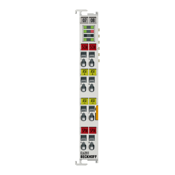
Installation LEDs and connection Fig. 36: EL6201 LEDs LEDs Color Meaning green These LEDs indicate the terminal's operating state: State of the EtherCAT State Machine [} 20]: INIT = initialization of the terminal flashing State of the EtherCAT State Machine: PREOP = function for mailbox... -
Page 37: Fig. 9 El6201
Installation Connection of the AS interface Fig. 37: Connection of EL6201 AS-i master Terminal con- Name tact 1 and 5 Setting of the configuration mode by briefly bridging contacts 1 and 5 2 and 6 ASi+ ASi+ connection (brown). Both terminal points identified with ASi+ are connected internally. -
Page 38: Fig. 38 Connection As-I Potential Supply Terminal El9520
Both terminal points identified with ASi- are connected internally. not used Uin- Negative voltage input 24 V..35 V ASi+ Connection AS-i+ Both terminal points identified with ASi+ are connected internally. ASi- Connection AS-i- Both terminal points identified with ASi- are connected internally. not used Version: 2.2 EL6201... - Page 39 Installation Wiring of the AS interface Fig. 39: Wiring diagram (example) for EL6201 AS-i master: connection to EL9520 (left), connection to AS-i power supply unit (right) Since the user data are modulated on the power supply line with the AS-Interface, a special AS-i power supply unit (30.5 V...
-
Page 40: Commissioning
• "offline": The configuration can be customized by adding and positioning individual components. These can be selected from a directory and configured. ◦ The procedure for offline mode can be found under http://infosys.beckhoff.com: TwinCAT 2 → TwinCAT System Manager → IO - Configuration → Adding an I/O Device •... - Page 41 • Linked via the X001 port (RJ-45): EK1100 EtherCAT Coupler • Connected to the EK1100 EtherCAT coupler on the right (E-bus): EL2008 (8-channel digital output terminal 24 V DC; 0.5 A) • (Optional via X000: a link to an external PC for the user interface) EL6201 Version: 2.2...
- Page 42 The starting point is the TwinCAT System Manager. After successful installation of the TwinCAT system on the PC to be used for development, the TwinCAT 2 System Manager displays the following user interface after startup: Fig. 42: Initial TwinCAT 2 user interface Version: 2.2 EL6201...
- Page 43 Fig. 44: Specify the PLC for access by the TwinCAT System Manager: selection of the target system Once the target system has been entered, it is available for selection as follows (a password may have to be entered): EL6201 Version: 2.2...
- Page 44 Confirm the message "Find new boxes", in order to determine the terminals connected to the devices. "Free Run" enables manipulation of input and output values in "Config mode" and should also be acknowledged. Based on the sample configuration [} 41] described at the beginning of this section, the result is as follows: Version: 2.2 EL6201...
- Page 45 TwinCAT PLC Control is the development environment for the creation of the controller in different program environments: TwinCAT PLC Control supports all languages described in IEC 61131-3. There are two text- based languages and three graphical languages. • Text-based languages ◦ Instruction List (IL) ◦ Structured Text (ST) EL6201 Version: 2.2...
- Page 46 The following section refers to Structured Text (ST). After starting TwinCAT PLC Control, the following user interface is shown for an initial project: Fig. 49: TwinCAT PLC Control after startup Sample variables and a sample program have been created and stored under the name "PLC_example.pro": Version: 2.2 EL6201...
- Page 47 Manager has been notified, the warning no longer appears. First, integrate the TwinCAT PLC Control project in the System Manager via the context menu of the PLC configuration; right-click and select "Append PLC Project…": Fig. 51: Appending the TwinCAT PLC Control project EL6201 Version: 2.2...
- Page 48 "PLC_example" and via "Modify Link..." "Standard": Fig. 53: Creating the links between PLC variables and process objects In the window that opens, the process object for the variable “bEL1004_Ch4” of type BOOL can be selected from the PLC configuration tree: Version: 2.2 EL6201...
- Page 49 The links can also be checked by selecting a "Goto Link Variable” from the context menu of a variable. The object opposite, in this case the PDO, is automatically selected: EL6201 Version: 2.2...
- Page 50 The PLC system can then be started as described below. Starting the controller Starting from a remote system, the PLC control has to be linked with the Embedded PC over Ethernet via "Online" → “Choose Run-Time System…": Version: 2.2 EL6201...
- Page 51 This results in the message "No program on the controller! Should the new program be loaded?", which should be acknowledged with "Yes". The runtime environment is ready for the program start: EL6201 Version: 2.2...
- Page 52 (cf. "TwinCAT System Manager" of TwinCAT 2) for communication with the electromechanical components. After successful installation of the TwinCAT system on the PC to be used for development, TwinCAT 3 (shell) displays the following user interface after startup: Version: 2.2 EL6201...
- Page 53 First create a new project via (or under "File"→“New"→ "Project…"). In the following dialog make the corresponding entries as required (as shown in the diagram): Fig. 60: Create new TwinCAT project The new project is then available in the project folder explorer: EL6201 Version: 2.2...
- Page 54 If the intention is to address the TwinCAT runtime environment installed on a PLC as development environment remotely from another system, the target system must be made known first. Via the symbol in the menu bar: expand the pull-down menu: and open the following window: Fig. 62: Selection dialog: Choose the target system Version: 2.2 EL6201...
- Page 55 The TwinCAT System Manager may first have to be set to "Config mode" via or via the menu "TwinCAT" → "Restart TwinCAT (Config mode)". Fig. 64: Select "Scan" Confirm the warning message, which follows, and select "EtherCAT" in the dialog: EL6201 Version: 2.2...
- Page 56 The whole process consists of two stages, which may be performed separately (first determine the devices, then determine the connected elements such as boxes, terminals, etc.). A scan can also be initiated by selecting "Device ..." from the context menu, which then reads the elements present in the configuration below: Version: 2.2 EL6201...
- Page 57 The following section refers to Structured Text (ST). In order to create a programming environment, a PLC subproject is added to the project sample via the context menu of "PLC" in the project folder explorer by selecting "Add New Item….": EL6201 Version: 2.2...
- Page 58 Fig. 69: Specifying the name and directory for the PLC programming environment The "Main" program, which already exists by selecting "Standard PLC project", can be opened by double- clicking on "PLC_example_project" in "POUs”. The following user interface is shown for an initial project: Version: 2.2 EL6201...
- Page 59 Commissioning Fig. 70: Initial "Main" program of the standard PLC project To continue, sample variables and a sample program have now been created: EL6201 Version: 2.2...
- Page 60 "Assignments" in the project folder explorer: Assigning variables Via the menu of an instance - variables in the "PLC” context, use the "Modify Link…" option to open a window for selecting a suitable process object (PDO) for linking: Version: 2.2 EL6201...
- Page 61 4 of the EL1004 terminal is selected for linking. In contrast, the checkbox "All types" must be ticked for creating the link for the output variables, in order to allocate a set of eight separate output bits to a byte variable. The following diagram shows the whole process: EL6201 Version: 2.2...
- Page 62 PDO, it is possible to allocate this a set of bit-standardised variables (type "BOOL"). Here, too, a "Goto Link Variable” from the context menu of a PDO can be executed in the other direction, so that the respective PLC instance can then be selected. Version: 2.2 EL6201...
- Page 63 Fig. 77: TwinCAT development environment (VS shell): logged-in, after program startup The two operator control elements for stopping and logout result in the required action (accordingly also for stop "Shift + F5", or both actions can be selected via the PLC menu). EL6201 Version: 2.2...
-
Page 64: Twincat 2
5.2.1 Installation of the TwinCAT real-time driver In order to assign real-time capability to a standard Ethernet port of an IPC controller, the Beckhoff real-time driver has to be installed on this port under Windows. This can be done in several ways. One option is described here. - Page 65 Alternatively an EtherCAT-device can be inserted first of all as described in chapter Offline configuration creation, section “Creating the EtherCAT device” [} 75] in order to view the compatible ethernet ports via its EtherCAT properties (tab „Adapter“, button „Compatible Devices…“): EL6201 Version: 2.2...
- Page 66 After the installation the driver appears activated in the Windows overview for the network interface (Windows Start → System Properties → Network) Fig. 82: Windows properties of the network interface A correct setting of the driver could be: Version: 2.2 EL6201...
- Page 67 Commissioning Fig. 83: Exemplary correct driver setting for the Ethernet port Other possible settings have to be avoided: EL6201 Version: 2.2...
- Page 68 Commissioning Fig. 84: Incorrect driver settings for the Ethernet port Version: 2.2 EL6201...
- Page 69 DHCP. In this way the delay associated with the DHCP client for the Ethernet port assigning itself a default IP address in the absence of a DHCP server is avoided. A suitable address space is 192.168.x.x, for example. Fig. 85: TCP/IP setting for the Ethernet port EL6201 Version: 2.2...
-
Page 70: Notes Regarding Esi Device Description
The files are read (once) when a new System Manager window is opened, if they have changed since the last time the System Manager window was opened. A TwinCAT installation includes the set of Beckhoff ESI files that was current at the time when the TwinCAT build was created. - Page 71 1018 in the configuration. This is also stated by the Beckhoff compatibility rule. Refer in particular to the chapter ‘General notes on the use of Beckhoff EtherCAT IO components’ and for manual configuration to the chapter ‘Offline configuration creation’ [} 75].
- Page 72 Faulty ESI file If an ESI file is faulty and the System Manager is unable to read it, the System Manager brings up an information window. Fig. 91: Information window for faulty ESI file (left: TwinCAT 2; right: TwinCAT 3) Version: 2.2 EL6201...
- Page 73 Commissioning Reasons may include: • Structure of the *.xml does not correspond to the associated *.xsd file → check your schematics • Contents cannot be translated into a device description → contact the file manufacturer EL6201 Version: 2.2...
-
Page 74: Twincat Esi Updater
Commissioning 5.2.3 TwinCAT ESI Updater For TwinCAT 2.11 and higher, the System Manager can search for current Beckhoff ESI files automatically, if an online connection is available: Fig. 92: Using the ESI Updater (>= TwinCAT 2.11) The call up takes place under: “Options” → "Update EtherCAT Device Descriptions"... -
Page 75: Offline Configuration Creation
EL6601/EL6614 terminal select “EtherCAT Automation Protocol via EL6601”. Fig. 95: Selecting the EtherCAT connection (TwinCAT 2.11, TwinCAT 3) Then assign a real Ethernet port to this virtual device in the runtime system. Fig. 96: Selecting the Ethernet port EL6201 Version: 2.2... - Page 76 Fig. “Selection dialog for new EtherCAT device”. If the preceding device has several free ports (e.g. EK1122 or EK1100), the required port can be selected on the right-hand side (A). Overview of physical layer • “Ethernet”: cable-based 100BASE-TX: EK couplers, EP boxes, devices with RJ45/M8/M12 connector Version: 2.2 EL6201...
- Page 77 (i.e. highest) revision and therefore the latest state of production is displayed in the selection dialog for Beckhoff devices. To show all device revisions available in the system as ESI descriptions tick the “Show Hidden Devices” check box, see Fig. “Display of previous revisions”.
- Page 78 If current ESI descriptions are available in the TwinCAT system, the last revision offered in the selection dialog matches the Beckhoff state of production. It is recommended to use the last device revision when creating a new configuration, if current Beckhoff devices are used in the real application. Older revisions should only be used if older devices from stock are to be used in the application.
- Page 79 Commissioning Fig. 103: EtherCAT terminal in the TwinCAT tree (left: TwinCAT 2; right: TwinCAT 3) EL6201 Version: 2.2...
-
Page 80: Online Configuration Creation
Fig. 105: Scan Devices (left: TwinCAT 2; right: TwinCAT 3) This scan mode attempts to find not only EtherCAT devices (or Ethernet ports that are usable as such), but also NOVRAM, fieldbus cards, SMB etc. However, not all devices can be found automatically. Version: 2.2 EL6201... - Page 81 [} 85] with the defined initial configura- tion.Background: since Beckhoff occasionally increases the revision version of the deliv- ered products for product maintenance reasons, a configuration can be created by such a scan which (with an identical machine construction) is identical according to the device list;...
- Page 82 Likewise, A might create spare parts stores worldwide for the coming series-produced machines with EL2521-0025-1018 terminals. After some time Beckhoff extends the EL2521-0025 by a new feature C. Therefore the FW is changed, outwardly recognizable by a higher FW version and a new revision -1019. Nevertheless the new device naturally supports functions and interfaces of the predecessor version(s);...
- Page 83 Fig. 115: Displaying of “Free Run” and “Config Mode” toggling right below in the status bar Fig. 116: TwinCAT can also be switched to this state by using a button (left: TwinCAT 2; right: TwinCAT 3) The EtherCAT system should then be in a functional cyclic state, as shown in Fig. “Online display example”. EL6201 Version: 2.2...
- Page 84 The connections and devices should be checked in a targeted manner, e.g. via the emergency scan. Then re-run the scan. Fig. 118: Faulty identification In the System Manager such devices may be set up as EK0000 or unknown devices. Operation is not possible or meaningful. Version: 2.2 EL6201...
- Page 85 A ‘ChangeTo’ or ‘Copy’ should only be Attention carried out with care, taking into consideration the Beckhoff IO compatibility rule (see above). The device configuration is then replaced by the revision found; this can affect the supported process data and functions.
- Page 86 If current ESI descriptions are available in the TwinCAT system, the last revision offered in the selection dialog matches the Beckhoff state of production. It is recommended to use the last device revision when creating a new configuration, if current Beckhoff devices are used in the real application. Older revisions should only be used if older devices from stock are to be used in the application.
- Page 87 This function is preferably to be used on AX5000 devices. If called, the System Manager suggests the devices that it finds in the associated sub-folder; in the case of the AX5000, for example, in \TwinCAT\IO \EtherCAT\Beckhoff AX5xxx. Change to Alternative Type The TwinCAT System Manager offers a function for the exchange of a device: Change to Alternative Type Fig. 124: TwinCAT 2 Dialog Change to Alternative Type...
-
Page 88: Ethercat Subscriber Configuration
Comment Here you can add a comment (e.g. regarding the system). Disabled Here you can deactivate the EtherCAT device. Create symbols Access to this EtherCAT slave via ADS is only available if this control box is activated. Version: 2.2 EL6201... - Page 89 CANopen process data objects (Process Data Objects, PDOs). The user can select a PDO via PDO assignment and modify the content of the individual PDO via this dialog, if the EtherCAT slave supports this function. EL6201 Version: 2.2...
-
Page 90: Fig. 128 "Process Data" Tab
For Beckhoff EtherCAT EL, ES, EM, EJ and EP slaves the following applies in general: • The input/output process data supported by the device are defined by the manufacturer in the ESI/XML description. -
Page 91: Fig. 129 Configuring The Process Data
(CoE) or Servo drive over EtherCAT protocol. This tab indicates which download requests are sent to the mailbox during startup. It is also possible to add new mailbox requests to the list display. The download requests are sent to the slave in the same order as they are shown in the list. EL6201 Version: 2.2... -
Page 92: Fig. 130 „Startup" Tab
(CoE) protocol. This dialog lists the content of the object list of the slave (SDO upload) and enables the user to modify the content of an object from this list. Details for the objects of the individual EtherCAT devices can be found in the device-specific object descriptions. Version: 2.2 EL6201... -
Page 93: Fig. 131 "Coe - Online" Tab
The object can be read, and data can be written to the object (read/write) The object can be read, but no data can be written to the object (read only) An additional P identifies the object as a process data object. Value Value of the object EL6201 Version: 2.2... -
Page 94: Fig. 132 Dialog "Advanced Settings
Offline - via EDS File If this option button is selected, the list of the objects included in the object list is read from an EDS file provided by the user. Version: 2.2 EL6201... -
Page 95: Fig. 133 „Online" Tab
Indicates the current state of the EtherCAT device. Requested State Indicates the state requested for the EtherCAT device. DLL Status Indicates the DLL status (data link layer status) of the individual ports of the EtherCAT slave. The DLL status can have four different states: EL6201 Version: 2.2... -
Page 96: Fig. 134 "Dc" Tab (Distributed Clocks)
• DC-Synchron Advanced Settings… Advanced settings for readjustment of the real time determinant TwinCAT- clock Detailed information to Distributed Clocks are specified on http://infosys.beckhoff.com: Fieldbus Components → EtherCAT Terminals → EtherCAT System documentation → EtherCAT basics → Distributed Clocks 5.2.7.1... - Page 97 The required commands to be sent to the device can be viewed in the Startup [} 91] tab. PDO Configuration If this check box is selected, the configuration of the respective PDOs (as shown in the PDO list and the PDO Content display) is downloaded to the EtherCAT slave. EL6201 Version: 2.2...
-
Page 98: General Notes - Ethercat Slave Application
Information variables for the EtherCAT Master that are updated acyclically. This means that it is possible that in any particular cycle they do not represent the latest possible status. It is therefore useful to read such variables through ADS. Version: 2.2 EL6201... -
Page 99: Fig. 136 Basic Ethercat Slave Diagnosis In The Plc
Fig. “Basic EtherCAT Slave Diagnosis in the PLC” shows an example of an implementation of basic EtherCAT Slave Diagnosis. A Beckhoff EL3102 (2-channel analogue input terminal) is used here, as it offers both the communication diagnosis typical of a slave and the functional diagnosis that is specific to a channel. - Page 100 The CoE parameter directory (CanOpen-over-EtherCAT) is used to manage the set values for the slave concerned. Changes may, in some circumstances, have to be made here when commissioning a relatively complex EtherCAT Slave. It can be accessed through the TwinCAT System Manager, see Fig. “EL3102, CoE directory”: Version: 2.2 EL6201...
-
Page 101: Fig. 137 El3102, Coe Directory
Commissioning interfaces are being introduced as part of an ongoing process for EL/EP EtherCAT devices. These are available in TwinCAT System Managers from TwinCAT 2.11R2 and above. They are integrated into the System Manager through appropriately extended ESI configuration files. EL6201 Version: 2.2... -
Page 102: Fig. 138 Example Of Commissioning Aid For A El3204
The target state wanted by the user, and which is brought about automatically at start-up by TwinCAT, can be set in the System Manager. As soon as TwinCAT reaches the status RUN, the TwinCAT EtherCAT Master will approach the target states. Version: 2.2 EL6201... -
Page 103: Fig. 139 Default Behaviour Of The System Manager
Fig. 139: Default behaviour of the System Manager In addition, the target state of any particular Slave can be set in the "Advanced Settings" dialogue; the standard setting is again OP. Fig. 140: Default target state in the Slave EL6201 Version: 2.2... -
Page 104: Fig. 141 Plc Function Blocks
The pre-calculated theoretical maximum E-Bus current is displayed in the TwinCAT System Manager as a column value. A shortfall is marked by a negative total amount and an exclamation mark; a power feed terminal is to be placed before such a position. Version: 2.2 EL6201... -
Page 105: Fig. 142 Illegally Exceeding The E-Bus Current
Fig. 143: Warning message for exceeding E-Bus current Caution! Malfunction possible! The same ground potential must be used for the E-Bus supply of all EtherCAT terminals in a terminal block! Attention EL6201 Version: 2.2... -
Page 106: Functionality Of The As-I Master
• Protected mode: All detected and currently projected slaves are activated, if the I/O ID and ID code of the detected slaves match the currently projected data. • Configuration mode: All detected slaves are activated by the master. Normal operation Data exchange phase Cyclic data exchange between the AS-i master and the activated slaves. Version: 2.2 EL6201... -
Page 107: Lists
7), as well as 0x8pp0:23 [} 130] (bit 7) and 0x8pp0:28 [} 130] (bit 7). Automatic addressing is possible, if I/O ID and ID code verification is enabled for all AS-i slaves listed in the LPS, and if precisely one currently projected AS-i slave is missing. EL6201 Version: 2.2... -
Page 108: Operating Phases
LAS and the LDS, and its inputs are set to the default value 0 . Once a data cycle has been completed with all activated AS-i slaves, the AS-i master enters the management phase. Version: 2.2 EL6201... -
Page 109: Address Assignment Of The As-I Slaves
The following examples initially illustrate manual addressing and integration of a digital AS-i slave in the TwinCAT system. For automatic addressing the EL6201 is commissioned with two digital and one analog AS-i slave, for example. The EL6201 is commissioned with the following configuration: •... - Page 110 Bus Terminals! WARNING • Mount the EL6201 in the terminal network as described in the section Mounting and wiring [} 27]. Cable lengths When using the EL9520 (potential distribution terminal with filter, AS-i power 24), the maxi-...
-
Page 111: Fig. 146 Maximum Topology Extent With Standard As-I Power Supply And As-I Power24 Supply
Fig. 146: Maximum topology extent with standard AS-i power supply and AS-i Power24 supply • Connect the AS-i slave and the standard 24 V power supply unit to the EL6201 according to the following wiring diagram (Fig. Wiring diagram for connecting the AS-i power supply unit and AS-i slaves with the EL6201). -
Page 112: Fig. 147 Wiring Diagram As-I Slave / El6201
Download the latest EtherCAT XML Device Description and the AS-i System Manager Extension Make sure that you download the latest XML file from the download section on the Beckhoff Note website and install it in accordance with the installation instructions. -
Page 113: Fig. 148 Configuration Tree In The Twincat System Manager
AS-i System Manager Extension is required for this. • Click on the EL6201 in the TwinCAT tree (A) and the “Settings” tab (B). Then click on "AS-i System Overview" (C) to navigate to the AS-i overview below, which shows the AS-i slaves to be addressed. -
Page 114: Fig. 149 As-I System Overview With The Slaves To Be Addressed
"0" so that you can then select an AS-i address via the "Change Address" selection field; for instance the address "1A" in the example. Fig. 150: Address assignment for the AS-i slave • The address is now shown as "Detected and activated" (blue). Version: 2.2 EL6201... -
Page 115: Fig. 151 Address Assignment For The As-I Slave Accepted
• In order to enable the AS-i data exchange, click on the grey field "ASI Data Exc INACTIVE"; the field changes to green "ASI Data Exc ACTIVE" (C). • The completed configuration is indicated by the green field “ASI Config OK”. Fig. 152: Switching to "Protected mode" and completion of project planning EL6201 Version: 2.2... -
Page 116: Fig. 153 Activating "Auto Programming Mode
• The AS-i slaves referred to above are not yet connected to the AS-i fieldbus line and have the address "0" or come straight from the factory. • Click on the EL6201 in the TwinCAT tree and the "Settings" tab (A). Then click on "AS-i master EL6201" (B) to open the screen shown below. -
Page 117: Fig. 154 No Slave Detected In The As-I System Overview
(Fig. The first slave connected is allocated address "1A"). The address is now permanently implemented in the slave. • Now connect further slaves with the AS-i fieldbus line. The slaves are allocated addresses "2A" and "3A", as shown below. Fig. 155: The first slave connected is allocated address "1A" EL6201 Version: 2.2... -
Page 118: Fig. 156 The Second Slave Connected Is Allocated Address "2A
Fig. Undefined state of a slave to be projected. Remedy: Click on the grey button "AS-i Data Exc INACTIVE", which switches to green "AS-i Data Exc ACTIVE" (see Fig.). The slaves should then show a stable state "Detected and acti- vated" (blue). Version: 2.2 EL6201... -
Page 119: Fig. 157 Undefined State Of The Slave To Be Projected
Commissioning Fig. 157: Undefined state of the slave to be projected Fig. 158: Remedy: Activating AS-i data exchange EL6201 Version: 2.2... -
Page 120: Fig. 159 The Third Connected Slave Is Allocated Address "3A"; Switching To "As-I Protected Mode"; Con- Firming The Configuration
Remedy: Check the connection between the slave and the AS-i fieldbus line. A screw-connection of the slave used in this example may be inadequate, so that the required penetration depth to the fieldbus cable is not achieved. Version: 2.2 EL6201... -
Page 121: Fig. 160 Failure Of Slave "2A", Marked Red
Fig. 160: Failure of slave "2A", marked red Changes in the AS-i slave overview The choices available for "ASI System Overview" display are shown in the screens below: Fig. 161: All slaves are shown without configuration details. Detected, projected and active slaves are marked green EL6201 Version: 2.2... -
Page 122: Fig. 162 Detected And Projected Slaves Shown Without Details
In order to show the details of the slaves, which are currently projected and active, right-click in the grey area below the slaves (or select the menu via the button "View") and select "Show slave details" in the context menu (Fig. Detected and projected slaves shown with details) Version: 2.2 EL6201... -
Page 123: Fig. 164 Profiles Of Detected And Projected Slaves Shown With Details
You can now choose between "Show Slave Info Data" and "Show Process Data" (see Fig. above) 3. Setting the parameters and process data CoE parameters If the default CoE parameters are to be changed, they must be saved for each channel in the CoE. EL6201 Version: 2.2... -
Page 124: Further Notes On Commissioning
The slave properties show the slave profile and the diagnostic data. Depending on the slave profile, further options are available, such as AS-i string parameters or string parameters for serial slaves. In addition, parameters can be set and the project planning implemented (manual project planning only in Advanced mode). Version: 2.2 EL6201... -
Page 125: Fig. 167 Left Part Of The Settings Tab
Fig. 168: AS-i master view The AS-i master view shows the configurable system status values. It also shows the firmware version and the extension (plug-in) version, which must be quoted with any support requests. EL6201 Version: 2.2... -
Page 126: Fig. 169 Option Menu "Project All Detected Slaves
(automatic start in protected mode). Fig. 169: Option menu "Project all detected slaves" • Extended view In addition, manual project planning options are available. For each slave the required profile can be specified manually via the Properties window Version: 2.2 EL6201... -
Page 127: Fig. 170 Manual Programming
Notes on the "Auto Programming" function If the function "Auto Programming" is used in Config mode, each new slave with address 0 is automatically assigned the next free address. Note that slaves with the profile S-6.0 can Note require several addresses. EL6201 Version: 2.2... - Page 128 Slaves of type CTT5 (S-6.0) achieve a higher velocity thanks to the use of several slave addresses. Depending on the slave, the number of slave addresses used can be set via the extended ID code. To change the extended ID code the slave address must be 0, see the figure below. Version: 2.2 EL6201...
- Page 129 - Acyclic communication via "AS-i string command" (0x2010-object). Command structure: Byte Content Increment for new command 0x02 (Write Parameter string) Slave address* Command-Length** 4 - 7 Reserved Command Example: 01 02 03* 03** 00 00 00 00 10 00 DB EL6201 Version: 2.2...
-
Page 130: Object Description And Parameterization
EtherCAT XML Device Description The display matches that of the CoE objects from the EtherCAT XML Device Description. We recommend downloading the latest XML file from the download area of the Beckhoff Note website and installing it according to installation instructions. - Page 131 0 - 15 Extended ID code 1 (A-slave or standard slave) (default 0) 4 - 6 reserved Value is taken into account when comparing set/actual configuration in protected mode Value is ignored when comparing set/actual configuration in protected mode EL6201 Version: 2.2...
- Page 132 The projected 4-bit ID codes of the AS-i slaves are located in the object 0x8pp0:21 (these objects are read-write and are saved in the Flash of the AS-i master (i.e. they are still present after power off/on)): (see following table) Version: 2.2 EL6201...
- Page 133 Flash of the AS-i master, i.e. they are still present after power off/on of the AS-i master. (see follow- ing table) Value Description 0 - 2 0 - 7 Parameter (B-slave) (default 7) 3 - 7 reserved EL6201 Version: 2.2...
-
Page 134: Command Object
7 set): addressing call If the error bit (bit 15) is not set, bits 31 to 24 contain the value 00 If the error bit (bit 15) is set, bits 31 to 24 contain an error code. (see following table) Version: 2.2 EL6201... - Page 135 0x22 Address 0 is currently assigned to another slave. In order to change the address of an AS-i slave, the EL6201 must first assign the address 0 to the slave in order to address it again afterwards from there. 0x36 A slave with the address that was specified as the new address already exists.
- Page 136 Slave is not an analog slave 0x20 Slave does not support slave profile 0x40 String transfer is already active 0x80 Data exchange is not active 0x08 Command is not supported 32 - 63 reserved 64 - xxxx String data 2047 Version: 2.2 EL6201...
-
Page 137: Input Data
10F3:05 Flags reserved UINT16 0x0000 (0 10F3:06 - Diagnosis Message reserved OCTET- 001 - 016 STRING[20] Index 10F8 Actual Time Stamp Index (hex) Name Meaning Data type Flags Default 10F8:0 Actual Time Stamp Time stamp UINT64 EL6201 Version: 2.2... -
Page 138: Diagnostic Data
Index App0 ASI Diag Data Slave (for 00 ≤ pp ≤ 1F; slave 0 to slave 31) Index (hex) Name Meaning Data type Flags Default App0:02 Status Register (A- General status information UINT8 0x00 (0 Slave) Last received response of a slave to the command "ReadStatus" (see table below) Version: 2.2 EL6201... - Page 139 Status Register (B- General status information UINT8 0x00 (0 Slave) Last received response of a slave to the command "ReadStatus" (see table below) Description 0 - 3 Status register of the slave (default = 0) 4 - 7 reserved EL6201 Version: 2.2...
- Page 140 Timeouts per telegram in percent UINT16 0x0000 (0 Slave) App0:12 Data-Exchange Re- This counter is incremented if the data exchange has to UINT16 0x0000 (0 peat Counter (B- be repeated (slave responded incorrectly or not all) Slave) Version: 2.2 EL6201...
-
Page 141: Asi Data
Slave 1B ... 31B Slave 1B ... 31B detected BOOLEAN 0x00 (0 Index F102 ASI LAS All slaves with which the master communicates. In protected mode, this list corresponds to the LPS, in configuration mode it corresponds to the LDS EL6201 Version: 2.2... - Page 142 F200:05 Go Configuration : activate configuration mode BOOLEAN 0x00 (0 Mode F200:06*** Toggle Power24 Activate Power24 mode BOOLEAN 0x00 (0 mode F200:07*** Toggle M4 Profile Activate M4 Profile support BOOLEAN 0x00 (0 Support ***) from firmware 02 Version: 2.2 EL6201...
- Page 143 Sensor in status OFF, but only contact 1 open Sensor according to the rules in status OFF Evaluation of not permitted! Evaluation of the safety flags, shown in the process image of EL6201 for controlling safety- relevant functions is not permitted! WARNING They are not allowed to be used for protection functions such as emergency stop, access protection, protected area monitoring, robot area monitoring, press safety valves etc.!
- Page 144 BOOLEAN 0x00 (0 F902:02 ... Slave 1A ... 31A Slave 1A ... 31A is a safety slave BOOLEAN 0x00 (0 F902:21 ... Slave 1B ... 31B Slave 1B ... 31B is a safety slave BOOLEAN 0x00 (0 Version: 2.2 EL6201...
-
Page 145: Object Description - Standard Objects
Index (hex) Name Meaning Data type Flags Default 1008:0 Device name Device name of the EtherCAT slave STRING EL6201 Index 1009 Hardware version Index (hex) Name Meaning Data type Flags Default 1009:0 Hardware version Hardware version of the EtherCAT slave... - Page 146 7. PDO Mapping entry (object 0x7030 (ASI Analog Out- UINT32 0x7030:07, 16 puts Slave 3 ), entry 0x07 (State Ch.4 (A-Slave))) 1603:08 SubIndex 008 8. PDO Mapping entry (object 0x7030 (ASI Analog Out- UINT32 0x7030:08, 16 puts Slave 3 ), entry 0x08 (Value Ch.4 (A-Slave))) Version: 2.2 EL6201...
- Page 147 7. PDO Mapping entry (object 0x7060 (ASI Analog Out- UINT32 0x7060:07, 16 puts Slave 6 ), entry 0x07 (State Ch.4 (A-Slave))) 1606:08 SubIndex 008 8. PDO Mapping entry (object 0x7060 (ASI Analog Out- UINT32 0x7060:08, 16 puts Slave 6 ), entry 0x08 (Value Ch.4 (A-Slave))) EL6201 Version: 2.2...
- Page 148 7. PDO Mapping entry (object 0x7090 (ASI Analog Out- UINT32 0x7090:07, 16 puts Slave 9 ), entry 0x07 (State Ch.4 (A-Slave))) 1609:08 SubIndex 008 8. PDO Mapping entry (object 0x7090 (ASI Analog Out- UINT32 0x7090:08, 16 puts Slave 9 ), entry 0x08 (Value Ch.4 (A-Slave))) Version: 2.2 EL6201...
- Page 149 7. PDO Mapping entry (object 0x70C0 (ASI Analog Out- UINT32 0x70C0:07, puts Slave 12 ), entry 0x07 (State Ch.4 (A-Slave))) 160C:08 SubIndex 008 8. PDO Mapping entry (object 0x70C0 (ASI Analog Out- UINT32 0x70C0:08, puts Slave 12 ), entry 0x08 (Value Ch.4 (A-Slave))) EL6201 Version: 2.2...
- Page 150 7. PDO Mapping entry (object 0x70F0 (ASI Analog Out- UINT32 0x70F0:07, 16 puts Slave 15 ), entry 0x07 (State Ch.4 (A-Slave))) 160F:08 SubIndex 008 8. PDO Mapping entry (object 0x70F0 (ASI Analog Out- UINT32 0x70F0:08, 16 puts Slave 15 ), entry 0x08 (Value Ch.4 (A-Slave))) Version: 2.2 EL6201...
- Page 151 7. PDO Mapping entry (object 0x7120 (ASI Analog Out- UINT32 0x7120:07, 16 puts Slave 18 ), entry 0x07 (State Ch.4 (A-Slave))) 1612:08 SubIndex 008 8. PDO Mapping entry (object 0x7120 (ASI Analog Out- UINT32 0x7120:08, 16 puts Slave 18 ), entry 0x08 (Value Ch.4 (A-Slave))) EL6201 Version: 2.2...
- Page 152 7. PDO Mapping entry (object 0x7150 (ASI Analog Out- UINT32 0x7150:07, 16 puts Slave 21 ), entry 0x07 (State Ch.4 (A-Slave))) 1615:08 SubIndex 008 8. PDO Mapping entry (object 0x7150 (ASI Analog Out- UINT32 0x7150:08, 16 puts Slave 21 ), entry 0x08 (Value Ch.4 (A-Slave))) Version: 2.2 EL6201...
- Page 153 7. PDO Mapping entry (object 0x7180 (ASI Analog Out- UINT32 0x7180:07, 16 puts Slave 24 ), entry 0x07 (State Ch.4 (A-Slave))) 1618:08 SubIndex 008 8. PDO Mapping entry (object 0x7180 (ASI Analog Out- UINT32 0x7180:08, 16 puts Slave 24 ), entry 0x08 (Value Ch.4 (A-Slave))) EL6201 Version: 2.2...
- Page 154 7. PDO Mapping entry (object 0x71B0 (ASI Analog Out- UINT32 0x71B0:07, 16 puts Slave 27 ), entry 0x07 (State Ch.4 (A-Slave))) 161B:08 SubIndex 008 8. PDO Mapping entry (object 0x71B0 (ASI Analog Out- UINT32 0x71B0:08, 16 puts Slave 27 ), entry 0x08 (Value Ch.4 (A-Slave))) Version: 2.2 EL6201...
- Page 155 7. PDO Mapping entry (object 0x71E0 (ASI Analog Out- UINT32 0x71E0:07, 16 puts Slave 30 ), entry 0x07 (State Ch.4 (A-Slave))) 161E:08 SubIndex 008 8. PDO Mapping entry (object 0x71E0 (ASI Analog Out- UINT32 0x71E0:08, 16 puts Slave 30 ), entry 0x08 (Value Ch.4 (A-Slave))) EL6201 Version: 2.2...
- Page 156 14. PDO Mapping entry (object 0xF700 (ASI Digital Out- UINT32 0xF700:0E, 1 puts), entry 0x0E (Slave 2 Outputs__Slave 2B, DO1)) 1640:0F SubIndex 015 15. PDO Mapping entry (object 0xF700 (ASI Digital Out- UINT32 0xF700:0F, 1 puts), entry 0x0F (Slave 2 Outputs__Slave 2B, DO2)) Version: 2.2 EL6201...
- Page 157 30. PDO Mapping entry (object 0xF700 (ASI Digital Out- UINT32 0xF700:1E, 1 puts), entry 0x1E (Slave 4 Outputs__Slave 4B, DO1)) 1640:1F SubIndex 031 31. PDO Mapping entry (object 0xF700 (ASI Digital Out- UINT32 0xF700:1F, 1 puts), entry 0x1F (Slave 4 Outputs__Slave 4B, DO2)) EL6201 Version: 2.2...
- Page 158 46. PDO Mapping entry (object 0xF700 (ASI Digital Out- UINT32 0xF700:2E, 1 puts), entry 0x2E (Slave 6 Outputs__Slave 6B, DO1)) 1640:2F SubIndex 047 47. PDO Mapping entry (object 0xF700 (ASI Digital Out- UINT32 0xF700:2F, 1 puts), entry 0x2F (Slave 6 Outputs__Slave 6B, DO2)) Version: 2.2 EL6201...
- Page 159 62. PDO Mapping entry (object 0xF700 (ASI Digital Out- UINT32 0xF700:3E, 1 puts), entry 0x3E (Slave 8 Outputs__Slave 8B, DO1)) 1640:3F SubIndex 063 63. PDO Mapping entry (object 0xF700 (ASI Digital Out- UINT32 0xF700:3F, 1 puts), entry 0x3F (Slave 8 Outputs__Slave 8B, DO2)) EL6201 Version: 2.2...
- Page 160 78. PDO Mapping entry (object 0xF700 (ASI Digital Out- UINT32 0xF700:4E, 1 puts), entry 0x4E (Slave 10 Outputs__Slave 10B, DO1)) 1640:4F SubIndex 079 79. PDO Mapping entry (object 0xF700 (ASI Digital Out- UINT32 0xF700:4F, 1 puts), entry 0x4F (Slave 10 Outputs__Slave 10B, DO2)) Version: 2.2 EL6201...
- Page 161 94. PDO Mapping entry (object 0xF700 (ASI Digital Out- UINT32 0xF700:5E, 1 puts), entry 0x5E (Slave 12 Outputs__Slave 12B, DO1)) 1640:5F SubIndex 095 95. PDO Mapping entry (object 0xF700 (ASI Digital Out- UINT32 0xF700:5F, 1 puts), entry 0x5F (Slave 12 Outputs__Slave 12B, DO2)) EL6201 Version: 2.2...
- Page 162 110. PDO Mapping entry (object 0xF700 (ASI Digital Out- UINT32 0xF700:6E, 1 puts), entry 0x6E (Slave 14 Outputs__Slave 14B, DO1)) 1640:6F SubIndex 111 111. PDO Mapping entry (object 0xF700 (ASI Digital Out- UINT32 0xF700:6F, 1 puts), entry 0x6F (Slave 14 Outputs__Slave 14B, DO2)) Version: 2.2 EL6201...
- Page 163 126. PDO Mapping entry (object 0xF700 (ASI Digital Out- UINT32 0xF700:7E, 1 puts), entry 0x7E (Slave 16 Outputs__Slave 16B, DO1)) 1640:7F SubIndex 127 127. PDO Mapping entry (object 0xF700 (ASI Digital Out- UINT32 0xF700:7F, 1 puts), entry 0x7F (Slave 16 Outputs__Slave 16B, DO2)) EL6201 Version: 2.2...
- Page 164 142. PDO Mapping entry (object 0xF700 (ASI Digital Out- UINT32 0xF700:8E, 1 puts), entry 0x8E (Slave 18 Outputs__Slave 18B, DO1)) 1640:8F SubIndex 143 143. PDO Mapping entry (object 0xF700 (ASI Digital Out- UINT32 0xF700:8F, 1 puts), entry 0x8F (Slave 18 Outputs__Slave 18B, DO2)) Version: 2.2 EL6201...
- Page 165 158. PDO Mapping entry (object 0xF700 (ASI Digital Out- UINT32 0xF700:9E, 1 puts), entry 0x9E (Slave 20 Outputs__Slave 20B, DO1)) 1640:9F SubIndex 159 159. PDO Mapping entry (object 0xF700 (ASI Digital Out- UINT32 0xF700:9F, 1 puts), entry 0x9F (Slave 20 Outputs__Slave 20B, DO2)) EL6201 Version: 2.2...
- Page 166 174. PDO Mapping entry (object 0xF700 (ASI Digital Out- UINT32 0xF700:AE, 1 puts), entry 0xAE (Slave 22 Outputs__Slave 22B, DO1)) 1640:AF SubIndex 175 175. PDO Mapping entry (object 0xF700 (ASI Digital Out- UINT32 0xF700:AF, 1 puts), entry 0xAF (Slave 22 Outputs__Slave 22B, DO2)) Version: 2.2 EL6201...
- Page 167 190. PDO Mapping entry (object 0xF700 (ASI Digital Out- UINT32 0xF700:BE, 1 puts), entry 0xBE (Slave 24 Outputs__Slave 24B, DO1)) 1640:BF SubIndex 191 191. PDO Mapping entry (object 0xF700 (ASI Digital Out- UINT32 0xF700:BF, 1 puts), entry 0xBF (Slave 24 Outputs__Slave 24B, DO2)) EL6201 Version: 2.2...
- Page 168 206. PDO Mapping entry (object 0xF700 (ASI Digital Out- UINT32 0xF700:CE, 1 puts), entry 0xCE (Slave 26 Outputs__Slave 26B, DO1)) 1640:CF SubIndex 207 207. PDO Mapping entry (object 0xF700 (ASI Digital Out- UINT32 0xF700:CF, 1 puts), entry 0xCF (Slave 26 Outputs__Slave 26B, DO2)) Version: 2.2 EL6201...
- Page 169 222. PDO Mapping entry (object 0xF700 (ASI Digital Out- UINT32 0xF700:DE, 1 puts), entry 0xDE (Slave 28 Outputs__Slave 28B, DO1)) 1640:DF SubIndex 223 223. PDO Mapping entry (object 0xF700 (ASI Digital Out- UINT32 0xF700:DF, 1 puts), entry 0xDF (Slave 28 Outputs__Slave 28B, DO2)) EL6201 Version: 2.2...
- Page 170 247. PDO Mapping entry (object 0xF700 (ASI Digital Out- UINT32 0xF700:F7, 1 puts), entry 0xF7 (Slave 31 Outputs__Slave 31B, DO2)) 1640:F8 SubIndex 248 248. PDO Mapping entry (object 0xF700 (ASI Digital Out- UINT32 0xF700:F8, 1 puts), entry 0xF8 (Slave 31 Outputs__Slave 31B, DO3)) Version: 2.2 EL6201...
- Page 171 7. PDO Mapping entry (object 0x6020 (ASI Analog Inputs UINT32 0x6020:07, 16 Slave 2 ), entry 0x07 (State Ch.4 (A-Slave))) 1A02:08 SubIndex 008 8. PDO Mapping entry (object 0x6020 (ASI Analog Inputs UINT32 0x6020:08, 16 Slave 2 ), entry 0x08 (Value Ch.4 (A-Slave))) EL6201 Version: 2.2...
- Page 172 7. PDO Mapping entry (object 0x6050 (ASI Analog Inputs UINT32 0x6050:07, 16 Slave 5 ), entry 0x07 (State Ch.4 (A-Slave))) 1A05:08 SubIndex 008 8. PDO Mapping entry (object 0x6050 (ASI Analog Inputs UINT32 0x6050:08, 16 Slave 5 ), entry 0x08 (Value Ch.4 (A-Slave))) Version: 2.2 EL6201...
- Page 173 7. PDO Mapping entry (object 0x6080 (ASI Analog Inputs UINT32 0x6080:07, 16 Slave 8 ), entry 0x07 (State Ch.4 (A-Slave))) 1A08:08 SubIndex 008 8. PDO Mapping entry (object 0x6080 (ASI Analog Inputs UINT32 0x6080:08, 16 Slave 8 ), entry 0x08 (Value Ch.4 (A-Slave))) EL6201 Version: 2.2...
- Page 174 7. PDO Mapping entry (object 0x60B0 (ASI Analog In- UINT32 0x60B0:07, 16 puts Slave 11 ), entry 0x07 (State Ch.4 (A-Slave))) 1A0B:08 SubIndex 008 8. PDO Mapping entry (object 0x60B0 (ASI Analog In- UINT32 0x60B0:08, 16 puts Slave 11 ), entry 0x08 (Value Ch.4 (A-Slave))) Version: 2.2 EL6201...
- Page 175 7. PDO Mapping entry (object 0x60E0 (ASI Analog In- UINT32 0x60E0:07, 16 puts Slave 14 ), entry 0x07 (State Ch.4 (A-Slave))) 1A0E:08 SubIndex 008 8. PDO Mapping entry (object 0x60E0 (ASI Analog In- UINT32 0x60E0:08, 16 puts Slave 14 ), entry 0x08 (Value Ch.4 (A-Slave))) EL6201 Version: 2.2...
- Page 176 7. PDO Mapping entry (object 0x6110 (ASI Analog Inputs UINT32 0x6110:07, 16 Slave 17 ), entry 0x07 (State Ch.4 (A-Slave))) 1A11:08 SubIndex 008 8. PDO Mapping entry (object 0x6110 (ASI Analog Inputs UINT32 0x6110:08, 16 Slave 17 ), entry 0x08 (Value Ch.4 (A-Slave))) Version: 2.2 EL6201...
- Page 177 7. PDO Mapping entry (object 0x6140 (ASI Analog Inputs UINT32 0x6140:07, 16 Slave 20 ), entry 0x07 (State Ch.4 (A-Slave))) 1A14:08 SubIndex 008 8. PDO Mapping entry (object 0x6140 (ASI Analog Inputs UINT32 0x6140:08, 16 Slave 20 ), entry 0x08 (Value Ch.4 (A-Slave))) EL6201 Version: 2.2...
- Page 178 7. PDO Mapping entry (object 0x6170 (ASI Analog Inputs UINT32 0x6170:07, 16 Slave 23 ), entry 0x07 (State Ch.4 (A-Slave))) 1A17:08 SubIndex 008 8. PDO Mapping entry (object 0x6170 (ASI Analog Inputs UINT32 0x6170:08, 16 Slave 23 ), entry 0x08 (Value Ch.4 (A-Slave))) Version: 2.2 EL6201...
- Page 179 7. PDO Mapping entry (object 0x61A0 (ASI Analog In- UINT32 0x61A0:07, 16 puts Slave 26 ), entry 0x07 (State Ch.4 (A-Slave))) 1A1A:08 SubIndex 008 8. PDO Mapping entry (object 0x61A0 (ASI Analog In- UINT32 0x61A0:08, 16 puts Slave 26 ), entry 0x08 (Value Ch.4 (A-Slave))) EL6201 Version: 2.2...
- Page 180 7. PDO Mapping entry (object 0x61D0 (ASI Analog In- UINT32 0x61D0:07, puts Slave 29 ), entry 0x07 (State Ch.4 (A-Slave))) 1A1D:08 SubIndex 008 8. PDO Mapping entry (object 0x61D0 (ASI Analog In- UINT32 0x61D0:08, puts Slave 29 ), entry 0x08 (Value Ch.4 (A-Slave))) Version: 2.2 EL6201...
- Page 181 7. PDO Mapping entry (object 0x61F0 (ASI Analog Inputs UINT32 0x61F0:07, 16 Slave 31 ), entry 0x07 (State Ch.4 (A-Slave))) 1A1F:08 SubIndex 008 8. PDO Mapping entry (object 0x61F0 (ASI Analog Inputs UINT32 0x61F0:08, 16 Slave 31 ), entry 0x08 (Value Ch.4 (A-Slave))) EL6201 Version: 2.2...
- Page 182 14. PDO Mapping entry (object 0xF600 (ASI Digital In- UINT32 0xF600:0E, 1 puts), entry 0x0E (Slave 2 Inputs__Slave 2B, DI1)) 1A40:0F SubIndex 015 15. PDO Mapping entry (object 0xF600 (ASI Digital In- UINT32 0xF600:0F, 1 puts), entry 0x0F (Slave 2 Inputs__Slave 2B, DI2)) Version: 2.2 EL6201...
- Page 183 30. PDO Mapping entry (object 0xF600 (ASI Digital In- UINT32 0xF600:1E, 1 puts), entry 0x1E (Slave 4 Inputs__Slave 4B, DI1)) 1A40:1F SubIndex 031 31. PDO Mapping entry (object 0xF600 (ASI Digital In- UINT32 0xF600:1F, 1 puts), entry 0x1F (Slave 4 Inputs__Slave 4B, DI2)) EL6201 Version: 2.2...
- Page 184 46. PDO Mapping entry (object 0xF600 (ASI Digital In- UINT32 0xF600:2E, 1 puts), entry 0x2E (Slave 6 Inputs__Slave 6B, DI1)) 1A40:2F SubIndex 047 47. PDO Mapping entry (object 0xF600 (ASI Digital In- UINT32 0xF600:2F, 1 puts), entry 0x2F (Slave 6 Inputs__Slave 6B, DI2)) Version: 2.2 EL6201...
- Page 185 62. PDO Mapping entry (object 0xF600 (ASI Digital In- UINT32 0xF600:3E, 1 puts), entry 0x3E (Slave 8 Inputs__Slave 8B, DI1)) 1A40:3F SubIndex 063 63. PDO Mapping entry (object 0xF600 (ASI Digital In- UINT32 0xF600:3F, 1 puts), entry 0x3F (Slave 8 Inputs__Slave 8B, DI2)) EL6201 Version: 2.2...
- Page 186 78. PDO Mapping entry (object 0xF600 (ASI Digital In- UINT32 0xF600:4E, 1 puts), entry 0x4E (Slave 10 Inputs__Slave 10B, DI1)) 1A40:4F SubIndex 079 79. PDO Mapping entry (object 0xF600 (ASI Digital In- UINT32 0xF600:4F, 1 puts), entry 0x4F (Slave 10 Inputs__Slave 10B, DI2)) Version: 2.2 EL6201...
- Page 187 94. PDO Mapping entry (object 0xF600 (ASI Digital In- UINT32 0xF600:5E, 1 puts), entry 0x5E (Slave 12 Inputs__Slave 12B, DI1)) 1A40:5F SubIndex 095 95. PDO Mapping entry (object 0xF600 (ASI Digital In- UINT32 0xF600:5F, 1 puts), entry 0x5F (Slave 12 Inputs__Slave 12B, DI2)) EL6201 Version: 2.2...
- Page 188 110. PDO Mapping entry (object 0xF600 (ASI Digital In- UINT32 0xF600:6E, 1 puts), entry 0x6E (Slave 14 Inputs__Slave 14B, DI1)) 1A40:6F SubIndex 111 111. PDO Mapping entry (object 0xF600 (ASI Digital In- UINT32 0xF600:6F, 1 puts), entry 0x6F (Slave 14 Inputs__Slave 14B, DI2)) Version: 2.2 EL6201...
- Page 189 126. PDO Mapping entry (object 0xF600 (ASI Digital In- UINT32 0xF600:7E, 1 puts), entry 0x7E (Slave 16 Inputs__Slave 16B, DI1)) 1A40:7F SubIndex 127 127. PDO Mapping entry (object 0xF600 (ASI Digital In- UINT32 0xF600:7F, 1 puts), entry 0x7F (Slave 16 Inputs__Slave 16B, DI2)) EL6201 Version: 2.2...
- Page 190 142. PDO Mapping entry (object 0xF600 (ASI Digital In- UINT32 0xF600:8E, 1 puts), entry 0x8E (Slave 18 Inputs__Slave 18B, DI1)) 1A40:8F SubIndex 143 143. PDO Mapping entry (object 0xF600 (ASI Digital In- UINT32 0xF600:8F, 1 puts), entry 0x8F (Slave 18 Inputs__Slave 18B, DI2)) Version: 2.2 EL6201...
- Page 191 158. PDO Mapping entry (object 0xF600 (ASI Digital In- UINT32 0xF600:9E, 1 puts), entry 0x9E (Slave 20 Inputs__Slave 20B, DI1)) 1A40:9F SubIndex 159 159. PDO Mapping entry (object 0xF600 (ASI Digital In- UINT32 0xF600:9F, 1 puts), entry 0x9F (Slave 20 Inputs__Slave 20B, DI2)) EL6201 Version: 2.2...
- Page 192 174. PDO Mapping entry (object 0xF600 (ASI Digital In- UINT32 0xF600:AE, 1 puts), entry 0xAE (Slave 22 Inputs__Slave 22B, DI1)) 1A40:AF SubIndex 175 175. PDO Mapping entry (object 0xF600 (ASI Digital In- UINT32 0xF600:AF, 1 puts), entry 0xAF (Slave 22 Inputs__Slave 22B, DI2)) Version: 2.2 EL6201...
- Page 193 190. PDO Mapping entry (object 0xF600 (ASI Digital In- UINT32 0xF600:BE, 1 puts), entry 0xBE (Slave 24 Inputs__Slave 24B, DI1)) 1A40:BF SubIndex 191 191. PDO Mapping entry (object 0xF600 (ASI Digital In- UINT32 0xF600:BF, 1 puts), entry 0xBF (Slave 24 Inputs__Slave 24B, DI2)) EL6201 Version: 2.2...
- Page 194 206. PDO Mapping entry (object 0xF600 (ASI Digital In- UINT32 0xF600:CE, 1 puts), entry 0xCE (Slave 26 Inputs__Slave 26B, DI1)) 1A40:CF SubIndex 207 207. PDO Mapping entry (object 0xF600 (ASI Digital In- UINT32 0xF600:CF, 1 puts), entry 0xCF (Slave 26 Inputs__Slave 26B, DI2)) Version: 2.2 EL6201...
- Page 195 222. PDO Mapping entry (object 0xF600 (ASI Digital In- UINT32 0xF600:DE, 1 puts), entry 0xDE (Slave 28 Inputs__Slave 28B, DI1)) 1A40:DF SubIndex 223 223. PDO Mapping entry (object 0xF600 (ASI Digital In- UINT32 0xF600:DF, 1 puts), entry 0xDF (Slave 28 Inputs__Slave 28B, DI2)) EL6201 Version: 2.2...
- Page 196 247. PDO Mapping entry (object 0xF600 (ASI Digital In- UINT32 0xF600:F7, 1 puts), entry 0xF7 (Slave 31 Inputs__Slave 31B, DI2)) 1A40:F8 SubIndex 248 248. PDO Mapping entry (object 0xF600 (ASI Digital In- UINT32 0xF600:F8, 1 puts), entry 0xF8 (Slave 31 Inputs__Slave 31B, DI3)) Version: 2.2 EL6201...
- Page 197 0x0D (Slave 12A)) 1A81:0E SubIndex 014 14. PDO Mapping entry (object 0xF101 (ASI LDS), entry UINT32 0xF101:0E, 1 0x0E (Slave 13A)) 1A81:0F SubIndex 015 15. PDO Mapping entry (object 0xF101 (ASI LDS), entry UINT32 0xF101:0F, 1 0x0F (Slave 14A)) EL6201 Version: 2.2...
- Page 198 0x1D (Slave 28A)) 1A81:1E SubIndex 030 30. PDO Mapping entry (object 0xF101 (ASI LDS), entry UINT32 0xF101:1E, 1 0x1E (Slave 29A)) 1A81:1F SubIndex 031 31. PDO Mapping entry (object 0xF101 (ASI LDS), entry UINT32 0xF101:1F, 1 0x1F (Slave 30A)) Version: 2.2 EL6201...
- Page 199 0x2D (Slave 13B)) 1A81:2E SubIndex 046 46. PDO Mapping entry (object 0xF101 (ASI LDS), entry UINT32 0xF101:2E, 1 0x2E (Slave 14B)) 1A81:2F SubIndex 047 47. PDO Mapping entry (object 0xF101 (ASI LDS), entry UINT32 0xF101:2F, 1 0x2F (Slave 15B)) EL6201 Version: 2.2...
- Page 200 UINT32 0xF101:3E, 1 0x3E (Slave 30B)) 1A81:3F SubIndex 063 63. PDO Mapping entry (object 0xF101 (ASI LDS), entry UINT32 0xF101:3F, 1 0x3F (Slave 31B)) 1A81:40 SubIndex 064 64. PDO Mapping entry (1 bits align) UINT32 0x0000:00, 1 Version: 2.2 EL6201...
- Page 201 0x0D (Slave 12A)) 1A82:0E SubIndex 014 14. PDO Mapping entry (object 0xF102 (ASI LAS), entry UINT32 0xF102:0E, 1 0x0E (Slave 13A)) 1A82:0F SubIndex 015 15. PDO Mapping entry (object 0xF102 (ASI LAS), entry UINT32 0xF102:0F, 1 0x0F (Slave 14A)) EL6201 Version: 2.2...
- Page 202 0x1D (Slave 28A)) 1A82:1E SubIndex 030 30. PDO Mapping entry (object 0xF102 (ASI LAS), entry UINT32 0xF102:1E, 1 0x1E (Slave 29A)) 1A82:1F SubIndex 031 31. PDO Mapping entry (object 0xF102 (ASI LAS), entry UINT32 0xF102:1F, 1 0x1F (Slave 30A)) Version: 2.2 EL6201...
- Page 203 0x2D (Slave 13B)) 1A82:2E SubIndex 046 46. PDO Mapping entry (object 0xF102 (ASI LAS), entry UINT32 0xF102:2E, 1 0x2E (Slave 14B)) 1A82:2F SubIndex 047 47. PDO Mapping entry (object 0xF102 (ASI LAS), entry UINT32 0xF102:2F, 1 0x2F (Slave 15B)) EL6201 Version: 2.2...
- Page 204 UINT32 0xF102:3E, 1 0x3E (Slave 30B)) 1A82:3F SubIndex 063 63. PDO Mapping entry (object 0xF102 (ASI LAS), entry UINT32 0xF102:3F, 1 0x3F (Slave 31B)) 1A82:40 SubIndex 064 64. PDO Mapping entry (1 bits align) UINT32 0x0000:00, 1 Version: 2.2 EL6201...
- Page 205 0x0D (Slave 12A)) 1A83:0E SubIndex 014 14. PDO Mapping entry (object 0xF103 (ASI LPS), entry UINT32 0xF103:0E, 1 0x0E (Slave 13A)) 1A83:0F SubIndex 015 15. PDO Mapping entry (object 0xF103 (ASI LPS), entry UINT32 0xF103:0F, 1 0x0F (Slave 14A)) EL6201 Version: 2.2...
- Page 206 0x1D (Slave 28A)) 1A83:1E SubIndex 030 30. PDO Mapping entry (object 0xF103 (ASI LPS), entry UINT32 0xF103:1E, 1 0x1E (Slave 29A)) 1A83:1F SubIndex 031 31. PDO Mapping entry (object 0xF103 (ASI LPS), entry UINT32 0xF103:1F, 1 0x1F (Slave 30A)) Version: 2.2 EL6201...
- Page 207 0x2D (Slave 13B)) 1A83:2E SubIndex 046 46. PDO Mapping entry (object 0xF103 (ASI LPS), entry UINT32 0xF103:2E, 1 0x2E (Slave 14B)) 1A83:2F SubIndex 047 47. PDO Mapping entry (object 0xF103 (ASI LPS), entry UINT32 0xF103:2F, 1 0x2F (Slave 15B)) EL6201 Version: 2.2...
- Page 208 Sync-Manager Type Channel 2: Mailbox Read UINT8 0x02 (2 1C00:03 SubIndex 003 Sync-Manager Type Channel 3: Process Data Write UINT8 0x03 (3 (Outputs) 1C00:04 SubIndex 004 Sync-Manager Type Channel 4: Process Data Read (In- UINT8 0x04 (4 puts) Version: 2.2 EL6201...
- Page 209 SubIndex 014 14. allocated RxPDO (contains the index of the associ- UINT16 0x0000 (0 ated RxPDO mapping object) 1C12:0F SubIndex 015 15. allocated RxPDO (contains the index of the associ- UINT16 0x0000 (0 ated RxPDO mapping object) EL6201 Version: 2.2...
- Page 210 SubIndex 033 33. allocated RxPDO (contains the index of the associ- UINT16 0x0000 (0 ated RxPDO mapping object) 1C12:22 SubIndex 034 34. allocated RxPDO (contains the index of the associ- UINT16 0x0000 (0 ated RxPDO mapping object) Version: 2.2 EL6201...
- Page 211 SubIndex 014 14. allocated TxPDO (contains the index of the associ- UINT16 0x0000 (0 ated TxPDO mapping object) 1C13:0F SubIndex 015 15. allocated TxPDO (contains the index of the associ- UINT16 0x0000 (0 ated TxPDO mapping object) EL6201 Version: 2.2...
- Page 212 SubIndex 036 36. allocated TxPDO (contains the index of the associ- UINT16 0x0000 (0 ated TxPDO mapping object) 1C13:25 SubIndex 037 37. allocated TxPDO (contains the index of the associ- UINT16 0x0000 (0 ated TxPDO mapping object) Version: 2.2 EL6201...
- Page 213 Shift too short counter Number of occasions that the interval between SYNC0 UINT16 0x0000 (0 and SYNC1 event was too short (DC mode only) 1C32:20 Sync error The synchronization was not correct in the last cycle BOOLEAN 0x00 (0 (outputs were output too late; DC mode only) EL6201 Version: 2.2...
- Page 214 Index distance of the objects of the individual channels UINT16 0x0010 (16 tance F000:02 Maximum number of Number of channels UINT16 0x0020 (32 modules Index F008 Code word Index (hex) Name Meaning Data type Flags Default F008:0 Code word reserved UINT32 0x00000000 Version: 2.2 EL6201...
- Page 215 Commissioning Index F010 Module list Index (hex) Name Meaning Data type Flags Default F010:0 Module list reserved UINT8 0x20 (32 F010:01 - SubIndex 001 - 032 reserved UINT32 0x00001838 (6200 EL6201 Version: 2.2...
-
Page 216: Appendix
Check on the Beckhoff web page whether more up-to-date documentation is available. Firmware Update EL/ES/EM/EPxxxx This section describes the device update for Beckhoff EtherCAT slaves from the EL/ES, EM, EK and EP series. A firmware update should only be carried out after consultation with Beckhoff support. - Page 217 The ESI device description is stored locally on the slave and loaded on start-up. Each device description has a unique identifier consisting of slave name (9 characters/digits) and a revision number (4 digits). Each slave configured in the System Manager shows its identifier in the EtherCAT tab: EL6201 Version: 2.2...
- Page 218 Corresponding updates Note should only be carried out in consultation with Beckhoff support. Display of ESI slave identifier The simplest way to ascertain compliance of configured and actual device description is to scan the EtherCAT boxes in TwinCAT mode Config/FreeRun: Fig. 175: Scan the subordinate field by right-clicking on the EtherCAT device in Config/FreeRun mode...
- Page 219 The ESI/EEPROM identifier can be updated as follows under TwinCAT: • Trouble-free EtherCAT communication must be established with the slave. • The state of the slave is irrelevant. • Right-clicking on the slave in the online display opens the EEPROM Update dialog, Fig. "EEPROM Update" EL6201 Version: 2.2...
- Page 220 Determining the firmware version Determining the version on laser inscription Beckhoff EtherCAT slaves feature serial numbers applied by laser. The serial number has the following structure: KK YY FF HH KK - week of production (CW, calendar week)
- Page 221 • offline: The EtherCAT Slave Information ESI/XML may contain the default content of the CoE. This CoE directory can only be displayed if it is included in the ESI (e.g. "Beckhoff EL5xxx.xml"). The Advanced button must be used for switching between the two views.
- Page 222 Appendix Fig. 181: Firmware Update Proceed as follows, unless instructed otherwise by Beckhoff support. • Switch slave to INIT (A) • Switch slave to BOOTSTRAP • Check the current status (B, C) • Download the new *efw file • After the download switch to INIT, then OP •...
- Page 223 Fig. 183: Context menu Properties The Advanced Settings dialog appears where the columns to be displayed can be selected. Under Diagnosis/Online View select the '0002 ETxxxx Build' check box in order to activate the FPGA firmware version display. EL6201 Version: 2.2...
- Page 224 Updating an EtherCAT device In the TwinCAT System Manager select the terminal for which the FPGA firmware is to be updated (in the example: Terminal 5: EL5001) and click the Advanced Settings button in the EtherCAT tab. Version: 2.2 EL6201...
- Page 225 Appendix Fig. 185: Select dialog Advanced Settings The Advanced Settings dialog appears. Under ESC Access/E²PROM/FPGA click on Write FPGA button, Fig. 186: Select dialog Write FPGA EL6201 Version: 2.2...
- Page 226 The firmware and ESI descriptions of several devices can be updated simultaneously, provided the devices have the same firmware file/ESI. Fig. 188: Multiple selection and firmware update Select the required slaves and carry out the firmware update in BOOTSTRAP mode as described above. Version: 2.2 EL6201...
-
Page 227: Restoring The Delivery State
Fig. 190: Entering a restore value in the Set Value dialog Alternative restore value In some older terminals the backup objects can be switched with an alternative restore value:Decimal value: "1819238756", Hexadecimal value: "0x6C6F6164"An incorrect entry Note for the restore value has no effect. EL6201 Version: 2.2... -
Page 228: Support And Service
Beckhoff's branch offices and representatives Please contact your Beckhoff branch office or representative for local support and service on Beckhoff products! The addresses of Beckhoff's branch offices and representatives round the world can be found on her internet pages: http://www.beckhoff.com You will also find further documentation for Beckhoff components there. - Page 229 Startup list in the TwinCAT System Manager ................Fig. 23 Offline list ............................. Fig. 24 Online list ............................ Fig. 25 Spring contacts of the Beckhoff I/O components................. Fig. 26 Attaching on mounting rail ......................Fig. 27 Disassembling of terminal......................Fig. 28 Power contact on left side......................
- Page 230 List of illustrations Fig. 39 Wiring diagram (example) for EL6201 AS-i master: connection to EL9520 (left), connection to AS-i power supply unit (right)....................... Fig. 40 Relationship between user side (commissioning) and installation..........Fig. 41 Control configuration with Embedded PC, input (EL1004) and output (EL2008) ......
- Page 231 Fig. 122 Correction dialog with modifications ................... Fig. 123 Dialog “Change to Compatible Type…” (left: TwinCAT 2; right: TwinCAT 3) ......Fig. 124 TwinCAT 2 Dialog Change to Alternative Type ................Fig. 125 Branch element as terminal EL3751.................... Fig. 126 “General” tab..........................Fig. 127 „EtherCAT“ tab..........................EL6201 Version: 2.2...
- Page 232 Fig. 145 Lists of the AS-i slaves in configuration and protected mode ............107 Fig. 146 Maximum topology extent with standard AS-i power supply and AS-i Power24 supply ....111 Fig. 147 Wiring diagram AS-i slave / EL6201 .................... 112 Fig. 148 Configuration tree in the TwinCAT System Manager ..............113 Fig.
- Page 233 Fig. 187 Select file ............................ 226 Fig. 188 Multiple selection and firmware update ..................226 Fig. 189 Selecting the "Restore default parameters" PDO ............... 227 Fig. 190 Entering a restore value in the Set Value dialog ................. 227 EL6201 Version: 2.2...
Need help?
Do you have a question about the EL6201 and is the answer not in the manual?
Questions and answers