Beckhoff EL2904 Operating Instructions Manual
Twinsafe terminal with 4 digital fail-safe outputs
Hide thumbs
Also See for EL2904:
- Operating instructions manual (51 pages) ,
- Operating instructions manual (38 pages) ,
- Operating instructions manual (58 pages)

Related Manuals for Beckhoff EL2904


Summary of Contents for Beckhoff EL2904
- Page 1 Operating instructions | EN EL2904 TwinSAFE Terminal with 4 digital fail-safe outputs 2024-05-24 | Version: 3.2.2...
-
Page 3: Table Of Contents
The I/O construction kit is extended safely .............. 16 3.2.2 Safety concept ......................... 17 3.2.3 EL1904, EL2904 - Bus Terminals with 4 fail-safe inputs or outputs......... 18 3.2.4 EL6900 - TwinSAFE logic terminal .................. 18 3.2.5 The fail-safe principle (Fail Stop) .................. 18 4 Product description .......................... - Page 4 Inserting a Bus Coupler.................... 37 5.4.2 Inserting a Bus Terminal .................... 37 5.4.3 Inserting an EL2904 ...................... 37 5.4.4 Address settings on TwinSAFE terminals with 1023 possible addresses...... 39 5.4.5 Entering a TwinSAFE address and parameters in the System Manager...... 40 Diagnostics............................
-
Page 5: Notes On The Documentation
Notes on the documentation Disclaimer Beckhoff products are subject to continuous further development. We reserve the right to revise the operating instructions at any time and without prior announcement. No claims for the modification of products that have already been supplied may be made on the basis of the data, diagrams and descriptions in these operating instructions. -
Page 6: Limitation Of Liability
Modifications and changes to the hardware and/or software configuration that go beyond the documented options are prohibited and nullify the liability of Beckhoff Automation GmbH & Co. KG. The following is excluded from the liability: •... -
Page 7: Version Numbers Of The Documentation
• Certificate updated 1.6.0 • Company address changed • Safety parameters extended 1.5.0 • Extended temperature range added • Notes regarding temperature measurement and EMC added • Description of date code extended 1.4.1 • Document origin added EL2904 Version: 3.2.2... -
Page 8: Staff Qualification
Product features Only the product properties specified in the current operating instructions are valid. Further information given on the product pages of the Beckhoff homepage, in emails or in other publications is not authoritative. Staff qualification These operating instructions are intended exclusively for trained specialists in control technology and automation with the relevant knowledge. -
Page 9: Safety And Instruction
Warning of damage to property or environment NOTICE Notes The environment, equipment, or data may be damaged. Information on handling the product This information includes, for example: Recommendations for action, assistance or further information on the product. EL2904 Version: 3.2.2... -
Page 10: Beckhoff Support And Service
The employees support you in the programming and commissioning of sophisticated automation systems. Hotline: +49 5246/963-157 E-mail: support@beckhoff.com Web: www.beckhoff.com/support Training Training in Germany takes place in our training center at the Beckhoff headquarters in Verl, at subsidiaries or, by arrangement, at the customer's premises. Hotline: +49 5246/963-5000 E-mail: training@beckhoff.com Web: www.beckhoff.com/training... -
Page 11: For Your Safety
• ISO 13849-1, Safety of machinery – Safety-related parts of control systems – Part 1: General principles for design Beckhoff is not responsible for the safe operation of the system. No disposal in domestic waste Products marked with a crossed-out waste bin must not be disposed of with domestic waste. -
Page 12: Safety Image Signs
For your safety Safety image signs Beckhoff products feature safety pictograms, either on stickers or printed, which vary depending on the product. They serve to protect people and to prevent damage to the products. Safety pictograms may not be removed and must be legible for the user. -
Page 13: General Safety Instructions
De-energize and switch off components before working on them Check all safety-relevant equipment for functionality before working on the TwinSAFE component. Secure the working environment. Secure the machine or plant against being inadvertently started up. Observe the chapter Decommissioning [} 49]. EL2904 Version: 3.2.2... -
Page 14: System Description
System description The Beckhoff Bus Terminal system The Beckhoff Bus Terminal system is used for decentralized connection of sensors and actuators to a control system. The Beckhoff Bus Terminal system components are mainly used in industrial automation and building management applications. In its minimum configuration, a bus station consists of a Bus Coupler or a Bus Terminal Controller and Bus Terminals connected to it. -
Page 15: Bus Coupler
Fig. 2: Bus Coupler (EtherCAT) Connection technology Bus Coupler Wiring spring-loaded system Connection cross-section 0.08 mm² ... 2.5 mm², stranded wire, solid wire Fieldbus connection depending on fieldbus Power contacts 3 spring contacts Current load 10 A Rated voltage 24 V EL2904 Version: 3.2.2... -
Page 16: Bus Terminals
3.2.1 The I/O construction kit is extended safely With the TwinSAFE Terminals, Beckhoff offers the option of simply expanding the proven Bus Terminal system, and to transfer the complete cabling for the safety circuit into the already existing fieldbus cable. -
Page 17: Safety Concept
• Operation with a TwinSAFE logic terminal • EL1904 with 4 fail-safe inputs for sensors (24 VDC) with potential-free contacts • EL2904 with four safe channels for actuators (24 VDC, 0.5 A per channel) • Conforming to IEC 61508:2010 SIL 3 and EN ISO 13849-1:2015 (Cat 4, PL e) requirements. -
Page 18: El1904, El2904 - Bus Terminals With 4 Fail-Safe Inputs Or Outputs
EL1904, EL2904 - Bus Terminals with 4 fail-safe inputs or outputs The EL1904 and EL2904 Bus Terminals enable connection of common safety sensors and actuators. They are operated with the EL6900 TwinSAFE logic terminal. The TwinSAFE logic terminal is the link unit between the TwinSAFE input and output terminals. -
Page 19: Product Description
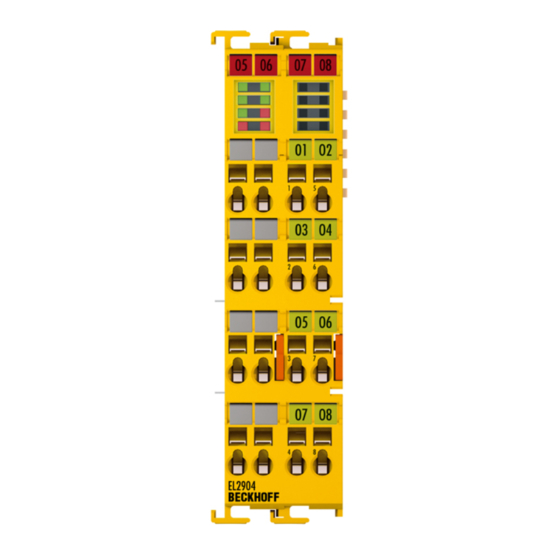
Product description EL2904 – TwinSAFE terminal with 4 digital fail-safe outputs The EL2904 is a safe output terminal with digital outputs for connecting actuators (contactors, relays, etc.) with a maximum current 0.5 A (24 V ). The Bus Terminal has 4 fail-safe outputs. -
Page 20: Intended Use
Test pulses When selecting actuators please ensure that the EL2904 test pulses do not lead to actuator switching or diagnostic message from the EL2904. The following TwinSAFE components have been developed for these tasks: •... - Page 21 EN 60529, so that the requirement for degree of pollution 3 according to EN 60664-1 can be reduced to level 2. • The TwinSAFE components must be supplied by a SELV/PELV power supply unit with a maximum voltage of U ≤ 36 V EL2904 Version: 3.2.2...
-
Page 22: Technical Data
500 mA, min. 20 mA with Current Measurement Active parameter enabled Utilization category according to EN 60947-5-1 DC-13 Actuators When selecting actuators please ensure that the EL2904 test pulses do not lead to actuator switching. Cable length between actuator and terminal unshielded max. 100 m shielded max. 100 m Wire cross-section min. -
Page 23: Target Failure Measures
Product description Product designation EL2904 • Sulfur dioxide: (300 ± 20) ppb Protection rating IP20 Device type according to EN 61010-2-201 Open equipment Permitted operating environment In the control cabinet or terminal box, with minimum protection rating IP54 according to IEC 60529... -
Page 24: Dimensions
Element classification Type B 1. Special proof tests are not required during the entire lifetime of the EL2904 EtherCAT terminal. 2. Classification according to IEC 61508-2:2010 (chapter 7.4.4.1.2 and 7.4.4.1.3) The EL2904 EtherCAT Terminal can be used for safety-related applications within the meaning of IEC 61508:2010 up to SIL3 and EN ISO 13849-1:2015 up to PL e (Cat4). -
Page 25: Block Diagram Of The El2904
Fig. 6: Block diagram of the EL2904 The block diagram shows the basic configuration of a channel in the EL2904. The part with a red border is present four times in the terminal. The high-side and low-side switches only exist once for all channels. This means that each channel has a total of four stop paths. -
Page 26: Operation
The electric connections between the Bus Coupler and the Bus Terminals are automatically realized by joining the components: Spring contacts (E-bus) The six spring contacts of the E-bus deal with the transfer of the data and the supply of the Bus Terminal electronics. Version: 3.2.2 EL2904... -
Page 27: Fig. 7 Pe Power Contact
Power Feed Terminals can be released and pulled at least 10 mm from the group of terminals. DANGER Serious risk of injury! The PE power contact must not be used for other potentials! EL2904 Version: 3.2.2... -
Page 28: Fig. 8 Connection Of A Cable To A Terminal Point
See the following table for the suitable wire size width. Wire size width (single core wires) 0.08 ... 2.5 mm Wire size width (fine-wire conductors) 0.08 ... 2.5 mm Wire size width (conductors with a wire end sleeve) 0.14 ... 1.5 mm Wire stripping length 8 ... 9 mm Version: 3.2.2 EL2904... -
Page 29: Fig. 9 El2904 Pin Assignment
Output 3- 5’ Output 2+ 6’ Output 2- 7’ Output 4+ 8’ Output 4- Test pulses When selecting actuators please ensure that the EL2904 test pulses do not lead to actuator switching or diagnostic message from the EL2904. EL2904 Version: 3.2.2... -
Page 30: Fig. 10 Permitted Cable Length
When connecting a single actuator via its own continuous cabling (or via a sheathed cable), the maximum permitted cable length is 100 m. The use of contact points, connectors or additional actuators in the cabling reduces the maximum propagation. Cable routing Fig. 11: Cable routing Version: 3.2.2 EL2904... -
Page 31: Mechanical Installation
5 to 7 times per second. Test pulses for the outputs The following diagram shows a typical test pulse curve for the four outputs of an EL2904. The parameters Current measurement active and Testing of outputs active are enabled. -
Page 32: Fig. 13 Installation Position And Minimum Distances
Fig. 13: Installation position and minimum distances In order to ensure optimum convection cooling, the distances to neighboring devices and to control cabinet walls must not be smaller than those shown in the diagram. Version: 3.2.2 EL2904... -
Page 33: Fig. 14 Example Configuration For Temperature Measurement
The key parameter is always the maximum permitted internally measured temperature of 95°C, above which the TwinSAFE terminals switch to safe state and report an error. The internal temperature can be read from the TwinSAFE components via CoE (see chapter Diagnose). EL2904 Version: 3.2.2... -
Page 34: Twinsafe Reaction Times
The typical response time is based on the following formula: ReactionTime Sensor Input Comm Logic Comm Output Actuator with ReactionTime Worst case response time The worst-case response time is the maximum time required for switching off the actuator in the event of an error. Version: 3.2.2 EL2904... -
Page 35: Tested El2904 Devices
5.2.6 Tested EL2904 devices The following list contains devices that were tested together with the EL2904 TwinSAFE terminal. The results only apply for the current device hardware version at the time of testing. The tests were carried out in a laboratory environment. Modifications of these products cannot be considered here. If you are unsure please test the hardware together with the TwinSAFE terminal. -
Page 36: Operation In Potentially Explosive Atmospheres (Atex)
• EN 60079-15: 2005 5.3.2 Identification Beckhoff fieldbus components that are certified for use in potentially explosive atmospheres bear one of the following markings: II 3 G Ex nA IIC T4 Gc KEMA 10ATEX0075 X Ta: 0 … 55 °C II 3 G Ex nA nC IIC T4 Gc KEMA 10ATEX0075 X Ta: 0 …... -
Page 37: Date Code And Serial Number
Inserting a Bus Terminal See TwinCAT automation software documentation. 5.4.3 Inserting an EL2904 An EL2904 is inserted in the same way as any other Beckhoff Bus Terminal. In the list open Safety Terminals (ELx9xx) and select the EL2904. EL2904 Version: 3.2.2... -
Page 38: Fig. 17 Inserting An El2904
Operation Fig. 17: Inserting an EL2904 Version: 3.2.2 EL2904... -
Page 39: Address Settings On Twinsafe Terminals With 1023 Possible Addresses
TwinSAFE terminal. TwinSAFE addresses between 1 and 1023 are available. DIP switch Address 1023 WARNING TwinSAFE address Each TwinSAFE address may only be used once within a network / a configuration! The address 0 is not a valid TwinSAFE address! EL2904 Version: 3.2.2... -
Page 40: Entering A Twinsafe Address And Parameters In The System Manager
The FSoE address set at the DIP switch must also be entered under the FSoE tab (FSoE Address entry). Fig. 19: Entering the FSoE address The EL2904 parameters are set under the respective TwinSAFE connection in the Connection and Parameter tabs. -
Page 41: Fig. 21 Setting The Parameters Of The Twinsafe Connection
Performance Level see Application Guide. monitoring Short circuit FALSE TRUE Test pulses at output monitoring Current measurement inactive Performance Level see Application Guide. FALSE FALSE No test pulses at the output monitoring Current measurement inactive Performance Level see Application Guide. EL2904 Version: 3.2.2... -
Page 42: Diagnostics
Diag 3 (red) and Diag 4 (red) If the Diag 3 LED is lit, the Diag 4 LED indicates internal terminal errors. These errors lead to shutdown of the terminal. The terminal must be checked by Beckhoff Automation GmbH & Co. KG. -
Page 43: Diagnostic Objects
Operation Flashing Code In the case of such an error, the Diag 4 LED on the EL2904 displays flashing codes that describe the error in more detail. A flashing code consists of four sequences, which are interrupted in each case by a short break. After the four sequences there is a long break, following which the flashing code is displayed again. -
Page 44: Possible Causes Of Diagnostic Messages
Comply with the specified temperature range Flash code 7 EMC faults Take suitable EMC measures Internal defect Replace terminal Diag 2 LED Terminal temperature too high Comply with the specified temperature range Flash code 8 EMC faults Take suitable EMC measures Version: 3.2.2 EL2904... - Page 45 Check the installation position of the terminal and modify it according to the specifications in section Mechanical An internal measuring point shows an elevated installation, if required temperature due to inadequate convection. EMC faults Take suitable EMC measures Internal defect Replace terminal EL2904 Version: 3.2.2...
-
Page 46: Lifetime
CW: calendar week of manufacture Calendar week: 17 JJ: year of manufacture Year: 2011 SW: software version Software version: 05 HW: hardware version Hardware version: 00 In addition the TwinSAFE components bear a unique serial number. 00000000 17110500 Version: 3.2.2 EL2904... -
Page 47: Maintenance And Cleaning
1. Pull the orange strap [2] approx. 1 cm out of the TwinSAFE component [1] The mounting rail lock of the TwinSAFE component releases automatically. 2. Use your thumb and index finger to grip the unlocked TwinSAFE component [1] simultaneously at the top and bottom of the housing surfaces EL2904 Version: 3.2.2... - Page 48 Maintenance and cleaning 3. Pull the TwinSAFE component [1] out of the bus terminal block from the mounting rail [3] with little effort Version: 3.2.2 EL2904...
-
Page 49: Decommissioning
In accordance with the WEEE-2012/19/EU directives, you can return used devices and accessories for professional disposal. The transport costs are borne by the sender. Send the used devices with the note "For disposal" to: Beckhoff Automation GmbH & Co. KG Gebäude „Service“ Stahlstraße 31... -
Page 50: Appendix
If there is customer specific data saved on the product, it cannot be ensured that this data might not be restored through for example forensic measures, even after the data is deleted through the provided tool chain. If this data is confidential, the scrapping of the product after usage is recommended to protect this data. Version: 3.2.2 EL2904... -
Page 51: Focus Of Certificates
The current certificates of all TwinSAFE components with the underlying standards and directives can be found at https://www.beckhoff.com/en-en/support/download-finder/certificates-approvals/. If the document refers only to the first four figures of a product (ELxxxx), the certificate is valid for all available variants of the component (ELxxxx-abcd). - Page 52 Fig. 2 Bus Coupler (EtherCAT) ......................Fig. 3 TwinSAFE Terminals (EtherCAT) ....................Fig. 4 EL2904 – TwinSAFE terminal with 4 digital fail-safe outputs............Fig. 5 Dimensions of the EL2904 ......................Fig. 6 Block diagram of the EL2904 ....................... Fig. 7 PE power contact .........................
- Page 54 More Information: www.beckhoff.com/EL2904 Beckhoff Automation GmbH & Co. KG Hülshorstweg 20 33415 Verl Germany Phone: +49 5246 9630 info@beckhoff.com www.beckhoff.com...
Need help?
Do you have a question about the EL2904 and is the answer not in the manual?
Questions and answers