
Related Manuals for Beckhoff EL6652-00 0 Series


Summary of Contents for Beckhoff EL6652-00 0 Series
- Page 1 Documentation EL6652-00x0 EtherNet/IP Master/Slave EtherCAT Terminal Version: Date: 2019-10-22...
-
Page 3: Table Of Contents
Notes on the documentation...................... 5 Safety instructions .......................... 6 Documentation issue status ...................... 7 Version identification of EtherCAT devices .................. 8 1.4.1 Beckhoff Identification Code (BIC)................... 12 2 Product overview............................. 14 EL6652-0000, EL6652-0010 - Introduction .................. 14 EL6652-0000, EL6652-0010 - Technical data ................. 16 3 Basics communication ........................... 17 EtherCAT basics.......................... 17... - Page 4 Table of contents 5.6.2 EL6652-0010 - Configuration parameters .............. 115 5.6.3 Master (Scanner) configuration .................. 116 6 Configuration with the Twincat System Manager................ 121 Object description and parameterization .................. 121 7 Diagnosis.............................. 126 EL6652-0010 - LEDs ........................ 126 EL6652-0000, EL6652-0010 diagnostic history................ 128 8 Appendix .............................. 130 Firmware Update EL/ES/EM/ELM/EPxxxx .................. 130 8.1.1 Device description ESI file/XML..................
-
Page 5: Foreword
EP1590927, EP1789857, EP1456722, EP2137893, DE102015105702 with corresponding applications or registrations in various other countries. ® EtherCAT is registered trademark and patented technology, licensed by Beckhoff Automation GmbH, Germany. Copyright © Beckhoff Automation GmbH & Co. KG, Germany. The reproduction, distribution and utilization of this document as well as the communication of its contents to others without express authorization are prohibited. -
Page 6: Safety Instructions
All the components are supplied in particular hardware and software configurations appropriate for the application. Modifications to hardware or software configurations other than those described in the documentation are not permitted, and nullify the liability of Beckhoff Automation GmbH & Co. KG. Personnel qualification This description is only intended for trained specialists in control, automation and drive engineering who are familiar with the applicable national standards. -
Page 7: Documentation Issue Status
Foreword Documentation issue status Version Comment • Update revision status • Update structure • Update chapter "Changing EthetNet/IP Setting" • Update revision status • Update structure • Update Technical data • Addenda chapter "Instructions for ESD protection" • Addenda chapter "UL notice" •... -
Page 8: Version Identification Of Ethercat Devices
Production lot/batch number/serial number/date code/D number The serial number for Beckhoff IO devices is usually the 8-digit number printed on the device or on a sticker. The serial number indicates the configuration in delivery state and therefore refers to a whole production batch, without distinguishing the individual modules of a batch. -
Page 9: Fig. 1 El5021 El Terminal, Standard Ip20 Io Device With Serial/ Batch Number And Revision Id (Since 2014/01)
Foreword Example with Ser. no.: 12063A02: 12 - production week 12 06 - production year 2006 3A - firmware version 3A 02 - hardware version 02 Exceptions can occur in the IP67 area, where the following syntax can be used (see respective device documentation): Syntax: D ww yy x y z u D - prefix designation... -
Page 10: Fig. 2 Ek1100 Ethercat Coupler, Standard Ip20 Io Device With Serial/ Batch Number
Foreword Fig. 2: EK1100 EtherCAT coupler, standard IP20 IO device with serial/ batch number Fig. 3: CU2016 switch with serial/ batch number Fig. 4: EL3202-0020 with serial/ batch number 26131006 and unique ID-number 204418 Version: 2.5 EL6652-00x0... -
Page 11: Fig. 5 Ep1258-00001 Ip67 Ethercat Box With Batch Number/ Date Code 22090101 And Unique Se- Rial Number 158102
Foreword Fig. 5: EP1258-00001 IP67 EtherCAT Box with batch number/ date code 22090101 and unique serial number 158102 Fig. 6: EP1908-0002 IP67 EtherCAT Safety Box with batch number/ date code 071201FF and unique serial number 00346070 Fig. 7: EL2904 IP20 safety terminal with batch number/ date code 50110302 and unique serial number 00331701 Fig. 8: ELM3604-0002 terminal with unique ID number (QR code) 100001051 and serial/ batch number 44160201... -
Page 12: Beckhoff Identification Code (Bic)
1.4.1 Beckhoff Identification Code (BIC) The Beckhoff Identification Code (BIC) is increasingly being applied to Beckhoff products to uniquely identify the product. The BIC is represented as a Data Matrix Code (DMC, code scheme ECC200), the content is based on the ANSI standard MH10.8.2-2016. - Page 13 Example of composite information from item 1 to 4 and 6. The data identifiers are marked in red for better display: An important component of the BIC is the Beckhoff Traceability Number (BTN, item no. 2). The BTN is a unique serial number consisting of eight characters that will replace all other serial number systems at Beckhoff in the long term (e.g.
-
Page 14: Product Overview
Product overview Product overview EL6652-0000, EL6652-0010 - Introduction Ethernet/IP Master Fig. 10: EL6652-0000 The EL6652 EtherNet/IP-Master Terminal has a switched 2-port Ethernet connection and can thus be operated in a line with further Ethernet/IP nodes. The process data are configured by an EtherCAT master, allowing different process data and different sizes. -
Page 15: Fig. 11 El6652-0010
Product overview Ethernet/IP Slave Fig. 11: EL6652-0010 The EtherNet/IP Slave terminal enables the exchange of data with an EtherNet/IP scanner or a master. Both Multicast and Unicast are supported. The terminal can behave like two EtherNet/IP slave devices. The second slave is a virtual slave. This enables you to connect two masters together or one master with two slaves and, for example, to transport more data or to operate with different polling times on the master. -
Page 16: El6652-0000, El6652-0010 - Technical Data
Product overview EL6652-0000, EL6652-0010 - Technical data Technical data EL6652 EL6652-0010 Description Master (Scanner) Slave Number of possible slave devices 16 slaves Number of ports/channels 2 (switched) Ethernet interface 100 MB Ethernet with 2 x RJ45 Data width max. 1 kByte input and 1 kByte output data Cable length up to 100 m Twisted-Pair Hardware diagnosis... -
Page 17: Basics Communication
EtherCAT devices from Beckhoff. Recommended cables Suitable cables for the connection of EtherCAT devices can be found on the Beckhoff website! E-Bus supply A bus coupler can supply the EL terminals added to it with the E-bus system voltage of 5 V; a coupler is thereby loadable up to 2 A as a rule (see details in respective device documentation). -
Page 18: General Notes For Setting The Watchdog
Basics communication Fig. 12: System manager current calculation NOTE Malfunction possible! The same ground potential must be used for the E-Bus supply of all EtherCAT terminals in a terminal block! General notes for setting the watchdog ELxxxx terminals are equipped with a safety feature (watchdog) that switches off the outputs after a specifiable time e.g. -
Page 19: Fig. 13 Ethercat Tab -> Advanced Settings -> Behavior -> Watchdog
Basics communication Fig. 13: EtherCAT tab -> Advanced Settings -> Behavior -> Watchdog Notes: • the multiplier is valid for both watchdogs. • each watchdog has its own timer setting, the outcome of this in summary with the multiplier is a resulting time. -
Page 20: Ethercat State Machine
Basics communication Example "Set SM watchdog" This checkbox enables manual setting of the watchdog times. If the outputs are set and the EtherCAT communication is interrupted, the SM watchdog is triggered after the set time and the outputs are erased. This setting can be used for adapting a terminal to a slower EtherCAT master or long cycle times. -
Page 21: Fig. 14 States Of The Ethercat State Machine
Basics communication Fig. 14: States of the EtherCAT State Machine Init After switch-on the EtherCAT slave in the Init state. No mailbox or process data communication is possible. The EtherCAT master initializes sync manager channels 0 and 1 for mailbox communication. Pre-Operational (Pre-Op) During the transition between Init and Pre-Op the EtherCAT slave checks whether the mailbox was initialized correctly. -
Page 22: Coe Interface
Basics communication Boot In the Boot state the slave firmware can be updated. The Boot state can only be reached via the Init state. In the Boot state mailbox communication via the file access over EtherCAT (FoE) protocol is possible, but no other mailbox communication and no process data communication. -
Page 23: Fig. 15 "Coe Online " Tab
Data management If slave CoE parameters are modified online, Beckhoff devices store any changes in a fail-safe manner in the EEPROM, i.e. the modified CoE parameters are still available after a restart. The situation may be different with other manufacturers. -
Page 24: Fig. 16 Startup List In The Twincat System Manager
Changes in the local CoE list of the terminal are lost if the terminal is replaced. If a terminal is re- placed with a new Beckhoff terminal, it will have the default settings. It is therefore advisable to link all changes in the CoE list of an EtherCAT slave with the Startup list of the slave, which is pro- cessed whenever the EtherCAT fieldbus is started. -
Page 25: Fig. 17 Offline List
Basics communication Fig. 17: Offline list • If the slave is online ◦ The actual current slave list is read. This may take several seconds, depending on the size and cycle time. ◦ The actual identity is displayed ◦ The firmware and hardware version of the equipment according to the electronic information is displayed ◦... - Page 26 • Channel 1: parameter range 0x8010:00 ... 0x801F:255 • Channel 2: parameter range 0x8020:00 ... 0x802F:255 • ... This is generally written as 0x80n0. Detailed information on the CoE interface can be found in the EtherCAT system documentation on the Beckhoff website. Version: 2.5 EL6652-00x0...
-
Page 27: Distributed Clock
Basics communication Distributed Clock The distributed clock represents a local clock in the EtherCAT slave controller (ESC) with the following characteristics: • Unit 1 ns • Zero point 1.1.2000 00:00 • Size 64 bit (sufficient for the next 584 years; however, some EtherCAT slaves only offer 32-bit support, i.e. -
Page 28: Installation
• Each assembly must be terminated at the right hand end with an EL9011 or EL9012 bus end cap, to en- sure the protection class and ESD protection. Fig. 19: Spring contacts of the Beckhoff I/O components Recommended mounting rails Terminal Modules und EtherCAT Modules of KMxxxx and EMxxxx series, same as the terminals of the EL66xx and EL67xx series can be snapped onto the following recommended mounting rails: •... - Page 29 Installation Fixing of mounting rails The locking mechanism of the terminals and couplers extends to the profile of the mounting rail. At the installation, the locking mechanism of the components must not come into conflict with the fixing bolts of the mounting rail. To mount the recommended mounting rails under the terminals and cou- plers, you should use flat mounting connections (e.g.
- Page 30 Installation • Pull (4) the terminal module away from the mounting surface. Avoid canting of the module; you should stabilize the module with the other hand, if required. Version: 2.5 EL6652-00x0...
-
Page 31: Positioning Of Passive Terminals
Installation Positioning of passive Terminals Hint for positioning of passive terminals in the bus terminal block EtherCAT Terminals (ELxxxx / ESxxxx), which do not take an active part in data transfer within the bus terminal block are so called passive terminals. The passive terminals have no current consump- tion out of the E-Bus. -
Page 32: Fig. 22 Recommended Distances For Standard Installation Position
Installation Optimum installation position (standard) The optimum installation position requires the mounting rail to be installed horizontally and the connection surfaces of the EL/KL terminals to face forward (see Fig. “Recommended distances for standard installation position”). The terminals are ventilated from below, which enables optimum cooling of the electronics through convection. -
Page 33: Ul Notice
Beckhoff EtherCAT modules are intended for use with Beckhoff’s UL Listed EtherCAT Sys- tem only. Examination For cULus examination, the Beckhoff I/O System has only been investigated for risk of fire and electrical shock (in accordance with UL508 and CSA C22.2 No. 142). For devices with Ethernet connectors Not for connection to telecommunication circuits. -
Page 34: Commissioning
• "offline": The configuration can be customized by adding and positioning individual components. These can be selected from a directory and configured. ◦ The procedure for offline mode can be found under http://infosys.beckhoff.com: TwinCAT 2 → TwinCAT System Manager → IO - Configuration → Adding an I/O Device •... -
Page 35: Fig. 24 Relationship Between User Side (Commissioning) And Installation
Commissioning Fig. 24: Relationship between user side (commissioning) and installation The user inserting of certain components (I/O device, terminal, box...) is the same in TwinCAT 2 and TwinCAT 3. The descriptions below relate to the online procedure. Sample configuration (actual configuration) Based on the following sample configuration, the subsequent subsections describe the procedure for TwinCAT 2 and TwinCAT 3: •... -
Page 36: Fig. 25 Control Configuration With Embedded Pc, Input (El1004) And Output (El2008)
Commissioning Fig. 25: Control configuration with Embedded PC, input (EL1004) and output (EL2008) Note that all combinations of a configuration are possible; for example, the EL1004 terminal could also be connected after the coupler, or the EL2008 terminal could additionally be connected to the CX2040 on the right, in which case the EK1100 coupler wouldn’t be necessary. -
Page 37: Fig. 26 Initial Twincat 2 User Interface
Commissioning 5.1.1 TwinCAT 2 Startup TwinCAT basically uses two user interfaces: the TwinCAT System Manager for communication with the electromechanical components and TwinCAT PLC Control for the development and compilation of a controller. The starting point is the TwinCAT System Manager. After successful installation of the TwinCAT system on the PC to be used for development, the TwinCAT 2 System Manager displays the following user interface after startup: Fig. 26: Initial TwinCAT 2 user interface... -
Page 38: Fig. 27 Selection Of The Target System
Commissioning Fig. 27: Selection of the target system Use "Search (Ethernet)..." to enter the target system. Thus a next dialog opens to either: • enter the known computer name after "Enter Host Name / IP:" (as shown in red) • perform a "Broadcast Search" (if the exact computer name is not known) •... -
Page 39: Fig. 29 Select "Scan Devices
Commissioning Adding devices In the configuration tree of the TwinCAT 2 System Manager user interface on the left, select "I/O Devices” and then right-click to open a context menu and select "Scan Devices…", or start the action in the menu bar . The TwinCAT System Manager may first have to be set to "Config mode" via or via menu “Actions"... -
Page 40: Fig. 31 Mapping Of The Configuration In The Twincat 2 System Manager
Commissioning Fig. 31: Mapping of the configuration in the TwinCAT 2 System Manager The whole process consists of two stages, which may be performed separately (first determine the devices, then determine the connected elements such as boxes, terminals, etc.). A scan can also be initiated by selecting "Device ..."... -
Page 41: Fig. 33 Twincat Plc Control After Startup
Commissioning ◦ Structured Text (ST) • Graphical languages ◦ Function Block Diagram (FBD) ◦ Ladder Diagram (LD) ◦ The Continuous Function Chart Editor (CFC) ◦ Sequential Function Chart (SFC) The following section refers to Structured Text (ST). After starting TwinCAT PLC Control, the following user interface is shown for an initial project: Fig. 33: TwinCAT PLC Control after startup Sample variables and a sample program have been created and stored under the name "PLC_example.pro": EL6652-00x0... -
Page 42: Fig. 34 Sample Program With Variables After A Compile Process (Without Variable Integration)
Commissioning Fig. 34: Sample program with variables after a compile process (without variable integration) Warning 1990 (missing "VAR_CONFIG") after a compile process indicates that the variables defined as external (with the ID "AT%I*" or "AT%Q*") have not been assigned. After successful compilation, TwinCAT PLC Control creates a "*.tpy"... -
Page 43: Fig. 36 Plc Project Integrated In The Plc Configuration Of The System Manager
Commissioning Select the PLC configuration "PLC_example.tpy" in the browser window that opens. The project including the two variables identified with "AT" are then integrated in the configuration tree of the System Manager: Fig. 36: PLC project integrated in the PLC configuration of the System Manager The two variables "bEL1004_Ch4"... -
Page 44: Fig. 38 Selecting Pdo Of Type Bool
Commissioning Fig. 38: Selecting PDO of type BOOL According to the default setting, certain PDO objects are now available for selection. In this sample the input of channel 4 of the EL1004 terminal is selected for linking. In contrast, the checkbox "All types" must be ticked for creating the link for the output variables, in order to allocate a set of eight separate output bits to a byte variable. -
Page 45: Fig. 40 Application Of A "Goto Link" Variable, Using "Main.bel1004_Ch4" As A Sample
Commissioning Fig. 40: Application of a "Goto Link" variable, using "MAIN.bEL1004_Ch4" as a sample The process of assigning variables to the PDO is completed via the menu selection "Actions" → "Generate Mappings”, key Ctrl+M or by clicking on the symbol in the menu. This can be visualized in the configuration: The process of creating links can also take place in the opposite direction, i.e. -
Page 46: Fig. 41 Choose Target System (Remote)
Commissioning Fig. 41: Choose target system (remote) In this sample "Runtime system 1 (port 801)" is selected and confirmed. Link the PLC with the real-time system via menu option "Online" → "Login", the F11 key or by clicking on the symbol . The control program can then be loaded for execution. - Page 47 Commissioning Fig. 42: PLC Control logged in, ready for program startup The PLC can now be started via "Online" → "Run", F5 key or 5.1.2 TwinCAT 3 Startup TwinCAT makes the development environment areas available together with Microsoft Visual Studio: after startup, the project folder explorer appears on the left in the general window area (cf.
- Page 48 Commissioning Fig. 43: Initial TwinCAT 3 user interface First create a new project via (or under "File"→“New"→ "Project…"). In the following dialog make the corresponding entries as required (as shown in the diagram): Fig. 44: Create new TwinCAT project The new project is then available in the project folder explorer: Version: 2.5 EL6652-00x0...
- Page 49 Commissioning Fig. 45: New TwinCAT3 project in the project folder explorer Generally, TwinCAT can be used in local or remote mode. Once the TwinCAT system including the user interface (standard) is installed on the respective PLC, TwinCAT can be used in local mode and thereby the next step is "Insert Device [} 50]".
- Page 50 Commissioning Use "Search (Ethernet)..." to enter the target system. Thus a next dialog opens to either: • enter the known computer name after "Enter Host Name / IP:" (as shown in red) • perform a "Broadcast Search" (if the exact computer name is not known) •...
- Page 51 Commissioning Fig. 49: Automatic detection of I/O devices: selection the devices to be integrated Confirm the message "Find new boxes", in order to determine the terminals connected to the devices. "Free Run" enables manipulation of input and output values in "Config mode" and should also be acknowledged. Based on the sample configuration [} 35] described at the beginning of this section, the result is as follows: Fig. 50: Mapping of the configuration in VS shell of the TwinCAT3 environment The whole process consists of two stages, which may be performed separately (first determine the devices,...
- Page 52 Commissioning Fig. 51: Reading of individual terminals connected to a device This functionality is useful if the actual configuration is modified at short notice. Programming the PLC TwinCAT PLC Control is the development environment for the creation of the controller in different program environments: TwinCAT PLC Control supports all languages described in IEC 61131-3.
- Page 53 Commissioning Fig. 52: Adding the programming environment in "PLC" In the dialog that opens select "Standard PLC project" and enter "PLC_example" as project name, for example, and select a corresponding directory: Fig. 53: Specifying the name and directory for the PLC programming environment The "Main"...
- Page 54 Commissioning Fig. 54: Initial "Main" program of the standard PLC project To continue, sample variables and a sample program have now been created: Version: 2.5 EL6652-00x0...
- Page 55 Commissioning Fig. 55: Sample program with variables after a compile process (without variable integration) The control program is now created as a project folder, followed by the compile process: Fig. 56: Start program compilation The following variables, identified in the ST/ PLC program with "AT%", are then available in under "Assignments"...
- Page 56 Commissioning Fig. 57: Creating the links between PLC variables and process objects In the window that opens, the process object for the variable "bEL1004_Ch4" of type BOOL can be selected from the PLC configuration tree: Fig. 58: Selecting PDO of type BOOL According to the default setting, certain PDO objects are now available for selection.
- Page 57 Commissioning Fig. 59: Selecting several PDOs simultaneously: activate "Continuous" and "All types" Note that the "Continuous" checkbox was also activated. This is designed to allocate the bits contained in the byte of the variable "nEL2008_value" sequentially to all eight selected output bits of the EL2008 terminal. In this way it is possible to subsequently address all eight outputs of the terminal in the program with a byte corresponding to bit 0 for channel 1 to bit 7 for channel 8 of the PLC.
- Page 58 Commissioning Activation of the configuration The allocation of PDO to PLC variables has now established the connection from the controller to the inputs and outputs of the terminals. The configuration can now be activated with or via the menu under "TwinCAT"...
-
Page 59: Twincat 2
5.2.1 Installation of the TwinCAT real-time driver In order to assign real-time capability to a standard Ethernet port of an IPC controller, the Beckhoff real-time driver has to be installed on this port under Windows. This can be done in several ways. One option is described here. - Page 60 Commissioning Fig. 62: System Manager “Options” (TwinCAT 2) This have to be called up by the Menü “TwinCAT” within the TwinCAT 3 environment: Fig. 63: Call up under VS Shell (TwinCAT 3) The following dialog appears: Fig. 64: Overview of network interfaces Interfaces listed under “Compatible devices” can be assigned a driver via the “Install” button. A driver should only be installed on compatible devices.
- Page 61 Commissioning Fig. 65: EtherCAT device properties(TwinCAT 2): click on „Compatible Devices…“ of tab “Adapter” TwinCAT 3: the properties of the EtherCAT device can be opened by double click on “Device .. (EtherCAT)” within the Solution Explorer under “I/O”: After the installation the driver appears activated in the Windows overview for the network interface (Windows Start →...
- Page 62 Commissioning Fig. 67: Exemplary correct driver setting for the Ethernet port Other possible settings have to be avoided: Version: 2.5 EL6652-00x0...
- Page 63 Commissioning Fig. 68: Incorrect driver settings for the Ethernet port EL6652-00x0 Version: 2.5...
- Page 64 Commissioning IP address of the port used IP address/DHCP In most cases an Ethernet port that is configured as an EtherCAT device will not transport general IP packets. For this reason and in cases where an EL6601 or similar devices are used it is useful to specify a fixed IP address for this port via the “Internet Protocol TCP/IP”...
-
Page 65: Notes Regarding Esi Device Description
The files are read (once) when a new System Manager window is opened, if they have changed since the last time the System Manager window was opened. A TwinCAT installation includes the set of Beckhoff ESI files that was current at the time when the TwinCAT build was created. - Page 66 1018 in the configuration. This is also stated by the Beckhoff compatibility rule. Refer in particular to the chapter ‘General notes on the use of Beckhoff EtherCAT IO components’ and for manual configuration to the chapter ‘Offline configuration creation’ [} 70].
- Page 67 Commissioning Fig. 73: File OnlineDescription.xml created by the System Manager Is a slave desired to be added manually to the configuration at a later stage, online created slaves are indicated by a prepended symbol “>” in the selection list (see Figure “Indication of an online recorded ESI of EL2521 as an example”).
- Page 68 Commissioning Reasons may include: • Structure of the *.xml does not correspond to the associated *.xsd file → check your schematics • Contents cannot be translated into a device description → contact the file manufacturer Version: 2.5 EL6652-00x0...
-
Page 69: Twincat Esi Updater
Commissioning 5.2.3 TwinCAT ESI Updater For TwinCAT 2.11 and higher, the System Manager can search for current Beckhoff ESI files automatically, if an online connection is available: Fig. 76: Using the ESI Updater (>= TwinCAT 2.11) The call up takes place under: “Options” → "Update EtherCAT Device Descriptions"... -
Page 70: Offline Configuration Creation
Commissioning • the devices/modules be connected to the power supply and ready for communication • TwinCAT must be in CONFIG mode on the target system. The online scan process consists of: • detecting the EtherCAT device [} 75] (Ethernet port at the IPC) •... - Page 71 Commissioning This query may appear automatically when the EtherCAT device is created, or the assignment can be set/ modified later in the properties dialog; see Fig. “EtherCAT device properties (TwinCAT 2)”. Fig. 81: EtherCAT device properties (TwinCAT 2) TwinCAT 3: the properties of the EtherCAT device can be opened by double click on “Device .. (EtherCAT)” within the Solution Explorer under “I/O”: Selecting the Ethernet port Ethernet ports can only be selected for EtherCAT devices for which the TwinCAT real-time driver is...
- Page 72 (i.e. highest) revision and therefore the latest state of production is displayed in the selection dialog for Beckhoff devices. To show all device revisions available in the system as ESI descriptions tick the “Show Hidden Devices” check box, see Fig. “Display of previous revisions”.
- Page 73 If current ESI descriptions are available in the TwinCAT system, the last revision offered in the selection dialog matches the Beckhoff state of production. It is recommended to use the last device revision when creating a new configuration, if current Beckhoff devices are used in the real application. Older revisions should only be used if older devices from stock are to be used in the application.
- Page 74 Commissioning Fig. 87: EtherCAT terminal in the TwinCAT tree (left: TwinCAT 2; right: TwinCAT 3) Version: 2.5 EL6652-00x0...
-
Page 75: Online Configuration Creation
Commissioning 5.2.6 ONLINE configuration creation Detecting/scanning of the EtherCAT device The online device search can be used if the TwinCAT system is in CONFIG mode. This can be indicated by a symbol right below in the information bar: • on TwinCAT 2 by a blue display “Config Mode” within the System Manager window: •... - Page 76 [} 80] with the defined initial configuration.Background: since Beckhoff occasionally increases the revision version of the delivered products for product maintenance reasons, a configuration can be created by such a scan which (with an identical machine construction) is identical according to the device list;...
- Page 77 Likewise, A might create spare parts stores worldwide for the coming series-produced machines with EL2521-0025-1018 terminals. After some time Beckhoff extends the EL2521-0025 by a new feature C. Therefore the FW is changed, outwardly recognizable by a higher FW version and a new revision -1019. Nevertheless the new device naturally supports functions and interfaces of the predecessor version(s);...
- Page 78 Commissioning Fig. 96: Manual triggering of a device scan on a specified EtherCAT device (left: TwinCAT 2; right: TwinCAT 3) In the System Manager (TwinCAT 2) or the User Interface (TwinCAT 3) the scan process can be monitored via the progress bar at the bottom in the status bar. Fig. 97: Scan progressexemplary by TwinCAT 2 The configuration is established and can then be switched to online state (OPERATIONAL).
- Page 79 Commissioning Fig. 101: Online display example Please note: • all slaves should be in OP state • the EtherCAT master should be in “Actual State” OP • “frames/sec” should match the cycle time taking into account the sent number of frames •...
- Page 80 A ‘ChangeTo’ or ‘Copy’ should only be carried out with care, taking into consideration the Beckhoff IO compatibility rule (see above). The device configuration is then replaced by the revision found; this can affect the supported process data and functions.
- Page 81 If current ESI descriptions are available in the TwinCAT system, the last revision offered in the selection dialog matches the Beckhoff state of production. It is recommended to use the last device revision when creating a new configuration, if current Beckhoff devices are used in the real application. Older revisions should only be used if older devices from stock are to be used in the application.
- Page 82 Commissioning Fig. 106: Correction dialog with modifications Once all modifications have been saved or accepted, click “OK” to transfer them to the real *.tsm configuration. Change to Compatible Type TwinCAT offers a function “Change to Compatible Type…” for the exchange of a device whilst retaining the links in the task.
-
Page 83: Ethercat Subscriber Configuration
Commissioning If called, the System Manager searches in the procured device ESI (in this example: EL1202-0000) for details of compatible devices contained there. The configuration is changed and the ESI-EEPROM is overwritten at the same time – therefore this process is possible only in the online state (ConfigMode). 5.2.7 EtherCAT subscriber configuration In the left-hand window of the TwinCAT 2 System Manager or the Solution Explorer of the TwinCAT 3... - Page 84 Commissioning „EtherCAT“ tab Fig. 111: „EtherCAT“ tab Type EtherCAT device type Product/Revision Product and revision number of the EtherCAT device Auto Inc Addr. Auto increment address of the EtherCAT device. The auto increment address can be used for addressing each EtherCAT device in the communication ring through its physical position.
- Page 85 For Beckhoff EtherCAT EL, ES, EM, EJ and EP slaves the following applies in general: • The input/output process data supported by the device are defined by the manufacturer in the ESI/XML description.
- Page 86 Commissioning Fig. 113: Configuring the process data Manual modification of the process data According to the ESI description, a PDO can be identified as “fixed” with the flag “F” in the PDO overview (Fig. “Configuring the process data”, J). The configuration of such PDOs cannot be changed, even if TwinCAT offers the associated dialog (“Edit”).
- Page 87 Commissioning Fig. 114: „Startup“ tab Column Description Transition Transition to which the request is sent. This can either be • the transition from pre-operational to safe-operational (PS), or • the transition from safe-operational to operational (SO). If the transition is enclosed in "<>" (e.g. <PS>), the mailbox request is fixed and cannot be modified or deleted by the user.
- Page 88 Commissioning Fig. 115: “CoE – Online” tab Object list display Column Description Index Index and sub-index of the object Name Name of the object Flags The object can be read, and data can be written to the object (read/write) The object can be read, but no data can be written to the object (read only) An additional P identifies the object as a process data object.
- Page 89 Commissioning Fig. 116: Dialog “Advanced settings” Online - via SDO Information If this option button is selected, the list of the objects included in the object list of the slave is uploaded from the slave via SDO information. The list below can be used to specify which object types are to be uploaded. Offline - via EDS File If this option button is selected, the list of the objects included in the object list is read from an EDS file provided by the user.
- Page 90 Fig. 118: "DC" tab (Distributed Clocks) Operation Mode Options (optional): • FreeRun • SM-Synchron • DC-Synchron (Input based) • DC-Synchron Advanced Settings… Advanced settings for readjustment of the real time determinant TwinCAT- clock Detailed information to Distributed Clocks are specified on http://infosys.beckhoff.com: Version: 2.5 EL6652-00x0...
- Page 91 Commissioning Fieldbus Components → EtherCAT Terminals → EtherCAT System documentation → EtherCAT basics → Distributed Clocks 5.2.7.1 Detailed description of Process Data tab Sync Manager Lists the configuration of the Sync Manager (SM). If the EtherCAT device has a mailbox, SM0 is used for the mailbox output (MbxOut) and SM1 for the mailbox input (MbxIn).
- Page 92 Commissioning PDO Content Indicates the content of the PDO. If flag F (fixed content) of the PDO is not set the content can be modified. Download If the device is intelligent and has a mailbox, the configuration of the PDO and the PDO assignments can be downloaded to the device.
-
Page 93: Basic Function Principles
We recommend downloading the latest EtherCAT Device Description from the download area on the Beckhoff website and installing it according to the installation instructions. The process image is freely configurable. In this way it is possible to reduce the process data for internal application to a minimum. -
Page 94: Changing Ethernet/Ip Settings
Commissioning Changing EtherNet/IP settings With the following products the settings can also be changed by ADS. • TS6280-xxxx | TwinCAT EtherNet/IP Slave (excluding Legacy Device), from TwinCAT Build 2249 • TS6281-xxxx | TwinCAT EtherNet/IP Master, from TwinCAT Build 2249 • EL6652 | EtherNet/IP Master Terminal (from software version 01V0.36) •... - Page 95 Commissioning Setting for setting (4 bytes + object size (256 bytes)) Byte Offset 0: 0x45 Byte Offset 1: 0x23 Byte Offset 2: ObjIndex LoByte (e.g. 0x8000 for Slave 1 and 0x8010 for Slave 2 and 0xF800 for the Master) Byte Offset 3: ObjIndex HiByte Byte Offset 4-260: Data of the object (see object description below) Setting for resetting (4 bytes) Byte Offset 0: 0x00...
-
Page 96: El6652-0000 Master (Scanner)
IDXOFFS:0x00000000 LEN: 256 The data are saved in the data array as described above. Example for TwinCAT 2.11 R3 and EL6652 or EL6652-0010, reading and writing the IP setting: https://infosys.beckhoff.com/content/1033/el6652/Resources/zip/1405400587.zip EL6652-0000 Master (Scanner) 5.5.1 EL 6652-0000 configuration The EL6652 EtherCAT Terminal is a simple Ethernet/IP Master and supports the exchange of process data without configuration data. - Page 97 Commissioning Fig. 121: Inserting the EL6652-0000 in TwinCAT 2.1x As soon as you have appended the terminal you must also create the "EtherNet/IP" device in the System Manager. Go onto "I/O devices" and append a further device. Fig. 122: Insert a device "EtherNet/IP" in "I/O devices" Under "EtherNet/IP"...
- Page 98 Commissioning If you have only one EL6652 in your system, the System Manager links it automatically. You should nevertheless check this (see fig. "Searching for the EL6652 terminal") by going onto the "EtherNet/IP Device" (1), "Adapter" (2) and then finding the terminal in the "Device Name". If that is not the case, go onto "Search"...
- Page 99 Commissioning Fig. 125: Configuration of the IP address, network mask and gateway address Now click on "Device1 (EL6652)" with the right mouse button and add a "Generic Ethernet/IP adapter". Alternatively you can search for Ethernet/IP devices (Scan Boxes…). Fig. 126: Add "Generic EtherNet/IP Adapter" You will now be requested to enter the IP address.
- Page 100 Commissioning The following dialog box appears (see the chapter EDS file [} 104] for the settings for this). Fig. 128: Dialog box "Add I/O Connection Object" Now append the variables that you want to use for the cyclic data exchange (these do not have to correspond to the EDS file in terms of type;...
- Page 101 Commissioning Task time The time with which the EtherNet/IP is to operate is specified with the SyncTask. Two methods are available here: SyncTask via Mapping – in this case the task is used with which the variables are linked. That is usually the PLC task.
- Page 102 Commissioning Fig. 131: Diagnosis of "ECatState" and "State" Version: 2.5 EL6652-00x0...
-
Page 103: El6652-0000 - Configuration Parameters
Commissioning 5.5.2 EL6652-0000 - Configuration parameters Index 0xF800 Scanner Settings Index Name Access Meaning F800:0 Master settings F800:1 Number Box Id F800:3 Product Name Name of the device F800:4 Device Type Device type F800:5 Vendor ID Vendor number F800:6 Product Code Product code F800:7 Revision... -
Page 104: El6652-0000 Eds File
System Manager. The example uses an EDS file of the type Endress+Hauser: Promass 100 EDS https://infosys.beckhoff.com/content/1033/el6652/Resources/zip/1405402763.zip Selection of a connection In the EDS file there are usually several connection options; in the yellow line you can see that the slave next to ‘connection 1’... - Page 105 Commissioning Fig. 132: Enter the values in the "Add IO Connection Object" dialog box Register the values according to the EDS file in the System Manager. Cycle Time Multiplier The EL6652 always operates internally with a cycle time of 1 millisecond. Some Ethernet/IP slaves are not designed for this time.
- Page 106 Commissioning This Ethernet/IP slave can handle a minimum of 5 ms (5000 µs); the manufacturer specifies a default value of 20 ms. It is advisable to follow the manufacturer’s specification and to use the 20 ms. This means that a "Cycle Time Multiplier"...
- Page 107 Commissioning The output data in the System Manager are illustrated below; first of all 8 bits are inserted, then 3 x byte, 6 x INT, 1 x DWord, 2 x INT, etc., until the length corresponds to 64 bytes. EL6652-00x0 Version: 2.5...
- Page 108 Commissioning Fig. 133: Output data in the System Manager The inputs Assem101 are handled analogously: On completion the configuration must look like the following: Version: 2.5 EL6652-00x0...
- Page 109 Commissioning Fig. 134: Configuration "IO Connection Object" Summary: Green: cycle time of the slave Blue: config parameter (size always 0) config instance 105 Yellow: input instance Len 88 connection point 101 Red: output instance Len 64 connection point 102 EL6652-00x0 Version: 2.5...
-
Page 110: El6652-0010 Slave
Commissioning EL6652-0010 Slave 5.6.1 EL 6652-0010 configuration The most important settings for establishing a connection with an EtherNet/I master or a scanner are IP address, the assembly instance number and thus the length of the data and the correct task cycle time. The IP address can be freely assigned and is transferred to the terminal during the EtherCAT start-up. - Page 111 Commissioning Fig. 137: Selection of adapter "EtherNet/IP adapter (EL6652-0010)" If you have only one EL6652-0010 in your system, the System Manager links it automatically. You should nevertheless check this (see fig. "Searching for the EL6652-0010 terminal") by going onto the "EtherNet/IP Device" (1), "Adapter" (2) and then finding the terminal in the "Device Name". If that is not the case, go onto "Search"...
- Page 112 Commissioning The MAC address and IP address are not updated in this dialog box. These can be found on the EtherNet/IP box under "Configuration". Configuration Now create a configuration; the master must configured with an IP address, SubNetMask and the data which are to be exchanged with the EtherNet/IP Master.
- Page 113 Commissioning Fig. 141: Append variables An IO assembly (0x8001) is now present in the configuration. The instance numbers must be observed for the entry in the master. • Value 128 for the configuration; as already mentioned, this is always to be used with "zero" bytes. •...
- Page 114 Commissioning SyncTask via Special Sync Task - in this case an additional task is used that is automatically started with TwinCAT. This runs in its own cycle and is therefore also independent of other tasks that are linked with the variables.
-
Page 115: El6652-0010 - Configuration Parameters
Commissioning 5.6.2 EL6652-0010 - Configuration parameters Index 0x8000 Slave Settings Index Name Meaning 8000:0 slave settings 8000:1 Slave Number Slave Box ID 8000:3 Product Name Name of the device 8000:4 Device Type Device type 8000:5 Vendor ID Vendor number 8000:6 Product Code Product code 8000:7... -
Page 116: Master (Scanner) Configuration
Commissioning Index 0x8001 IO Assembly Settings Index Name Meaning 8001:0 IO Assembly Settings 8001:1 Assembly Number Assembly Id 8001:1 Configuration Instance Config Instance 8001:3 Configuration Size Config Size (always 0) 8001:4 Input Instance (T->O) Connection Point for Input Data (Target->Originator) 8001:5 Input Size (T->O) Size of Input Data (in Bytes) - Page 117 Commissioning Fig. 144: Creating a new controller Append a new module. EL6652-00x0 Version: 2.5...
- Page 118 Commissioning Fig. 145: Appending a new module Select ETHERNET MODULE "Generic Ethernet Module". Version: 2.5 EL6652-00x0...
- Page 119 Commissioning Fig. 146: Selection of the ETHERNET MODULE "Generic Ethernet Module" Enter the IP address from object 0x8000:21. The input instance is to be entered as 129 , the output instance as 130 and the config instance as 128 . The data length is dependent on the Comm format. INT was selected in the illustration "Transferring the parameters into the "New modules"...
- Page 120 Commissioning Fig. 147: Transferring the parameters into the "New Modules" mask Version: 2.5 EL6652-00x0...
-
Page 121: Configuration With The Twincat System Manager
EtherCAT XML device description and configuration files We recommend downloading the latest EtherCAT Device Description from the download area on the Beckhoff website and installing it according to the installation instructions. Parameterization The terminal is parameterized via the CoE Online tab (with a double-click on the respective object, see below). - Page 122 Configuration with the Twincat System Manager Index 1018 Identity Index Name Meaning Format Flags Default value (hex) 1018:0 Identity Information for identifying the slave UINT8 0x04 (4 1018:01 Vendor ID Vendor ID of the EtherCAT slave UINT32 0x00000002 (2 1018:02 Product code Product code of the EtherCAT slave UINT32...
- Page 123 Configuration with the Twincat System Manager Index 1C32 SM output parameter Index Name Meaning Format Flags Default value (hex) 1C32:0 SM output parameter Synchronization parameters for the outputs UINT8 0x20 (32 1C32:01 Sync mode Current synchronization mode: UINT16 0x0000 (0 •...
- Page 124 Configuration with the Twincat System Manager Index 1C33 SM input parameter Index Name Meaning Format Flags Default value (hex) 1C33:0 SM input parameter Synchronization parameters for the inputs UINT8 0x20 (32 1C33:01 Sync mode Current synchronization mode: UINT16 0x0000 (0 •...
- Page 125 Configuration with the Twincat System Manager Index F008 Code word Index Name Meaning Format Flags Default value (hex) F008:0 Code word reserved UINT32 0x00000000 (0 Index F010 Module list Index Name Meaning Format Flags Default value (hex) F010:0 Module list Max.
-
Page 126: Diagnosis
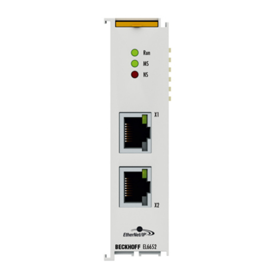
Diagnosis Diagnosis EL6652-0010 - LEDs Fig. 148: EL6652 LEDs LEDs for EtherCAT diagnosis Display Description green State of the EtherCAT state machine: INIT = initialization of the terminal; BOOTSTRAP = function for terminal firmware updates flashes (200 ms) State of the EtherCAT state machine: PREOP = function for mailbox communication and different standard- settings set off (1 s) - Page 127 Diagnosis LED EIP State Color green Color red Meaning no EtherNet/IP slave configuration on the EL6652-0010 All configured IO assemblies are in data exchange with the EtherNet/ IP master. All connections are in the run state (cyclic exchange of valid process data) off (1 s) EtherNet/IP slave and IO assembly are correctly parameterized on (200 ms)
-
Page 128: El6652-0000, El6652-0010 Diagnostic History
Diagnosis EL6652-0000, EL6652-0010 diagnostic history The diagnostic history is an aid for monitoring the status of the EtherNet/IP interface, the status of the terminal and the Ethernet port and to display the diagnostic messages in plain text with a time stamp. Furthermore, information/errors that occurred in the past or only briefly are also logged in order to also allow precise fault finding at a later time. - Page 129 Diagnosis Error Codes EL6652 Error Code Description Remedy CN_ORC_ALREADY_US 0x100 hex / 256 dec Connection already in use The connection is already established; use another connection or close this CN_ORC_BAD_TRANSP 0x103 hex / 259 dec Transport type not supported CN_ORC_OWNER_CON 0x106 hex / 262 dec More than one guy FLICT...
-
Page 130: Appendix
Appendix Appendix Firmware Update EL/ES/EM/ELM/EPxxxx This section describes the device update for Beckhoff EtherCAT slaves from the EL/ES, ELM, EM, EK and EP series. A firmware update should only be carried out after consultation with Beckhoff support. Storage locations An EtherCAT slave stores operating data in up to 3 locations: •... -
Page 131: Device Description Esi File/Xml
The device revision is closely linked to the firmware and hardware used. Incompatible combinations lead to malfunctions or even final shutdown of the device. Corresponding updates should only be carried out in consultation with Beckhoff support. Display of ESI slave identifier... - Page 132 Appendix Fig. 151: Scan the subordinate field by right-clicking on the EtherCAT device If the found field matches the configured field, the display shows Fig. 152: Configuration is identical otherwise a change dialog appears for entering the actual data in the configuration. Fig. 153: Change dialog In this example in Fig.
- Page 133 Appendix Changing the ESI slave identifier The ESI/EEPROM identifier can be updated as follows under TwinCAT: • Trouble-free EtherCAT communication must be established with the slave. • The state of the slave is irrelevant. • Right-clicking on the slave in the online display opens the EEPROM Update dialog, Fig. EEPROM Update Fig. 154: EEPROM Update The new ESI description is selected in the following dialog, see Fig.
-
Page 134: Firmware Explanation
• offline: The EtherCAT Slave Information ESI/XML may contain the default content of the CoE. This CoE directory can only be displayed if it is included in the ESI (e.g. "Beckhoff EL5xxx.xml"). The Advanced button must be used for switching between the two views. -
Page 135: Updating Controller Firmware *.Efw
Switch to the Online tab to update the controller firmware of a slave, see Fig. Firmware Update. Fig. 157: Firmware Update Proceed as follows, unless instructed otherwise by Beckhoff support. Valid for TwinCAT 2 and 3 as EtherCAT master. • Switch TwinCAT system to ConfigMode/FreeRun with cycle time >= 1 ms (default in ConfigMode is 4 ms). -
Page 136: Fpga Firmware *.Rbf
Appendix • Switch EtherCAT Master to PreOP • Switch slave to INIT (A) • Switch slave to BOOTSTRAP • Check the current status (B, C) • Download the new *efw file (wait until it ends). A pass word will not be neccessary usually. •... - Page 137 Appendix Fig. 158: FPGA firmware version definition If the column Reg:0002 is not displayed, right-click the table header and select Properties in the context menu. Fig. 159: Context menu Properties The Advanced Settings dialog appears where the columns to be displayed can be selected. Under Diagnosis/Online View select the '0002 ETxxxx Build' check box in order to activate the FPGA firmware version display.
- Page 138 Older firmware versions can only be updated by the manufacturer! Updating an EtherCAT device The following sequence order have to be met if no other specifications are given (e.g. by the Beckhoff support): • Switch TwinCAT system to ConfigMode/FreeRun with cycle time >= 1 ms (default in ConfigMode is 4 ms).
- Page 139 Appendix • In the TwinCAT System Manager select the terminal for which the FPGA firmware is to be updated (in the example: Terminal 5: EL5001) and click the Advanced Settings button in the EtherCAT tab: • The Advanced Settings dialog appears. Under ESC Access/E²PROM/FPGA click on Write FPGA button: EL6652-00x0 Version: 2.5...
-
Page 140: Simultaneous Updating Of Several Ethercat Devices
Appendix • Select the file (*.rbf) with the new FPGA firmware, and transfer it to the EtherCAT device: • Wait until download ends • Switch slave current less for a short time (don't pull under voltage!). In order to activate the new FPGA firmware a restart (switching the power supply off and on again) of the EtherCAT device is required. -
Page 141: Firmware Compatibility
Note • It is recommended to use the newest possible firmware for the respective hardware. • Beckhoff is not under any obligation to provide customers with free firmware updates for delivered products. NOTE Risk of damage to the device! Pay attention to the instructions for firmware updates on the separate page. -
Page 142: Support And Service
1819238756, Hexadecimal value: 0x6C6F6164An incorrect entry for the restore value has no effect. Support and Service Beckhoff and their partners around the world offer comprehensive support and service, making available fast and competent assistance with all questions related to Beckhoff products and system solutions. Version: 2.5... - Page 143 Beckhoff's branch offices and representatives Please contact your Beckhoff branch office or representative for local support and service on Beckhoff products! The addresses of Beckhoff's branch offices and representatives round the world can be found on her internet pages: http://www.beckhoff.com You will also find further documentation for Beckhoff components there.
- Page 144 Startup list in the TwinCAT System Manager ................Fig. 17 Offline list ............................. Fig. 18 Online list ............................ Fig. 19 Spring contacts of the Beckhoff I/O components................. Fig. 20 Correct positioning........................Fig. 21 Incorrect positioning........................Fig. 22 Recommended distances for standard installation position ............
- Page 145 Table of figures Fig. 42 PLC Control logged in, ready for program startup ............... Fig. 43 Initial TwinCAT 3 user interface....................Fig. 44 Create new TwinCAT project....................... Fig. 45 New TwinCAT3 project in the project folder explorer ..............Fig. 46 Selection dialog: Choose the target system ................Fig.
- Page 146 Table of figures Fig. 88 Differentiation local/target system (left: TwinCAT 2; right: TwinCAT 3)........Fig. 89 Scan Devices (left: TwinCAT 2; right: TwinCAT 3) ..............Fig. 90 Note for automatic device scan (left: TwinCAT 2; right: TwinCAT 3)........... Fig. 91 Detected Ethernet devices ......................Fig. 92 Example default state ........................
- Page 147 Table of figures Fig. 132 Enter the values in the "Add IO Connection Object" dialog box ..........105 Fig. 133 Output data in the System Manager .................... 108 Fig. 134 Configuration "IO Connection Object" ..................109 Fig. 135 Inserting the EL6652-0010 in TwinCAT 2.1x ................110 Fig.
Need help?
Do you have a question about the EL6652-00 0 Series and is the answer not in the manual?
Questions and answers