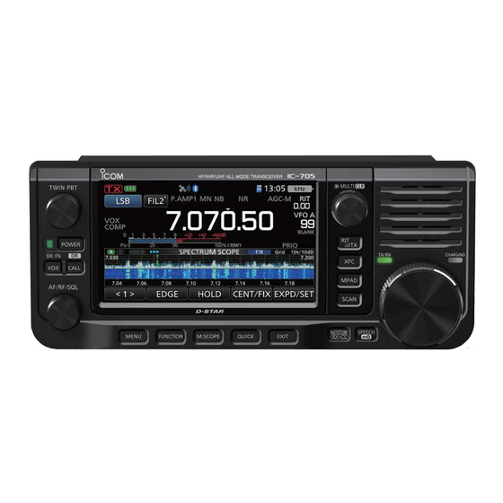
Icom IC-705 Advanced Manual
Hf/vhf/uhf all mode transceiver
Hide thumbs
Also See for IC-705:
- Basic manual (97 pages) ,
- Reference manual (29 pages) ,
- Installation manual (8 pages)
Table of Contents
Advertisement
Quick Links
ADVANCED MANUAL
HF/VHF/UHF ALL MODE
TRANSCEIVER
|705
This manual describes instructions for advanced features and
instructions.
See the BASIC MANUAL that come with the transceiver for
precautions and basic operations.
INTRODUCTION
1 BATTERY CHARGING
2 ADVANCED OPERATIONS
3 SCOPE OPERATION (ADVANCED)
4 microSD CARD (ADVANCED)
5 VOICE RECORDER FUNCTIONS
6 VOICE TX MEMORY FUNCTION
7 MEMORY OPERATION
8 SCANS
9 OTHER FUNCTIONS
10 Bluetooth
®
OPERATION
11 WIRELESS LAN OPERATION
12 GPS OPERATION (ADVANCED)
13 D-STAR OPERATION (BASIC)
14 D-STAR OPERATION (ADVANCED)
15 ABOUT THE DV GATEWAY FUNCTION
16 MAINTENANCE (ADVANCED)
17 UPDATING THE FIRMWARE
18 ADVANCED CONNECTIONS
Advertisement
Table of Contents
Troubleshooting

Related Manuals for Icom IC-705


Summary of Contents for Icom IC-705
- Page 1 ADVANCED MANUAL HF/VHF/UHF ALL MODE INTRODUCTION TRANSCEIVER |705 1 BATTERY CHARGING 2 ADVANCED OPERATIONS 3 SCOPE OPERATION (ADVANCED) 4 microSD CARD (ADVANCED) 5 VOICE RECORDER FUNCTIONS 6 VOICE TX MEMORY FUNCTION 7 MEMORY OPERATION 8 SCANS 9 OTHER FUNCTIONS 10 Bluetooth ®...
-
Page 2: About The Manuals
Thank you for choosing this Icom product. This product is designed and built with Icom’ s state of the art technology and craftsmanship. With proper care, this product should provide you with years of trouble- free operation. This product combines traditional analog technologies with the new digital technology, Digital Smart Technologies for Amateur Radio (D-STAR), for a balanced package. -
Page 3: Table Of Contents
TABLE OF CONTENTS ..........i Weather channel operation ABOUT THE MANUALS TRADEMARKS ............i (USA version only) ........2-19 Functions and features of Adobe ® Acrobat ® Reader ® . vi D Selecting a Weather channel ...... 2-19 D Weather alert function ......... 2-19 1 BATTERY CHARGING ������������������������������... - Page 4 SCAN screen ..........8-2 D AF Output ............ 10-3 D Headset Function Select ......10-3 SCAN SET screen ........8-3 D About the Icom headset ......10-4 Programmed scan and Fine Programmed Pairing with an Android™ device ..... 10-5 scan ............8-4 Disconnecting a Bluetooth ®...
- Page 5 TABLE OF CONTENTS Checking your location ......12-2 About the DR function ......13-2 D Displaying Position Data ......12-2 Ways to Communicate D GPS POSITION screens with the DR function ......... 13-2 and their meanings ........12-3 Enter your call sign (MY) D About the RX screen ........
- Page 6 TABLE OF CONTENTS Setting up a network ........ 15-4 D Adjusting the EMR AF level ....... 14-15 D When connecting your device Automatic DV detection ......14-16 to the Internet using a router ....... 15-6 Automatic Reply function ....... 14-17 D When connecting your device D Recording an Auto Reply message ...
- Page 7 FUNCTIONS AND FEATURES OF ADOBE ® ACROBAT ® READER ® The following functions and features can be used with Adobe ® Acrobat ® Reader ® • Keyword search • Find screen Click “Find (Ctrl+F)” or “Advanced Search (Shift+Ctrl+F)” in the Edit menu to open the search screen.
-
Page 8: Battery Charging
1� BATTERY CHARGING Battery information Charging the battery pack DBattery life NOTE: Prior to using the transceiver for the first time, the battery pack must be fully charged for After the charging is completed, the battery life optimum life and operation. will be approximately 3 hours when: LTo charge the battery pack while the transceiver is •... -
Page 9: Dcharging With A Usb Cable
• Confirm that the transceiver is OFF before connecting the DC power cable. • You cannot connect the optional cigarette lighter cable (CP-22 and CP-23L) to the IC-705’s [DC 13.8 V] jack. • If the applied voltage from the connected power source decreases, the battery pack is not charged, and the battery pack is used as a power source while transmitting. -
Page 10: Dcharging With The Optional Rapid Charger
R DANGER! NEVER use a battery pack that is not LThe charging indicator lights orange while charging, manufactured or approved by Icom. and lights green when charging is completed. • The BC-202IP2 rapid charger can only charge... -
Page 11: Specifications For The Battery Charger And Battery Pack
Specifications for the battery charger and battery pack DBC-202IP2 rapid charger (optional) • Power source requirement: 12 V ~ 16 V DC or the specified Icom power adapter (BC-123S) • Charging temperature range: 10°C ~ 40°C, 50°F ~ 104°F • Weight (approximate): 105 g, 3.7 oz... -
Page 12: Advanced Operations
2� ADVANCED OPERATIONS VOX function VOX GAIN SSB, AM, FM, and DV modes (Default: 50%) The Voice-Operated Transmission (VOX) Adjusts the transmit/receive switching threshold function switches between transmit and receive level to between 0% and 100% for VOX with your voice. This function enables hands-free operation. -
Page 13: Tx Function
ADVANCED OPERATIONS Operating CW (ADVANCED) ∂TX function The ∂TX function shifts your transmit frequency DAbout the CW Reverse mode up to ±9.99 kHz without shifting the displayed The CW-R (CW Reverse) mode reverses the frequency. receive Beat Frequency Oscillator (BFO) to receive CW signals. -
Page 14: Dusing The Memory Keyer Function (Keyer)
Contents memory • The touched memory contents are sent. 4. To repeatedly send the memory contents, CQ TEST CQ TEST DE ICOM ICOM TEST touch the Memory Keyer key for 1 second. UR 5NN 001 BK Repeat icon CFM TU QRZ? L“001”... -
Page 15: Dkeyer Memory Edit Menu (Edit)
ADVANCED OPERATIONS Operating CW (ADVANCED) DKeyer memory edit menu (EDIT) You can edit the Keyer memory contents. 5. Enter “QSL TU DE JA3YUA TEST,” and then LYou can use up to a total of 8 Memory Keyers (M1 touch [ENT] to save. to M8), and you can enter up to 70 characters in each memory. -
Page 16: Dcontest Number Menu (001 Set)
ADVANCED OPERATIONS Operating CW (ADVANCED) DContest number menu (001 SET) Number Style You can set the number style, Count-up trigger, (Default: Normal) and preset number. Sets the numbering system used for contest (serial) numbers— normal or short morse 1. Display the KEYER 001 screen in the CW numbers. -
Page 17: Dkeyer Set Menu (Cw-Key Set)
ADVANCED OPERATIONS Operating CW (ADVANCED) DKeyer Set menu (CW-KEY SET) Dot/Dash Ratio In this screen, you can set the memory keyer (Default: 1:1:3.0) repeat time, dash weight, paddle specifications, Sets the dot/dash ratio. key type, and so on. • Set to between 1:1:2.8 ~ 1:1:4.5 in 0.1 steps. 1. -
Page 18: Operating Rtty (Fsk)
ADVANCED OPERATIONS Operating RTTY (FSK) The IC-705 has a built-in RTTY decoder and DRTTY decoding encoder. Using contents set in the RTTY TX Rotate to tune a signal. memory, you can do basic RTTY operations without using an external device or software. -
Page 19: Dtransmitting An Rtty Memory Content
1. Display the RTTY DECODE screen in the RTTY mode. ↵ 73 GL SK ↵ » DECODE ↵ CQ CQ CQ DE ICOM ICOM ICOM K ↵ ↵ MY TRANSCEIVER IS IC–705 & 2. Touch [TX MEM]. ANTENNA IS A TRIBAND WHIP. ↵... -
Page 20: Dediting An Rtty Memory
ADVANCED OPERATIONS Operating RTTY (FSK) DEditing an RTTY memory You can edit the characters in the RTTY 7. Enter new characters, and then touch [ENT] memories. You can save and transmit 8 RTTY to save. memories (RT1 ~ RT8) for often-used RTTY messages. -
Page 21: Dturning On The Rtty Log
ADVANCED OPERATIONS Operating RTTY (FSK) DTurning ON the RTTY log DViewing the RTTY log contents Turn ON the RTTY log to save your TX and RX You can view the saved RTTY log contents. RTTY operating record onto a microSD card. LYou can select the data format type in “Log Set”... -
Page 22: Drtty Decode Log Set Screen
ADVANCED OPERATIONS Operating RTTY (FSK) DRTTY DECODE LOG SET screen File Type In this screen, you can set the log file type, time (Default: Text) stamp setting, and other RTTY settings. Selects the file type to save a log onto a microSD card from Text and HTML. -
Page 23: Drtty Decode Set Screen
ADVANCED OPERATIONS Operating RTTY (FSK) DRTTY DECODE SET screen FFT Scope Averaging In this screen, you can set the FFT scope setting, (Default: OFF) USOS function, and so on. Sets the FFT scope waveform averaging function to between 2 and 4, or OFF. 1. -
Page 24: Tone Squelch Operation
ADVANCED OPERATIONS Tone squelch operation About the Tone squelch types indication FM mode The Tone squelch opens only when you receive TSQL: Tone Squelch function a signal that includes a matching subaudible tone DTCS(T)/TSQL(R) (“D” in “D-TSQL” blinks): in the FM mode. You can silently wait for calls DTCS code in TX, Tone squelch in RX from other stations using the same tone. -
Page 25: Dtcs Code Squelch Operation
ADVANCED OPERATIONS DTCS code squelch operation About the DTCS code types indication FM mode The Tone squelch opens only when you receive DTCS: DTCS Code function a signal that includes a matching DTCS code in DTCS(T) (“DTCS” blinks): the FM mode. You can silently wait for calls from DTCS code in TX, Tone off in RX other stations using the same tone. -
Page 26: Repeater Operation
ADVANCED OPERATIONS Repeater operation A repeater receives your transceiver’s signals DChecking the repeater input signal and simultaneously retransmits them on You can check whether or not you can directly a different frequency to provide a greater receive another station’s transmit signal, by communication range. -
Page 27: Dsetting The Repeater Tone Frequency
“T-CALL” to the Custom key on the optional Bluetooth headset. » SET > Bluetooth Set > Headset Set > Icom Headset > Custom Key 2. Set the operating mode to “FM.” 3. While holding down [PTT] to transmit, push the key that “T-CALL”... -
Page 28: Duplex Operation
ADVANCED OPERATIONS Duplex operation Data communication The Duplex operation shifts the transmit SSB-DATA, AM-DATA, and FM-DATA modes frequency up or down from the receive frequency You can operate the data mode using AFSK by an offset amount. (Audio Frequency Shift Keying). LWhen operating PSK31, SSTV, or JT65B with a PC application software, refer to the software’s •... -
Page 29: About The 5 Mhz Frequency Band Operation (Usa Version Only)
ADVANCED OPERATIONS About the 5 MHz frequency band operation (USA version only) Operation on the 5 MHz frequency band is For the USB and USB data modes: allowed on 5 discrete frequencies, and you must The FCC specifies center frequencies on the adhere to the following: 5 MHz frequency band. -
Page 30: Weather Channel Operation (Usa Version Only)
ADVANCED OPERATIONS Weather channel operation (USA version only) There are 10 weather channels for monitoring DWeather alert function the National Oceanographic and Atmospheric NOAA broadcast stations transmit weather alert Administration (NOAA) weather broadcasts. tones before important weather announcements. When the weather alert function is turned ON, the selected weather channel is monitored every DSelecting a Weather channel 5 seconds for an announcement. -
Page 31: Scope Operation (Advanced)
3� SCOPE OPERATION (ADVANCED) Spectrum Scope screen DAdjusting the sweep speed DAdjusting the Reference level Select the sweep speed to change the FFT When monitoring a weak signal that is buried in scope refresh speed and the waterfall speed. the noise floor, or monitoring a strong signal but LTo change only the waterfall speed, select “Slow,”... -
Page 32: Scope Set Screen
SCOPE OPERATION (ADVANCED) SCOPE SET screen CENTER Type Display This screen is used to set the waveform color, (Default: Filter Center) Scope range for the Fixed mode, and so on. Selects the center frequency of the SPECTRUM SCOPE screen. (Only in the Center mode) 1. - Page 33 SCOPE OPERATION (ADVANCED) SCOPE SET screen Waveform Type Waterfall Speed (Default: Fill) (Default: Mid) Selects the outline waveform display for the FFT Selects the Waterfall speed. scope screen. • Slow: Sets the Waterfall speed to Slow. • Fill: Displays only the waveform, in color. •...
- Page 34 SCOPE OPERATION (ADVANCED) SCOPE SET screen Fixed Edges 11�00 – 15�00 (Default: No.1 14.000–14.350 MHz) (Default: No.2 14.000–14.100 MHz) 0�03 – 1�60 (Default: No.1 0.500–1.500 MHz) (Default: No.3 14.100–14.350 MHz) (Default: No.2 0.500–1.500 MHz) • Settable range: 11.000 ~ 15.000 MHz (Default: No.3 0.500–1.500 MHz) Sets the Upper and Lower Edge frequencies in the Fixed mode.
- Page 35 SCOPE OPERATION (ADVANCED) SCOPE SET screen 108�00 – 137�00 (Default: No.1 118.000–119.000 MHz) (Default: No.2 126.500–127.500 MHz) (Default: No.3 135.000–136.000 MHz) • Settable range: 108.000 ~ 137.000 MHz 137�00 – 200�00 (Default: No.1 144.000–144.500 MHz) (Default: No.2 146.020–147.020 MHz) (Default: No.3 145.800–146.000 MHz) •...
-
Page 36: Microsd Card (Advanced)
• After the loading ends, “COMPLETED! Restart LIf you want to load all the contents on the LOAD the IC-705.” is displayed. OPTION screen, touch “ALL” and go to step 6. LWhen you select “REF Adjust” in step 4, “The LIf you want to load only the repeater list, touch new “REF Adjust”... -
Page 37: Deleting A Data File
microSD CARD (ADVANCED) Deleting a data file Displaying the microSD card information Follow the steps below to delete the files you no longer need on the microSD card. You can display the microSD card capacity, and the time remaining for voice recording. NOTE: Deleted data from a card cannot be recalled. -
Page 38: Importing Or Exporting A Csv Format File
4. Touch the CSV file to import. 5. Touch [YES]. • After the importing ends, “COMPLETED! Restart the IC-705.” is displayed. 6. Turn OFF the transceiver power, then turn it ON again to restart the transceiver. TIP: To import a repeater list, see page 13-15 for... -
Page 39: Dexporting
microSD CARD (ADVANCED) Importing or Exporting a CSV format file DExporting 1. Open the IMPORT/EXPORT screen. 6. Touch [YES]. » SET > SD Card > Import/Export 2. Touch “Export.” 7. To close the EXPORT screen, push several times. 3. Touch the data to export. (Example: Your Call Sign) 4. -
Page 40: About The Microsd Card's Folders
VoiceTx yyyymmdd • Voice folder • IC-705 folder The recorded QSO audio date folders. The folders created in the IC-705 are contained in • yyyymmdd folder this folder. The recorded audio file in the “wav” format. • Capture folder The folder name is automatically created in the The captured screen data in the “png”... -
Page 41: Voice Recorder Functions
5� VOICE RECORDER FUNCTIONS Recording a QSO audio This transceiver is equipped with a QSO recorder DQuick recording not only for the receive audio but also for the You can quickly record the received audio. transmit audio. This function is useful to make a QSO record, 1. -
Page 42: Playing Back A Qso Audio
VOICE RECORDER FUNCTIONS Playing back a QSO audio You can playback the recorded QSO audio. Action Plays the previous file. 1. Insert the microSD card in which the recorded L While the oldest file is playing back, audio is saved. pushing starts playing the beginning of the oldest file, even if there are other files... -
Page 43: Checking The Folder Or File Information
VOICE RECORDER FUNCTIONS Checking the folder or file information Checking the folder information You can check the folder information and recorded file information, that are listed below. 1. Open the PLAY FILES screen. » RECORD > Play Files Folder information 2. -
Page 44: Deleting Files
VOICE RECORDER FUNCTIONS Deleting files Deleting folders 1. Open the PLAY FILES screen. NOTE: All the files in the folder are also deleted. » RECORD > Play Files 1. Open the PLAY FILES screen. 2. Touch the folder where the file you want to »... -
Page 45: Recorder Set Screen
VOICE RECORDER FUNCTIONS RECORDER SET screen File Split You can change the recorder settings on this (Default: ON) screen. Turns the File Split function ON or OFF. • OFF: The audio is continuously recorded 1. Display the RECORDER SET screen. into the file, even if you switch between »... -
Page 46: Player Set Screen
VOICE RECORDER FUNCTIONS PLAYER SET screen Playing back audio on a PC You can fast forward or rewind while playing You can also playback the voice memory data on back. You can change the skip time in the a PC. PLAYER SET screen. -
Page 47: Voice Tx Memory Function
6� VOICE TX MEMORY FUNCTION Recording a Voice TX memory SSB, AM, FM, and DV modes 5. Touch to start recording. You can record up to 8 Voice transmit memories Adjust the Mic gain so that the “REC (T1 ~ T8) of up to one and a half minutes in each Level”... -
Page 48: Dplaying Back
VOICE TX MEMORY FUNCTION Entering a Voice TX memory name Recording a Voice TX memory You can assign a name to recorded Voice DPlaying back memories. 1. On the selected memory’s recording screen, touch to start playing back without Example: Entering “Contest” in Memory T1 transmitting. -
Page 49: Transmitting A Voice Memory Content
However, if then connecting an external keypad to [KEY] on the squelch is set to open, the transceiver repeatedly the IC-705. transmits after the repeat interval time expires, even » SET > Connectors > External Keypad signals are received. -
Page 50: Dadjusting The Output Level
VOICE TX MEMORY FUNCTION VOICE TX SET screen Transmitting a Voice memory content You can set the Automatic Monitor function and DAdjusting the output level the Transmit Repeat Interval on this screen. Adjust the Voice TX memory level. 1. Display the VOICE TX SET screen. 1. -
Page 51: Memory Operation
7� MEMORY OPERATION Memory channels Entering Memory channel contents The Memory mode enables you to quickly select NOTE: New content you enter will overwrite any often-used frequencies, modes, and other content already in the selected memory. parameters. While operating in the Memory mode, you can temporarily change the operating 1. -
Page 52: Selecting A Memory Channel
MEMORY OPERATION Selecting a Memory channel There are 3 ways to select a Memory channel. DSelecting on the MEMORY screen • Selecting with 1. Select the Memory mode. (Basic Manual) • Selecting on the MEMORY screen 2. Open the MEMORY GROUP screen. •... -
Page 53: Copying The Memory Channel Contents
MEMORY OPERATION Copying the Memory channel contents You can copy a Memory channel contents to the DCopying to another Memory channel VFO or to another Memory channel. 1. Select the Memory mode. (Basic Manual) 2. Assign the Select Memory Channel function . -
Page 54: Entering A Group/Memory Name
MEMORY OPERATION Entering a group/Memory name You can assign a name of up to 16 characters DEntering a Memory name to each channel group (00 ~ 99) and Memory 1. Open the MEMORY GROUP screen. channel. » MEMORY 2. Touch the channel group. (Example: 01) DEntering a group name 1. -
Page 55: Clearing A Memory Channel
MEMORY OPERATION Clearing a Memory channel MEMORY screen » MEMORY > Group 00 ~ 99, CALL CH You can clear a no-longer-used memory channel and reset it as a blank channel, except for the You can edit Memory channel contents on the Call channels (C1 and C2). -
Page 56: Memo Pad
MEMORY OPERATION Memo Pad There are 5 Memo Pads as the default to save DMEMO PAD screen frequencies and operating modes for easy writing The MEMO PAD screen displays the saved and recall. You can increase the Memo Pads to contents in a list, in which you can select or 10 in the following item. -
Page 57: Scans
8� SCANS Scan types Preparation DSquelch status VFO SCAN Used to detect a signal by automatically changing the The scan works with the selected band’s squelch frequency of the VFO mode. status. Be sure to adjust the squelch level Programmed scan (p. -
Page 58: Scan Screen
SCANS SCAN screen Display the SCAN screen. » SCAN VFO mode Memory mode Action Starts or cancels a Programmed Touch scan. PROG Touch for Displays the SCAN SELECT 1 second screen. Touch Starts or cancels a Memory scan. MEMO Touch for Displays the SCAN SELECT 1 second screen. -
Page 59: Scan Set Screen
SCANS SCAN SET screen Resume Timer 1. Display the SCAN screen. (Default: 2sec) » SCAN Selects the scan Resume Timer. When a received signal disappears, the scan resumes 2. Touch [SET]. after this set period of time passed. • 0sec: The scan resumes immediately after the signal disappears. -
Page 60: Programmed Scan And Fine Programmed Scan
SCANS Programmed scan and Fine Programmed scan DProgrammed scan operation Repeatedly scans the Program Scan Edge ranges. 1. Select the VFO mode. 2. Select the operating mode and tuning step. Scan (Example: USB, 1 kHz) 3. Display the SCAN screen. Jump »... -
Page 61: Entering Scan Edges
SCANS Entering Scan Edges You can enter the upper and lower frequency 8. Enter the upper and lower edge frequency, edges to the Program Scan Edge ranges for then touch [ENT]. Program scans. Each Program Scan Edge range Entry example: [1] [1] [8] [ENT] [1] [3] [6] [ENT] has its own name, mode, and IF filter settings. -
Page 62: Memory Scan
SCANS Memory scan DMemory scan operation Repeatedly scans all entered Memory channels (except C1 and C2). 1. Select the Memory mode. Blank (not entered) Memory channels are 2. Display the SCAN screen. skipped. » SCAN 3. Touch [MEMO] for 1 second. Ch 00 Ch 01 Ch 02... -
Page 63: Select Memory Scan
SCANS Select Memory scan DSelect Memory scan operation Repeatedly scans Select Memory channels (★1, ★2, ★3). 1. Select the Memory mode. 2. Display the SCAN screen. Ch 00 Ch 01 Ch 02 Ch 03 » SCAN “#1,” “#2,” and “#3” show that the channel 3. -
Page 64: Mode Select Scan
SCANS Mode Select scan DMode Select scan operation Repeatedly scans Memory channels (except C1 and C2) that are set to the mode selected 1. Select the Memory mode. before starting the scan. 2. Set the operating mode. 3. Display the SCAN screen. »... -
Page 65: F Scan And Fine ∂F Scan
SCANS ∂F scan and Fine ∂F scan D∂F scan operation Repeatedly scans within the ∂F span area. The scan starts from the center frequency. 1. Set the center frequency. 2. Set the operating mode and tuning step. 146.17 MHz 146.18 MHz 146.19 MHz (Example: FM, 1 kHz) Scan... -
Page 66: Temporary Skip Function
SCANS Temporary Skip function This function temporarily skips unwanted frequencies (or memory channels) during a scan for the set period of time or condition, without changing the Skip Channel setting. 1. Start a scan. • When a signal is detected, the scan pauses. 2. -
Page 67: Other Functions
» SET > Connectors > USB SEND/Keying Power down transmission Reduces the transmission output power. The IC-705 has two virtual COM ports, A and B. The transmit and receive control (USB SEND), TX inhibit CW Keying, or RTTY (FSK) Keying signals from Disables the transmitter. -
Page 68: Measuring Swr
OTHER FUNCTIONS Measuring SWR The transceiver has a high-performance SWR DSpot measurement meter. This meter displays a stable measurement 1. Turn OFF any connected antenna tuner. in real time, even if the transmit output power LPerform this step if an antenna tuner is varies frequently. -
Page 69: Dplot Measurement
OTHER FUNCTIONS Measuring SWR DPlot measurement You can measure the SWR over the entire set 6. Touch to start measuring. frequency range. • Displays the frequency marker “▲” and the measurement frequency. 1. Set the desired frequency band. NOTE: Before transmitting, monitor the 2. -
Page 70: Ntp Function
OTHER FUNCTIONS NTP function The Network Time Protocol (NTP) function DUsing the NTP function synchronizes the internal clock with a time By turning ON the NTP function, the transceiver management server. automatically synchronizes the internal clock with LTo use this function, an internet connection and the time management server. -
Page 71: Screen Capture Function
OTHER FUNCTIONS Screen Capture function You can capture the transceiver display onto DViewing the captured screen a microSD card. Most of the screens used in 1. Open the SCREEN CAPTURE VIEW screen. this manual are captured using this function. » SET > SD Card > Screen Capture View However, some displays cannot be captured. -
Page 72: Entering Dtmf Code
OTHER FUNCTIONS Entering DTMF code Transmitting the DTMF code The transceiver can save up to 16 memories of DTransmitting a DTMF code 24 digit DTMF code. 1. Display the DTMF screen. » DTMF 1. Display the DTMF screen. » DTMF 2. -
Page 73: Dselecting The Dtmf Transmit Speed
5. To close the DTMF SET screen, push Share Pictures function With this function, you can send a picture and view a received picture, even if you do not use the software application. LSee “About the Share Pictures function” that can be downloaded from the Icom website. -
Page 74: Setting The Opening Picture
(except the filename extension) Step 1� Saving a picture on the microSD card (PC) 1. Copy a picture file into the “IC-705” > “OpeningPicture” folder on the microSD card. LSee page 4-5 for detail. 2. Insert the microSD card into the transceiver. -
Page 75: Bluetooth ® Operations
® function You can connect Bluetooth devices to the transceiver, using the Bluetooth function. 1. Open the BLUETOOTH SET screen. » SET > Bluetooth Set Icom Headset 2. Touch “Bluetooth.” When you connect the VS-3 headset to Bluetooth ® the transceiver, you can wirelessly transmit and receive. -
Page 76: Connecting To A Bluetooth ® Headset
Step 2� Searching for the headset (Transceiver) 1. Open the PAIRING/CONNECT screen. » SET > Bluetooth Set > Pairing/Connect Displayed while connected Headset icon (“ICOM” indicates the Icom headset.) 2. Touch “Device Search.” TIP: How to automatically connect to the paired device When you turn ON the transceiver with 3. -
Page 77: Bluetooth ® Settings
10. Bluetooth ® OPERATION Bluetooth Settings ® DAF Output DHeadset Function Select You can select the AF Output device. You can select the PTT and microphone If “AF Output” is set to “Headset & Speaker,” you combination when either a Bluetooth headset or can hear audio from both a connected Bluetooth the transceiver microphone are used. -
Page 78: Dabout The Icom Headset
10. Bluetooth ® OPERATION Bluetooth Settings ® DAbout the Icom headset You can set the detailed settings of the optional VS-3 headset. Bluetooth ® Also, you can assign a key function to [PLAY], [FWD] [FWD], and [RWD] on the “Custom Key” screen. -
Page 79: Pairing With An Android™ Device
See page 14-37 about connecting to the • The Android device starts to send a pairing request. transceiver with an Android device using the • The Android device displays “To pair with: ICOM RS-MS1A application. BT(IC-705). Make sure it is showing this passkey: MMMMM.”... -
Page 80: Disconnecting A Bluetooth ® Device From The Transceiver
10. Bluetooth ® OPERATION Disconnecting a Bluetooth Deleting a Bluetooth device ® ® device from the transceiver from the pairing list There are 3 ways to disconnect a Bluetooth You can delete a Bluetooth device from the device (headset device or data device). pairing list. -
Page 81: Editing The Bluetooth ® Unit Name
3. Push 4. Touch “Edit Name.” 3. Touch [YES]. 5. Enter a name of up to 9 characters*, and then touch [ENT]. (Example: ICOM BT(IC-705)A) *After “ICOM BT.” • The transceiver will automatically restart. The maximum number of 6. To close the BLUETOOTH DEVICE... -
Page 82: Wireless Lan Operation
11� WIRELESS LAN OPERATION Wireless LAN operation Turning ON the Wireless LAN function You can use the Wireless LAN (WLAN) function for: • Synchronizing the internal clock with a time 1. Open the WLAN SET screen. management server. (p. 9-4) »... -
Page 83: Connecting To A Wireless Access Point (Ap)
11. WIRELESS LAN OPERATION Connecting to a Wireless Access Point (AP) 1. Open the ACCESS POINT screen. 6. To close the ACCESS POINT screen, push » SET > WLAN Set > Connection Settings several times. > Access Point LWhile connected to a wireless network, the wireless LAN icon is displayed. -
Page 84: Gps Operation (Advanced)
• Set the GSV sentence to OFF when sending the GPS message to conventional digital transceivers (IC-2820H, IC-E2820, ID-800H, IC- 91AD, IC-E91, IC-V82, IC-U82, IC-2200H). The GSV sentence is incompatible with them. They will not display GPS messages properly if sent as a GSV sentence from the IC-705. 12-1... -
Page 85: When A Received Signal Contains Position Data
12. GPS OPERATION (ADVANCED) When a received signal Checking your location contains position data You can check your current location. This section is described using received position When a received signal contains position data, data. the caller’s position data is displayed in the RX LThe screens are just examples. -
Page 86: Dgps Position Screens And Their Meanings
12. GPS OPERATION (ADVANCED) Checking your location DGPS POSITION screens and their meanings LInformation Example for the GPS POSITION screens: • Pushing to change the compass direction. GPS Memory: (p. 12-6) Tokyo Skytree • About the Course (p. 12-5) • About the Grid Locator (p. 12-5) Your station 251 mi Course: 0 degrees... -
Page 87: Dabout The Rx Screen
12. GPS OPERATION (ADVANCED) Checking your location DAbout the RX screen TX format: D-PRS Base station Moving symbol symbol For a mobile station, Course and For a base station, Output power, Antenna height, Speed are displayed. Antenna gain, and Antenna direction are displayed. Time that the caller sent the Object’s data. -
Page 88: Dabout The Course
12. GPS OPERATION (ADVANCED) Checking your location DAbout the Course DChanging the GPS Memory or Alarm The course displayed on the GPS POSITION You can change the GPS Memory or GPS Alarm screens is indicated in degrees. in the GPS POSITION screen. 0°... -
Page 89: Dchanging The Compass Direction
12. GPS OPERATION (ADVANCED) Checking your location DChanging the Compass Direction DSaving your own or a received station’s position You can set the compass direction to Heading Up, North Up, or South Up. You can save the position of your station or the position of the caller station. -
Page 90: Checking Gps Information (Sky View Screen)
12. GPS OPERATION (ADVANCED) Checking GPS information (Sky view screen) This screen is used to view GPS satellite information when the GPS icon does not stop blinking for a long time. The GPS Information displays the quantity, signal power, and position of the GPS satellites. The sky view screen displays the position of GPS satellites. -
Page 91: Transmitting D-Prs Data
12. GPS OPERATION (ADVANCED) Transmitting D-PRS data When D-PRS is selected as the GPS TX mode, NOTE: you can transmit D-PRS data. • If “GPS select” is set to “Manual,” the manually When operating in the D-PRS mode, the entered position data in “Manual Position” is following codes are transmitted to the PC. -
Page 92: Ddisplayed Items
12. GPS OPERATION (ADVANCED) Transmitting D-PRS data DDisplayed items Depending on the TX format, the setting items and displayed order of the items differ. D-PRS Position Object Item Unproto Address ✓ ✓ ✓ ✓ ✓ ✓ ✓ ✓ ✓ Comment ✓... -
Page 93: Dsetting D-Prs Position (Mobile/Base)
12. GPS OPERATION (ADVANCED) Transmitting D-PRS data DSetting D-PRS Position (Mobile/Base) Set to transmit as a D-PRS Position (Mobile/Base). LSee page 12-32 for details. 1� Setting the GPS TX Mode to D-PRS 8� Setting the Altitude » GPS > GPS TX Mode > D-PRS Set whether or not to transmit the altitude data acquired from the GPS receiver. -
Page 94: Dsetting D-Prs Object/Item
12. GPS OPERATION (ADVANCED) Transmitting D-PRS data DSetting D-PRS Object/Item Set to transmit as a D-PRS Object or Item. LSee page 12-35 for details. 1� Setting the GPS TX Mode to D-PRS 8� Entering the Position data » GPS > GPS TX Mode > D-PRS Enter the position data of an Object or Item. -
Page 95: Dsetting D-Prs Weather
12. GPS OPERATION (ADVANCED) Transmitting D-PRS data D Setting D-PRS Object/Item DSetting D-PRS Weather Set to transmit as a D-PRS Weather station. LSee page 12-39 for details. 10� Selecting the SSID 1� Setting the GPS TX Mode to D-PRS » GPS > GPS TX Mode > D-PRS To assist in identifying your station’s type, select the APRS ®... -
Page 96: Dweather Station Transmission
USB cable (User supplied) * Depending on the PC environment, the COM port number used by the IC-705 may be higher than 5. In that case, use an application that can set it to higher than 5. To the [microUSB] port... -
Page 97: Dabout The Weather Data Content
12. GPS OPERATION (ADVANCED) Transmitting D-PRS data DAbout the weather data content The weather data should be input according to the format (based on the APRS ® Weather Data), shown below. Example: 220/004 g005 t077 r000 p000 P000 h50 b09900 End code No�... -
Page 98: Ddisplaying Your Location Using Mapping Software
12. GPS OPERATION (ADVANCED) Transmitting D-PRS data DDisplaying your location using mapping software If you transmit to an I-GATE station, and then You can check it on the Internet! enter the call sign information on the Internet Smartphone map website, the selected symbol is displayed. Example: Check your location on the APRS.fi site. - Page 99 12. GPS OPERATION (ADVANCED) Transmitting D-PRS data TIP: D-PRS data content D-PRS data content are shown below. DPosition (Mobile) JA3YUA-A>API705,DSTAR*:/002338h3437.38N/13534.29E>090/002/A=000012IC-705 OP.SATOH (e.g.) DPosition (Base) JA3YUA-A>API705,DSTAR*:/002338h3437.38N/13534.29E-PHG5132OP.SATOH (e.g.) DObject JA3YUA-A>API705,DSTAR*:;HAM FESTA*012345z3437.38N\13534.29Eh2020.01.01 am10-pm4 (e.g.) DItem JA3YUA-A>API705,DSTAR*:)REPEATER!3454.00N/13536.00ErPHG5132439.39MH z DV RPT JP3YHH A (e.g.) DWeather JA3YUA-A>API705,DSTAR*:/012345z3454.00N/13536.00E_220/004g005t077r000p000P000h50b09900 (e.g.) !2 D ata Extension(PHG codes)
-
Page 100: Transmitting Nmea Data
12. GPS OPERATION (ADVANCED) Transmitting NMEA data Set a GPS sentence to transmit GPS data in the NOTE: DV mode. • Set “GSV Sentence” to “OFF” when sending the GPS message to conventional digital transceivers. DSetting the GPS data sentence (p. -
Page 101: Dsetting A Gps Message
12. GPS OPERATION (ADVANCED) GPS Automatic Transmission Transmitting NMEA data DSetting a GPS message NOTE: • Use the GPS Automatic Transmission function in Enter a GPS message to be transmitted with the only the Simplex mode. position data. • Using the function through a Repeater may interfere with other communications. -
Page 102: Gps Memory
You can add your own position, other station’s example. position, or any positions that are manually (No Group) entered. Icom Osaka HC A: ICOM You can save up to 300 GPS memories, and Icom America conveniently saved in up to 27 groups, from A ~ Z and “(No Group).”... - Page 103 12. GPS OPERATION (ADVANCED) GPS Memory D Adding a GPS Memory 5� Entering the GPS Memory latitude 7� Entering the GPS Memory altitude 1. Touch “LATITUDE.” 1. Touch “ALTITUDE.” 2. Touch a digit to enter. 2. Touch [+/-] to set to plus or minus. 3.
-
Page 104: Dentering The Gps Memory Group Name
12. GPS OPERATION (ADVANCED) GPS Memory D Adding a GPS Memory DEntering the GPS Memory group name You can enter a name for each GPS Memory 9� Writing the GPS Memory group. 1. Touch “<<Add Write>>.” 1. Open the GPS MEMORY screen. »... -
Page 105: Ddeleting Gps Memory
12. GPS OPERATION (ADVANCED) GPS Memory DDeleting GPS Memory You can delete the GPS Memories. TIP: Deleting a specific GPS Memory There are 2 ways to delete the Memories: You can delete a specific GPS Memory. • Deletes all GPS Memory in a group. 1. -
Page 106: Drearranging The Display Order Of The Gps Data
12. GPS OPERATION (ADVANCED) GPS Memory DRearranging the display order of the GPS data You can move the entered GPS Memories to rearrange their display order in the selected GPS Memory group. LTo move the GPS Memory out of their assigned Memory group, select the Memory group in the GPS MEMORY EDIT screen, and then save. -
Page 107: Gps Alarm
12. GPS OPERATION (ADVANCED) GPS Alarm The transceiver can sound a GPS Alarm when a target station or position comes into the alarm area. This function can be set to a caller station, all GPS Memories, a selected GPS Memory group, or a selected GPS Memory. -
Page 108: Dsetting The Gps Alarm Function To All Memories (All Gps Memories)
12. GPS OPERATION (ADVANCED) GPS Alarm DSetting the GPS Alarm function to All Memories (all GPS Memories) 1. Open the GPS ALARM screen. LInformation » GPS > GPS Alarm • When either one of the stations in the group enters the set range, the alarm sounds 3 times. -
Page 109: Dsetting The Gps Alarm Function To Rx (A Caller Station)
12. GPS OPERATION (ADVANCED) GPS Alarm DSetting the GPS Alarm function to RX (a caller station) 1. Open the GPS ALARM screen. LInformation » GPS > GPS Alarm • When a station with its GPS Alarm set enters within an approximate 1 kilometer (1094 yards) range, 2. -
Page 110: Gps Logger Function
12. GPS OPERATION (ADVANCED) GPS Logger function The GPS Logger function enables you to DConfirming the GPS Logger function save location data from a GPS receiver onto a Confirm the GPS Logger function is turned ON. microSD card as a log. When the GPS Logger function is ON, the The GPS Logger saves Latitude, Longitude, transceiver saves the location data from the GPS... -
Page 111: Dsetting The Gps Record Sentence
12. GPS OPERATION (ADVANCED) GPS Logger function DSetting the GPS record sentence Select the GPS sentence for the GPS Logger function. Select only the required sentences to reduce the data volume. See the contents table shown below before selecting. 1. Open the GPS LOGGER screen. »... -
Page 112: Dviewing The Log Data On A Pc Map
(yyyy: Year, mm: month, dd: day, hh: hour, mm: minute, ss: second). • Displays the “IC-705” folder. 6. Import the log file to a mapping software. 4. Double-click the “IC-705” folder. • You can see your route on the software map. - Page 113 12. GPS OPERATION (ADVANCED) GPS Logger function TIP: About the recorded NMEA sentence for GPS logging Regarding the GPS logging data of the IC-705, each sentence corresponds to the NMEA standard and is recorded in the following format. D GGA sentence (e.g.) $GPGGA,161229.487,3723.2475,N,12158.3416,W,1,07,1.0,9.0,M,25.5,M,3,0000*18<CR><LF>...
-
Page 114: Gps Set
12. GPS OPERATION (ADVANCED) GPS SET NOTE: The default settings shown below are for the USA transceiver version. The default settings may differ, depending on your transceiver version. To return to your transceiver version’s default settings, push and touch “Default.” Power Save (Default: Auto) »... - Page 115 12. GPS OPERATION (ADVANCED) GPS SET » GPS » GPS > GPS TX Mode > D-PRS > TX Format > Position GPS TX Mode (Default: OFF) Symbol (Default: Person) Selects a GPS transmission mode to send GPS Selects the symbol that indicates your operating position data while in the DV mode.
- Page 116 12. GPS OPERATION (ADVANCED) GPS SET SSID (Default: ---) Comment Selects an SSID based on APRS ® to add to Enter a comment to transmit it with the D-PRS your call sign, to show your operating style to position data. other stations.
- Page 117 12. GPS OPERATION (ADVANCED) GPS SET Altitude (Default: OFF) Height (Default: 10ft) Selects whether or not to transmit altitude data Selects the height of the base station’s antenna, with the position data in the D-PRS mode. to transmit along with the position data. LThe number of characters you can enter in LThis item is displayed when “Data Extension”...
- Page 118 12. GPS OPERATION (ADVANCED) GPS SET Position » GPS > GPS TX Mode > D-PRS (Default: LATITUDE: 0°00.00′N, > TX Format > Object LONGITUDE: 0°00.00′W, ALTITUDE: ------ft) Object Name Displays the position information of the Object. Enter an Object name of up to 9 characters. Push to open the QUICK MENU screen shown below.
- Page 119 12. GPS OPERATION (ADVANCED) GPS SET Data Extension (Default: OFF) Gain (Default: 0dB) Selects whether or not to transmit the Course/ Selects the gain of the Object’s antenna, to Speed data or the Power/Hight/Gain/Directivity transmit along with the position data. data with the position data in the D-PRS mode.
- Page 120 12. GPS OPERATION (ADVANCED) GPS SET Position » GPS > GPS TX Mode > D-PRS (Default: LATITUDE: 0°00.00′N, > TX Format > Item LONGITUDE: 0°00.00′W, ALTITUDE: ------ft) Item Name Displays the position information of the Item. Enter an Item name of up to 9 characters. Push to open the QUICK MENU screen shown below.
- Page 121 12. GPS OPERATION (ADVANCED) GPS SET Speed (Default: 0mph) SSID (Default: ---) Sets the Item’s speed to between 0 and Selects an SSID based on APRS ® to add to 1150 mph.* your call sign, to show your operating style to * If the Speed unit is set to “km/h,”...
- Page 122 12. GPS OPERATION (ADVANCED) GPS SET » GPS > GPS TX Mode > D-PRS > TX Format > Weather Symbol (Default: WX Station) The symbol is an icon that indicates the weather station’s means of transportation or location. The saved symbol is transmitted along with the position data while in the D-PRS mode.
- Page 123 12. GPS OPERATION (ADVANCED) GPS SET GPS Message » GPS > GPS TX Mode > NMEA Enter a GPS message of up to 20 alphanumeric GPS Sentence (Default: GGA) characters. (p. 12-18) Selects sentences to be transmitted in the GPS mode to transmit position data.
- Page 124 12. GPS OPERATION (ADVANCED) GPS SET RX screen (Received position data of the other station) » GPS Depending on the caller’s TX mode or TX format, the GPS Position displayed items and these meanings are different. The following lists describe the items for each category. Your current position, received position, or GPS No data is displayed when no position data is received Memory Alarm position information is displayed.
- Page 125 12. GPS OPERATION (ADVANCED) GPS SET » GPS GPS Position (continued) <3� When the caller’s TX format is D-PRS Position <4� When the caller’s TX format is D-PRS Object/ (Base station)> Item> Displays the caller’s direction from Displays the Object/Item’s direction Compass* Compass* your location.
- Page 126 12. GPS OPERATION (ADVANCED) GPS SET » GPS GPS Position (continued) <5� When the caller’s TX format is D-PRS Weather> MEM screen (GPS memory position) Displays the caller’s direction from Displays GPS Memory channel’s Compass* Compass* your location. direction from your location. Latitude Displays the caller’s latitude.
- Page 127 12. GPS OPERATION (ADVANCED) GPS SET » GPS » GPS > GPS Alarm GPS Memory Alarm Select (Default: OFF) The transceiver has 300 GPS memories to save Selects the target positions for the GPS Alarm the received position data, or often-used position function.
- Page 128 12. GPS OPERATION (ADVANCED) GPS SET » GPS > GPS Alarm » GPS > GPS Logger Alarm Area (RX/Memory) GPS Logger (Default: Both) (Default: ON) Selects the GPS active alarm range. Turns the GPS Logger function ON or OFF. When a target enters the active alarm range, This function logs the position, altitude, course, the GPS Alarm sounds, and the GPS alarm icon speed, and a number of satellites being used.
- Page 129 12. GPS OPERATION (ADVANCED) GPS SET » GPS GPS Auto TX (Default: OFF) Selects an option for the GPS automatic transmission function. This function automatically transmits the current position data received from a GPS receiver, as well as any entered GPS message, at the set interval.
-
Page 130: Star Operation (Basic)
13� D-STAR OPERATION (BASIC) Unique features of D-STAR • Easy Cross band operation through a • Easy call sign entry with the Repeater list repeater or TX/RX History • The Call Sign Capture key makes call sign capture easy! INTERNET INTERNET 430MHz 430MHz... -
Page 131: About The Dr Function
13. D-STAR OPERATION (BASIC) About the DR function You can easily use D-STAR repeaters with To display the DR screen, hold down the D-STAR Repeater (DR) function. With this 1 second. function, you can select the preset repeater or frequency in “FROM” (access repeater), and a Destination (Repeater/Station) target call sign in “TO”... -
Page 132: Enter Your Call Sign (My) Into The Transceiver
13. D-STAR OPERATION (BASIC) Enter your call sign (MY) into the transceiver Example: Enter “JA3YUA” as your own call sign To operate D-STAR, you must first enter your call sign into the MY call sign memory. You can enter into “1.” up to 6 MY call signs. -
Page 133: Register Your Call Sign At A Gateway Repeater
13. D-STAR OPERATION (BASIC) Register your call sign at a gateway repeater Step 2: Register your call sign To make a Gateway call through the Internet, you must register your call sign at a repeater that has 1. Follow the registration instructions found a gateway, usually one near you. -
Page 134: Making A Simplex Call
13. D-STAR OPERATION (BASIC) Making a Simplex call IMPORTANT! • The repeater list, described in this manual, may differ from your transceiver’s preloaded This section describes simplex operation contents. (through no repeater). • Although Japanese repeaters are used in NOTE: The frequencies may be different, the setting examples, the Japanese repeater depending on the transceiver’s version. -
Page 135: Accessing Repeaters
13. D-STAR OPERATION (BASIC) Accessing repeaters Step 2: Set “TO” (Destination) This section describes how to check whether or not you can access a local area repeater (Access 1. Touch “TO” twice. repeater), and if your signal is successfully sent to a destination repeater. -
Page 136: Receiving
13. D-STAR OPERATION (BASIC) Receiving Step 2: Save the destination call sign into Your When a DV call is received, the call signs of the caller, the called station, and the called station’s Call Sign memory from RX History access repeater are saved in the RX History. Up 1. -
Page 137: Capturing A Call Sign
13. D-STAR OPERATION (BASIC) Capturing a call sign Making a Local CQ call After you receive a signal, the calling station’s call You can make a Local CQ call when “TO” sign can be captured by holding down the Call Sign (Destination) is set to “Local CQ.”... -
Page 138: Making A Gateway Cq Call
13. D-STAR OPERATION (BASIC) Making a Gateway CQ call Calling an individual station You can make a Gateway CQ call when a destination You can make a call to an individual station when repeater is selected in “TO” (Destination). the station call sign is selected in “TO” (Destination). When you call an individual station through a What is a Gateway CQ Call? gateway, your call is automatically sent to the last... -
Page 139: Saving To Memory Channels
13. D-STAR OPERATION (BASIC) Saving to Memory channels Step 2: View the saved contents When “FROM” (Access repeater) and “TO” (Destination) settings are saved to a Memory 1. Hold down for 1 second to cancel the DR channel, the settings can be selected by rotating screen. -
Page 140: About Reflectors
13. D-STAR OPERATION (BASIC) About Reflectors DWhat is a reflector? DUnlinking a reflector A reflector is a special server connected to the Before trying to link to another reflector, BE Internet and running a version of the D-Plus SURE to unlink the reflector that is currently software. -
Page 141: Dlinking To A Reflector
13. D-STAR OPERATION (BASIC) About Reflectors Direct inputting a Reflector DLinking to a reflector TX History saves up to 5 reflectors that your If your repeater is not currently linked to a Access repeater linked to before. reflector, or if you want to change it to another reflector, follow the steps below. -
Page 142: Dusing A Reflector
13. D-STAR OPERATION (BASIC) About Reflectors DUsing a reflector DReflector Echo Testing 1. Touch “TO” to select, and then touch “TO” To confirm that your signal is correctly getting into again. the repeater, you can transmit a short message as a trial. After stopping transmission, your message will be played back. -
Page 143: Drequesting Repeater Information
13. D-STAR OPERATION (BASIC) About Reflectors DRequesting repeater information When you send the repeater information command, an ID message is sent back. 1. Touch “TO” to select, and then touch “TO” again. 2. Touch “Reflector.” 3. Touch “Repeater Information.” • Returns to the DR screen, and “Repeater Information”... -
Page 144: Updating The Repeater List
Insert the repeater list using a microSD card. card into the memory card slot or memory card You can download the repeater list from the Icom reader (user supplied) on your PC. website. LTo use the microSD card with the transceiver,... - Page 145 • After the importing ends, “COMPLETED! Restart the IC-705.” is displayed. 7. Turn the OFF transceiver power, then turn it ON again to restart the transceiver. TIP: If you copy the ICF file to the “Setting”...
-
Page 146: When Receiving No Reply
13. D-STAR OPERATION (BASIC) When receiving no reply To communicate through a repeater, your signal must access the repeater. The following chart is designed to help you correct problems which are not equipment malfunctions. Problem Possible Cause Solution REF� After your call, the repeater does A repeater settings are incorrect. -
Page 147: Star Operation (Advanced)
14� D-STAR OPERATION (ADVANCED) “FROM” (Access repeater) setting Your Access repeater must be set in “FROM” when you make a call on the DR screen. You have 5 ways to select the Access repeater. By rotating Select the preset repeater on the DR screen by touching “FROM” and then rotating Displayed while rotating When you know your access repeater:... -
Page 148: Dusing Your Transceiver's Repeater List
14. D-STAR OPERATION (ADVANCED) “FROM” (Access repeater) setting DUsing your transceiver’s repeater list When your access repeater is in your TIP: transceiver’s repeater list, you can select it from When you select an FM repeater: the list. By just selecting the repeater from the When an FM repeater is in your transceiver’s list, the repeater call sign, its frequency, duplex repeater list, you can select it from the list. -
Page 149: Dusing The Dr Scan
14. D-STAR OPERATION (ADVANCED) “FROM” (Access repeater) setting DUsing the DR scan Example: Selecting an active repeater using the The DR scan scans frequencies to find a signal on a repeater, or on a simplex frequency. DR scan. You can use 2 kinds of DR scans, Normal scan 1. -
Page 150: Dusing The Near Repeater Search Function
14. D-STAR OPERATION (ADVANCED) “FROM” (Access repeater) setting DUsing the Near Repeater Search function Step 2� Selecting the Access repeater from The transceiver searches for the nearest repeaters by using your location and the the Near Repeater list repeater’s entered position data. 1. -
Page 151: Dusing Tx History
14. D-STAR OPERATION (ADVANCED) “FROM” (Access repeater) setting DUsing TX History The TX History saves up to 10 of the latest TIP: When you touch the repeater for 1 second Access (From) repeaters you transmitted on. You in step 5, you can display the REPEATER can select a repeater from TX History as your DETAIL screen, or delete the repeater Access repeater. -
Page 152: To" (Destination) Setting
14. D-STAR OPERATION (ADVANCED) “TO” (Destination) setting “CQCQCQ,” a destination repeater, or a station TIP: After you receive the individual station or call sign must be set in “TO” when you make a repeater’s signal, the call sign can be captured call in the DV mode. -
Page 153: Dmaking A "Local Cq" (Local Area) Call
14. D-STAR OPERATION (ADVANCED) “TO” (Destination) setting DMaking a “Local CQ” (Local Area) call DUsing “Your Call Sign” When “Local CQ” is selected on the TO SELECT The “Your Call Sign” memory saves individual screen, “CQCQCQ” is set in “TO.” or repeater station call signs. -
Page 154: Dusing Rx History
14. D-STAR OPERATION (ADVANCED) “TO” (Destination) setting DUsing RX History DUsing TX History When a call is received in the DV mode, the call TX History saves the repeater and station name data is saved in the RX History. and call sign of up to 20 “TO” (Destination) Up to 50 callers, and only the last called call settings that were used when you made the calls. -
Page 155: Ddirectly Entering (Ur)
14. D-STAR OPERATION (ADVANCED) “TO” (Destination) setting DDirectly entering (UR) DDirectly entering (RPT) The destination station call sign can be directly The destination repeater call sign can be directly entered. entered. Example: Directly entering the call sign “JM1ZLK.” NOTE: BE SURE to include the node letter as the 8th digit. -
Page 156: Repeater Detail Screen
14. D-STAR OPERATION (ADVANCED) REPEATER DETAIL screen Depending on the content, such as position data The REPEATER DETAIL screen or UTC offset, the distance between your location and the repeater or the repeater time can be Repeater Call sign Repeater type displayed on the REPEATER DETAIL screen. -
Page 157: Message Operation
14. D-STAR OPERATION (ADVANCED) Message operation You can save up to 5 short messages in the DTransmitting a message transceiver’s memory to transmit in the DV mode. You can transmit a preset TX message by Each message can be up to 20 characters. pushing [PTT] in the DV mode. -
Page 158: Viewing Received Call Signs
14. D-STAR OPERATION (ADVANCED) Viewing received call signs When you receive a DV call, the calling station 3. Touch [DETAIL]. and the repeater call signs are saved. Up to 50 • Displays the RX history detail screen. • Rotate to select the page. calls can be saved. - Page 159 14. D-STAR OPERATION (ADVANCED) Viewing received call signs D View the call signs on the RX History screen <3rd page> • RX MESSAGE: Displays any message included TIP: “RX RPT1” setting may differ, depending in the received call, if entered. on the way the call was made.
-
Page 160: Bk Mode Communication
14. D-STAR OPERATION (ADVANCED) BK mode communication The Break-in (BK) function enables you to break into a conversation, where the 2 stations are communicating with call sign squelch (DSQL) enabled. LThe BK function is automatically turned OFF when you turn OFF the transceiver. LThis function can be used in the DV mode. -
Page 161: Emr Communication
14. D-STAR OPERATION (ADVANCED) EMR communication The Enhanced Monitor Request (EMR) DAdjusting the EMR AF level communication function can be used in only the The audio output level, when an EMR signal is DV mode. Using the EMR function, no call sign received, is adjustable between 0 and 100%. -
Page 162: Automatic Dv Detection
14. D-STAR OPERATION (ADVANCED) Automatic DV detection If you receive an FM signal while in the DV 1. Open the “DV Auto Detect” screen. mode, the “DV” and “FM” icons alternately blink » SET > DV SET > DV Auto Detect to indicate the received signal is FM. -
Page 163: Automatic Reply Function
14. D-STAR OPERATION (ADVANCED) Automatic Reply function Example: After receiving a call from “JM1ZLK,” When a call addressed to your own call sign is received, the Automatic Reply function sounds beeps sound and the transceiver beeps and automatically replies with your call automatically sends a reply call. -
Page 164: Drecording An Auto Reply Message
14. D-STAR OPERATION (ADVANCED) Automatic Reply function DRecording an Auto Reply message The “DV Auto Reply” screen You can record an Auto Reply message and save it on a microSD card to reply to the call with your Adjust the Mic gain so that the “REC Level”... -
Page 165: Dauto Position Reply Function
JA3YUA difficult to operate the transceiver, this function sounds beeps and automatically replies with your Destination (IC-705) own call sign and transmits your position data. Your station 1. You receive a call addressed to your own After receiving the Auto Position Reply call, the call sign. -
Page 166: Data Communication
* Depending on the PC environment, the COM port may automatically transmit it, depending on the number used by the IC-705 may be higher than 5. In software and the software settings. that case, use an application that can set it to higher than 5. -
Page 167: Ddv Fast Data Function
DDV Fast Data function To send data using the DV Fast Data function, follow the instructions below. LDV Fast Data communication can be made by only the following Icom transceivers: (As of July 2020) • IC-705 • IC-9700 • ID-31A/E PLUS •... -
Page 168: Digital Squelch Functions
14. D-STAR OPERATION (ADVANCED) Digital squelch functions The digital squelch opens only when you receive DThe Digital Code Squelch setting a signal addressed to your own call sign, or a 1. Push signal that includes a matching digital code. • Opens the FUNCTION screen. You can silently wait for calls from others. -
Page 169: Repeater List
PC using the CS-705 programming software. You can enter 4 types of frequencies into the • The repeater list can be downloaded from the repeater list, as shown below: Icom website. • DV Repeater https://www�icomjapan�com/support/ • DV Simplex • FM Repeater •... -
Page 170: Entering New Information Into The Repeater List
14. D-STAR OPERATION (ADVANCED) Entering new information into the repeater list This section describes how to manually enter new repeater information into the repeater list. The required setting items differ, depending on your communication usage. Confirm the required items, as shown below. NOTE: To enter repeater information into the repeater list, the repeater’s call sign must be entered first. -
Page 171: Dentering New Information Into The Repeater List
14. D-STAR OPERATION (ADVANCED) Entering new information into the repeater list DEntering new information into the repeater list Step 1� Selecting the repeater group Step 2� Selecting the communication type 1. Open the DV MEMORY screen. 1. Touch “TYPE.” » 2 > DV MEMORY 2. - Page 172 14. D-STAR OPERATION (ADVANCED) Entering new information into the repeater list D Entering new information into the repeater list Step 6� Entering the gateway repeater call sign Step 10� Selecting the Duplex direction LThis item is displayed when Step 2� Selecting the LWhen Step 2�...
- Page 173 14. D-STAR OPERATION (ADVANCED) Entering new information into the repeater list D Entering new information into the repeater list Step 13� Selecting the repeater tone frequency Step 17� Setting the UTC offset LWhen Step 2� Selecting the communication type LUniversal Time Coordinated (UTC) offset is the time is set to “DV Repeater”...
-
Page 174: Dediting Repeater Data
14. D-STAR OPERATION (ADVANCED) Entering new information into the repeater list DEditing repeater data You can edit repeater data. This is useful when already-entered data is incorrect, has changed, or some data needs to be added to the list. 1. Open the REPEATER GROUP screen. 7. -
Page 175: Ddeleting Repeater Data
14. D-STAR OPERATION (ADVANCED) Entering new information into the repeater list DDeleting repeater data 1. Open the REPEATER GROUP screen. NOTE: The currently selected repeater on the DR » 2 > DV MEMORY > Repeater List screen cannot be deleted. To delete the repeater, select another repeater on the DR screen. -
Page 176: Drearranging The Display Order Of The Repeaters
You can move the entered repeaters to rearrange 1. Open the RX HISTORY screen. their display order in the selected repeater group. » 2 > CD Example: Moving “Hirano/Icom” above “Nakano.” 2. Rotate to display the repeater you want to add to the repeater list. -
Page 177: Dskip Setting For The Dr Scan
14. D-STAR OPERATION (ADVANCED) Entering new information into the repeater list DSkip setting for the DR scan You can set repeaters as scan skip repeaters. The selected repeaters are skipped for faster scanning. You can set the skip setting to all repeaters in the selected repeater group, or to individual repeaters. LWhen a repeater is set as a skip repeater, its “USE (FROM)”... -
Page 178: Dentering Or Editing A Repeater Group Name
14. D-STAR OPERATION (ADVANCED) Entering new information into the repeater list DEntering or editing a repeater group name 1. Open the REPEATER GROUP screen. » 2 > DV MEMORY > Repeater List 2. Touch a repeater group that you edit the name for 1 second. -
Page 179: Your Call Sign
14. D-STAR OPERATION (ADVANCED) Your Call Sign 8. Touch “<<Add Write>>.” DEntering Your Call Sign You can manually enter a Your (destination) Call Sign. When a Your Call Sign is set to “TO,” you can make a call to the station, even if you do not know where the station is currently located. -
Page 180: Ddeleting Your Call Sign
14. D-STAR OPERATION (ADVANCED) Your Call Sign DDeleting Your Call Sign DRearranging the display order of Your Call Signs 1. Open the YOUR CALL SIGN screen. You can move Your Call Signs to rearrange » 2 > DV MEMORY > Your Call Sign their display order. -
Page 181: Manually Setting Call Signs
14. D-STAR OPERATION (ADVANCED) Manually setting Call Signs Step 2� Gateway “R2” setting Set or view the “UR,” “R1,” “R2,” and “MY” call signs to use in the DV mode. 1. Touch “R2.” » 2 > CS LTo manually enter a call sign, touch “R2” for 1 second, then touch “Edit.”... -
Page 182: Are Your Settings Correct
14. D-STAR OPERATION (ADVANCED) Are your settings correct? If you make a Local Area call with a gateway repeater still selected in “TO,” the destination repeater will be busy while you transmit. The stations that want to use the repeater as their Access repeater cannot access it, as shown below. -
Page 183: Using The Rs-Ms1A
OPC-2418 data cable (USB micro-B/USB Type-C) host function USB cable When using the Bluetooth function IC-705 • Android device Android 5.0 or later with the Bluetooth function. To a USB port To the [microUSB] port LConnect the USB micro-B connector (for the... -
Page 184: Dwhen Using The Bluetooth Function
14. D-STAR OPERATION (ADVANCED) Using the RS-MS1A DWhen using the Bluetooth function This section describes how to connect to the NOTE: If you cannot connect, check that transceiver from an Android device. the same CI-V address is set between the Before connecting, pair the transceiver with an transceiver and the RS-MS1A. -
Page 185: About The Dv Gateway Function
Global IP address assigned to your Windows or Android device. • When you use your Windows or Android device, read the RS-MS3W or RS-MS3A instruction manual in addition to this document. They can be downloaded from the Icom website. (pp. 15-12, 15-13) 15-1... -
Page 186: When Using The External Gateway Function
1. Open the “Gateway Select” screen. » 2 > DV GW > Gateway Select USB cable Other station 2. Touch “External Gateway (USB (B)).” INTERNET INTERNET IC-705 Windows or D-STAR Android device repeater Access Point mode Remote D-STAR transceiver* USB cable... -
Page 187: About The Terminal And Access Point (Ap) Call Sign
» 2 > DV GW > Internal Gateway Settings > Terminal/AP Call sign > Terminal/AP Call sign Other station Access Point Other station INTERNET INTERNET IC-705 INTERNET INTERNET D-STAR MY Call Sign: repeater IC-705 JA3YUA D-STAR MY Call Sign: Terminal/AP Call sign:... -
Page 188: Setting Up A Network
15. ABOUT THE DV GATEWAY FUNCTION Setting up a network Before using the DV Gateway function, you have NOTE: Depending on your contract, you may to set up a network. be charged a large or additional communication fee. Ask your Internet service provider about the content of your contract. - Page 189 • Depending on your Network environment, you may not be able to use this function. • The caller station must set “UDP Hole Punch” to “ON” in the IC-705 (When using the Internal Gateway function) or RS-MS3W/RS-MS3A (When using the External Gateway function) to use this function.
-
Page 190: Dwhen Connecting Your Device To The Internet Using A Router
15. ABOUT THE DV GATEWAY FUNCTION Setting up a network DWhen connecting your device to the Internet using a router The following items are needed to use the DV Gateway function. • An Internet connection with an IPv4 Global IP INTERNET INTERNET address... - Page 191 15. ABOUT THE DV GATEWAY FUNCTION Setting up a network D When connecting your device to the Internet using a router INTERNET INTERNET USB cable A static IP address to the transceiver, Windows, or USB cable Android device is recommended. Needs a Global IP address and forwarding port number 40000.
-
Page 192: Dwhen Connecting Your Device To The Internet Using A Cellular System
15. ABOUT THE DV GATEWAY FUNCTION Setting up a network DWhen connecting your device to the Internet using a cellular system A Global IP address is required to use the DV Gateway function. USB cable INTERNET INTERNET USB cable You can use a cellular system compatible computer. Needs a Global IP address. -
Page 193: Dwhen Connecting Your Device To The Internet Using A Mobile Router
15. ABOUT THE DV GATEWAY FUNCTION Setting up a network DWhen connecting your device to the Internet using a mobile router The following items are needed to use the DV Gateway function. • An Internet connection with an IPv4 Global IP address •... -
Page 194: Setting Up The Device
RS-RP3C installed. Ask the gateway repeater Router administrator for details. Mobile IC-705 router Terminal/AP Call sign Enter the Terminal/AP call sign that is registered as the access point on the RS-RP3C’s Personal Information screen. - Page 195 15. ABOUT THE DV GATEWAY FUNCTION Setting up the device D When using the Internal Gateway function Allowed Call Sign (Access Point Mode) (Default: Disable) Selects to use the call sign restriction for the Access Point mode. When “Enabled” is selected, this allows only stations with registered call signs to transmit through the Internet.
-
Page 196: Dwhen Using The Rs-Ms3W Software
The RS-MS3W is a Windows application to use COM port settings with the External Gateway function. Set the COM port. You can download it from the Icom website. 1. After connecting, turn ON the transceiver. 2. Click “Com Port (P)” in the “Settings (S).” System requirements •... -
Page 197: Dwhen Using The Rs-Ms3A
USB host function System requirements USB cable The following are required to use the RS-MS3A. IC-705 (As of July 2020) • Android device To a USB port To the [microUSB] port Android 5.0 or later with the USB host function... -
Page 198: Terminal Mode Operation
15. ABOUT THE DV GATEWAY FUNCTION Terminal mode operation DSetting the Terminal mode 1. Open the DV GATEWAY screen. TIP: Canceling the Terminal mode » 2 > DV GW Touch “<<Normal Mode>>” in the DV GATEWAY screen. 2. Touch “<<Terminal Mode>>.” »... -
Page 199: Doperating In The Terminal Mode
15. ABOUT THE DV GATEWAY FUNCTION Terminal mode operation DOperating in the Terminal mode NOTE: In the Terminal mode, you can make a Gateway CQ call, or a call to a specific station, using call sign routing. LYou cannot make a call if you select “Local CQ” or “Reflector.”... -
Page 200: Access Point Mode Operation
15. ABOUT THE DV GATEWAY FUNCTION Access Point mode operation DSetting the Access Point mode In this section, set an Access Point transceiver. TIP: Canceling the Access Point mode 1. Open the DV GATEWAY screen. Touch “<<Normal Mode>>” in the DV GATEWAY screen. -
Page 201: Dmaking A Gateway Call Through The Access Point Transceiver
15. ABOUT THE DV GATEWAY FUNCTION Access Point mode operation DMaking a Gateway call through the Access Point transceiver In this section, set up a Remote D-STAR transceiver you are going to operate. LRead the Remote D-STAR transceiver’s instruction manual for setting details. When using the DR function NOTE: While in the Access Point mode, you can make a Gateway CQ call or a call to an... - Page 202 15. ABOUT THE DV GATEWAY FUNCTION Access Point mode operation D Making a Gateway call through the Access Point transceiver When using the DR function Step 1. Register the Access Point information to Step 2� Set the Access Point using the DR the Repeater List (Continued) function 6.
- Page 203 15. ABOUT THE DV GATEWAY FUNCTION Access Point mode operation D Making a Gateway call through the Access Point transceiver When using the DR function In this document, the ID-51A (PLUS2)/ID-51E (PLUS2) is used as an example of a Remote D-STAR transceiver.
- Page 204 15. ABOUT THE DV GATEWAY FUNCTION Access Point mode operation D Making a Gateway call through the Access Point transceiver When using the DR function (Continued) Step 5� Set the frequency offset Step 6� Set “UR” to the destination station call sign 1.
-
Page 205: Troubleshooting
If an error icon is displayed when using the Internal Gateway function, read the following chart. If you are unable to locate the cause of a problem or solve it through the use of this chart, contact your Icom Dealer or Service Center. -
Page 206: Dtroubleshooting For The Terminal Mode Operation
The following chart is designed to help you correct problems which are not equipment malfunctions. If you are unable to locate the cause of a problem or solve it through the use of this chart, contact your Icom Dealer or Service Center. Problem... - Page 207 15. ABOUT THE DV GATEWAY FUNCTION Troubleshooting D Troubleshooting for the Terminal mode operation Problem Possible Cause Solution REF� After your call, the repeater The repeater cannot connect to the Wait for a while, and try again. – replies ’RPT?’ and the access destination repeater.
-
Page 208: Dtroubleshooting For The Access Point Mode Operation
The following chart is designed to help you correct problems which are not equipment malfunctions. If you are unable to locate the cause of a problem or solve it through the use of this chart, contact your Icom Dealer or Service Center. Problem... - Page 209 15. ABOUT THE DV GATEWAY FUNCTION Troubleshooting D Troubleshooting for the Access Point mode operation Problem Possible Cause Solution REF� After your call, the repeater The Remote D-STAR transceiver’s Set the Remote transceiver’s call p. 13-3 replies “RX” or “RPT?” and the call sign has not been set in the sign in the transceiver.
-
Page 210: Derror Messages Of The Rs-Ms3W And The Rs-Ms3A
If an error message is displayed when clicking (touching) <Start> in the RS-MS3W or RS-MS3A, read the following chart. If you are unable to locate the cause of a problem or solve it through the use of this chart, contact your Icom Dealer or Service Center. Message Possible Cause Solution REF�... - Page 211 16� MAINTENANCE (ADVANCED) Cloning Step 2� Remove the microSD card from the The IC-705 has a data cloning capability. This function is useful when you want to copy all master transceiver, then insert it into of the settings and entered contents from one the sub transceiver�...
-
Page 212: Maintenance (Advanced)
LIf you want to load all the contents on the LOAD • After the loading ends, “COMPLETED! Restart OPTION screen, touch “ALL,” then go to step 6. the IC-705.” is displayed. LIf you want to load only the repeater list, touch LWhen you select “REF Adjust” in step 4, “The “Repeater List Only,”... -
Page 213: Touch Screen Calibration Function
16. MAINTENANCE (ADVANCED) Touch screen calibration function When the screen does not respond, or the TIP: When the touch screen is not accurate, transceiver does not work correctly after touching and you cannot access the OTHERS screen� the screen, the touched point and the detected Do the following steps to display the “Touch point may be different. -
Page 214: General
IC-705. Then copy the downloaded firmware data from The firmware version is displayed. your PC into the “IC-705” folder on the card. TIP: You can also check the firmware version on the VERSION screen. -
Page 215: Dpreparation
LThese instructions are based on Microsoft ® Windows ® 1. Click the “Firmware/Software” link. Click 2. Enter “IC-705” into the Search box, and then click [Search]. Click 1Enter • The file starts downloading. 2Click • The firmware and the firm utility are compressed in a “zip”... -
Page 216: Updating The Firmware
Icom distributor for repair. This type of repair is out of warranty, even if the transceiver warranty period is still valid. -
Page 217: Advanced Connections
RTTY using a USB cable. See the interface circuit diagram below for details. Refer to the software application’s instruction manual for setup details. ( Icom does not guarantee the performance of the application software, PC, network device, or network settings.) - Page 218 A7560-7EX 1-1-32 Kamiminami, Hirano-ku, Osaka 547-0003, Japan © 2020 Icom Inc. Jul. 2020...
Need help?
Do you have a question about the IC-705 and is the answer not in the manual?
Questions and answers