Icom IC-7000 Instruction Manual
Hf/vhf/uhf all mode transceiver
Hide thumbs
Also See for IC-7000:
- Service manual (93 pages) ,
- Manual (34 pages) ,
- Modification instruction (8 pages)
Table of Contents
Advertisement
Quick Links
Advertisement
Table of Contents
Troubleshooting

Related Manuals for Icom IC-7000


Summary of Contents for Icom IC-7000
- Page 1 INSTRUCTION MANUAL HF/VHF/UHF ALL MODE TRANSCEIVER i7000...
-
Page 2: Foreword
We want to take a cou- ple of moments of your time to thank you for making the IC-7000 your radio of choice, and hope you agree with Icom’s philosophy of “technology first.” Many hours of research and development went into the de- sign of your IC-7000. -
Page 3: Illustrations
ILLUSTRATIONS Front panel HM-151 SPCH TUNER /LOCK /CALL MODE GENE F-INP ⁄3 ⁄2 ⁄1 ⁄0 Mic element The front panel and HM-151’s panel descriptions are descrived between pages 1 to 4, and on page 9, respec- tively (see the Chapter 1 (Panel de- scription) for more details). -
Page 4: Table Of Contents
■ Front panel q AF GAIN CONTROL [AF] (inner control; p. 33) w RF GAIN CONTROL/SQUELCH CONTROL [RF/SQL] (outer control; p. 35) e POWER KEY [PWR] (p. 25) r FRONT PANEL LATCH (p. 16) t PASSBAND TUNING/M-ch/RIT CONTROLS [PBT/M-ch/RIT] (pgs. 75, 79, 88, 102, 106) y TWIN PBT (M-ch/RIT) INDICATOR (pgs. -
Page 5: Precautions
fier will be damaged. Use Icom microphones only (supplied or optional). Other manufacturer’s microphones have different pin assign- ments, and connection to the IC-7000 may damage the transceiver. Beat signals may be heard on some frequencies. These will occur as a result of circuit construction. - Page 6 TABLE OF CONTENTS IMPORTANT …………………………………………i-1 FOREWORD ………………………………………… i-1 EXPLICIT DEFINITIONS …………………………… i-1 SUPPLIED ACCESSORIES …………………………i-1 ILLUSTRATIONS ……………………………………i-2 ■ Front panel ……………………………………… i-3 ■ Microphone (HM-151) ………………………… i-3 PRECAUTIONS ………………………………………ii TABLE OF CONTENTS …………………………… iii 1 PANEL DESCRIPTION ………………… 1–14 ■ Front panel ………………………………………… 1 ■...
-
Page 7: Table Of Contents
4 Paddle Polarity ……………………………… 50 5 Keyer Type ………………………………… 50 6 MIC U/D Keyer (HM-103) ………………… 50 D Paddle operation from [MIC] connector ………………………… 50 ■ Operating RTTY (FSK) ………………………… 51 D Convenient functions for receive …………… 52 D RTTY reverse mode ………………………… 53 D Twin peak filter …………………………………... - Page 8 TABLE OF CONTENTS 8 MEMORY OPERATION ……………… 102–112 ■ Memory channels ……………………………… 102 ■ Memory channel selection …………………… 102 ■ Memory programming ………………………… 103 D Programming in VFO mode………………… 103 D Programming in memory mode …………… 104 ■ Memory channel list …………………………… 105 D Selecting a memory channel using the memory channel list………………...
- Page 9 16 Auto Repeater ……………………………… 132 17 Tuner (Auto Start) ………………………… 132 18 Tuner (PTT start) …………………………… 133 19 [TUNER] Switch …………………………… 133 20 VSEND Select ……………………………… 133 21 SPEECH level ……………………………… 133 22 SPEECH Language ……………………… 133 23 SPEECH Speed …………………………… 133 24 SPEECH S-Level …………………………...
-
Page 10: Rf/Sql] (Outer Control; P
PANEL DESCRIPTION ■ Front panel q AF GAIN CONTROL [AF( )] (inner control; p. 33) ➥ Rotate to vary the audio output level from the speaker or headphones. Audio output increases Audio outut decreases Push momentarily to enter the set mode menu. •... - Page 11 ✔ What is the PBT control? PBT electronically narrows the IF passband width to reject interference. This transceiver uses DSP to implement PBT. ➥ While M-ch/RIT is selected: ● Rotate the inner control to select a memory ● channel number (p. 102). ●...
-
Page 12: Manual Notch Key [Mnf/Adj] (P
PANEL DESCRIPTION !0 MANUAL NOTCH KEY [MNF/ADJ] (p. 83) ➥ Push momentarily to turn the manual notch func- tion ON and OFF in SSB, CW and AM modes. • “ ” appears on the display when the function is ac- tivated. -
Page 13: Noise Reduction Key [Nr/Lev] (P
!9 TUNING STEP KEY [TS] (pgs. 30–32) ➥ While in SSB/CW/RTTY modes, push momentar- ily to turn the programmable tuning step ON and OFF. While in AM/FM/WFM modes, push mo- mentarily to toggle the programmable tuning step and 1 MHz quick tuning step. •... -
Page 14: Multi-Function Keys
PANEL DESCRIPTION ■ Multi-function keys D Menu M-1 functions SPLIT OPERATION ➥ Push momentarily to toggle the split func- tion ON and OFF. (p. 91) • “ ” and transmit frequency appear when the split function is ON. ➥ Push and hold for 1 sec. to turn the quick split function ON. - Page 15 DURING FM/WFM OPERATIONS: VOX FUNCTION (p. 85) ➥ Push momentarily to toggle the VOX func- tion ON and OFF. • “ ” appears when the VOX function is ➥ Push and hold for 1 sec. to enter the VOX set mode. •...
-
Page 16: D Menu S-1 Functions
PANEL DESCRIPTION D Menu S-1 functions DURING SSB/AM OPERATION: DURING CW OPERATION: KEY MET DURING RTTY OPERATION: DURING FM/WFM OPERATIONS: VO (p. 95) Push to enter the voice recorder mode. • The voice TX/RX menu or voice root menu appears depending on the “VOICE 1st Menu”... -
Page 17: D Menu S-3 Functions
D Menu S-3 functions MEMORY WRITE (pgs. 103, 104) Push and hold for 1 sec. to store the dis- played VFO frequency and operating mode into the selected memory channel. MEMO PAD WRITE (p. 111) Push to store the displayed VFO fre- quency and operating mode into a memo pad. -
Page 18: N Filter Selection [Fil] (P
➥ Pushing the same key 2 or 3 times calls up other stacked frequencies in the band. (p. 28) • Icom’s triple band stacking register memorizes 3 fre- quencies in each band. ➥ After pushing [(F-INP)ENT], enter a numeric fre- quency, followed by pressing [(F-INP)ENT] again. -
Page 19: D Microphone Connector
D Microphone connector MICROPHONE CONNECTOR INFORMATION Rear panel view HM-151 q +8 V DC output w Frequency up/down e M8V SW r PTT t GND (Microphone ground) y Microphone input u GND i DATA IN HM-103 q +8 V DC output w Frequency up/down e M8V SW r PTT... -
Page 20: Rear Panel
(p. 144) ➥ Designed for use with a personal computer for re- mote control of the transceiver functions. ➥ Used for transceiver operation with another Icom CI-V transceiver or receiver. y TUNER CONTROL SOCKET [TUNER] (p. 20) Accepts the control cable from an optional AH-4... -
Page 21: D Data Socket
D DATA socket DATA PIN No. NAME DATA IN Input terminal for data transmit. (1200 bps: AFSK/9600 bps: G3RUH, GMSK) Common ground for DATA IN, DATA OUT and AF OUT. PTT terminal for packet operation. Connect to ground to activate the transmitter. PTT P When grounded, microphone input (pin 6) of [MIC] connector will be disconnected. -
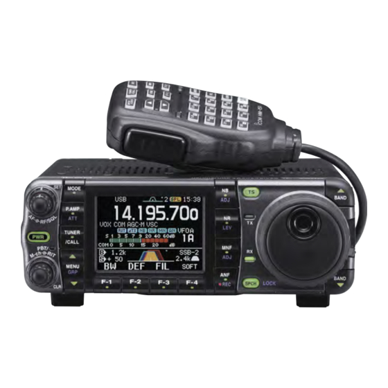
Page 22: Function Display
PANEL DESCRIPTION • When connecting the ACC conversion cable (OPC-599) Connect to ACC socket 9 10 11 12 ■ Function display q FREQUENCY READOUT Shows the operating frequency. w METER READOUTS ➥ Shows received signal strength while receiving. ➥ Shows either transmit power meter (Po), SWR, ALC or compression level meter (COM) while transmitting. - Page 23 !1 SPLIT INDICATOR Appears during split opeation. !2 IF FILTER INDICATOR (p. 77) Shows the selected IF filter number. !3 PASSBAND WIDTH INDICATOR (p. 77, 79) Graphically displays the passband width for twin PBT operation and center frequency for IF shift op- eration.
-
Page 24: Installation And Connections
In this case, an antenna tuner is used to match the transceiver and antenna. Low SWR allows full power for transmitting even when using the antenna tuner. The IC-7000 has an SWR meter to monitor the an- tenna SWR continuously. -
Page 25: Installation
■ Installation D Single body mounting Spring washer MB-62 (optional) Supplied with the MB-62* Flat washer *CAUTION: Non-supplied screws (longer than 8 mm) may damage the internal units. D Front panel separation q While pulling the front panel latch towards you, slide the front panel to the left (fig. -
Page 26: Required Connections
INSTALLATION AND CONNECTIONS ■ Required connections STRAIGHT KEY DATA 2 m/70 cm ANTENNA MICROPHONE (p. 10) HM-151 RTTY TERMINAL UNIT (p. 23) ANT2 ANT1 DC 13.8V DC POWER SUPPLY (p.19) AC outlet A DC power supply 13.8 V; at least 25 A Black GROUND (p. -
Page 27: Advanced Connections
■ Advanced connections DATA SOCKET (p. 12) 6-pin mini DIN socket to connect to a TNC, etc. for packet operation. VIDEO OUT to [VOUT] jack Vout 3.5(d) mm SOCKET (p. 12) DATA REMOTE (p. 144) Used for computer control and transceive operation. -
Page 28: Important
12 V battery IMPORTANT! Detailed installation notes for Icom mobile trans- ceivers to be fitted into vehicles are available. Con- tact your Icom dealer or distributor. Before connecting the DC power : positive + terminal : negative _ terminal... -
Page 29: External Antenna Tuners
[ACC] [ANT1] IC-7000 Ground • Turn the IC-7000’s power OFF when connecting the AT-180, otherwise, the CPU may malfunction and the AT-180 may not function properly. • The OPC-742 is required when using both the AT- 180 and a 2m/70cm linear amplifier. -
Page 30: Linear Amplifier Connections
OPC-599 conversion cable INPUT1 EXCITER 1&2 Ground : 230 V • The IC-7000 SEND relay is rated at 16 V and a 0.5 A DC. If these levels are exceeded, a larger external relay must be used. coaxial cable ALC (Blue) HSEND... -
Page 31: Connections For Cw
■ Connections for CW [KEY] Rear panel [ACC] For no break-in operation: Connect an external switch 9 10 11 such as a foot switch; or use the RTTY SEND terminal for 1 2 3 all bands. (See p. 23) [MICROPHONE] See p. -
Page 32: Connections For Rtty (Fsk)
INSTALLATION AND CONNECTIONS ■ Connections for RTTY (FSK) D When connecting to [ACC] socket Rear panel [ACC] [RTTY] Rear panel view 9 10 11 1 2 3 D When connecting to [MIC] connector [ACC] [MIC] 9 10 11 1 2 3 Rear panel view !2 AF out (light blue) -
Page 33: Installation And Connections
■ Connections for packet D When connecting to [DATA] socket DATA IN PTTP AF OUT [DATA] (Rear panel) D When connecting to [ACC] socket Rear panel [ACC] Rear panel view SQL* (light green) AF in (pink) AF out (light blue) 9 10 11 MSEND (orange) GND (red) -
Page 34: Basic Operation
BASIC OPERATION ■ When first applying power (CPU resetting) Before first applying power, make sure all connec- tions required for your system are complete by refer- ring to Chapter 2. Then, reset the transceiver using the following procedure. Resetting CLEARS all programmed contents in memory channels and returns programmed values in set mode. -
Page 35: Vfo Description
The IC-7000 VFO is somewhat different. The VFO dis- play of the IC-7000 acts like a computer’s window and can show one frequency and one operating mode. You can call up a desired frequency to the VFO with the memo pad-read key (p. -
Page 36: Vfo Operation
BASIC OPERATION ■ VFO operation D Selecting VFO A/VFO B q Select M-1. Menu group selection Push [MENU/GRP] for 1 sec. Selection from: M , S or G (Graphic) Menu selection (Example: M) Push [MENU/GRP] momentarily. Selection from: M - 1 , M - 2 or M - 3 w Push [F-2 A/B] to toggle VFO A or VFO B. -
Page 37: Selecting An Operating Band
■ Selecting an operating band HM-151 SPCH TUNER /LOCK /CALL MODE GENE F-INP BAND REGISTER 1 1.8 MHz 1.900000 MHz CW 3.5 MHz 3.550000 MHz LSB 7 MHz 7.050000 MHz LSB 10 MHz 10.120000 MHz CW 14 MHz 14.100000 MHz USB 18 MHz 18.100000 MHz USB 21 MHz... -
Page 38: Frequency Setting
BASIC OPERATION ■ Frequency setting The transceiver has several tuning methods for conve- nient frequency tuning. D Tuning with the main dial HM-151 SPCH TUNER /LOCK /CALL MODE GENE F-INP D Direct frequency entry with the microphone’s keypad The HM-151 has a keypad for direct frequency entry as described right. -
Page 39: D Programmable Tuning Step
D Programmable tuning step The operating frequency can be changed in steps of (0.01 (AM/FM/WFM only), 0.1, 1, 5, 9, 10, 12.5, 20 25 or 100 kHz selectable) for quick tuning. [TS] [DIAL] Appears D Selecting “kHz” step Programmable tuning steps are available to suit your operating requirements. -
Page 40: D Selecting 1 Hz Or 10 Hz Step (Ssb/Cw/Rtty Only)
BASIC OPERATION D Selecting 1 Hz or 10 Hz step (SSB/CW/RTTY only) When neither the quick tuning step or programmable ” appear, rotating [DIAL] changes the tuning step “ frequency in increments of 1 or 10 Hz. These tuning steps are only available in SSB, CW and RTTY modes. -
Page 41: Tuning Function (Cw/Rtty Only)
• [TS] switch flow chart SSB/CW/RTTY modes 10 Hz tuning momentarily 1 sec. Push 1 sec. 1 Hz tuning Appears ⁄ tuning function (CW/RTTY only) While operating in CW/RTTY, the ⁄ available for critical tuning. Dial sensitivity is reduced ⁄ of normal when the ⁄... -
Page 42: D Auto Tuning Step Function
BASIC OPERATION D Auto tuning step function When rotating the tuning dial rapidly, the tuning speed accelerates automatically as selected. q Push [AF( )] momentarily to enter the set mode menu. w Push [F-4 OTH] to enter the miscellaneous (oth- ers) set mode. -
Page 43: Operating Mode Selection
■ Operating mode selection The following modes are available in the IC-7000: SSB (LSB/USB), CW, CW-R (CW reverse), RTTY, RTTY-R (RTTY reverse), AM, FM and WFM (receive only). To select the desired mode of operation, push [MODE] one or more times, then push [MODE] for 1 sec., if necessary. -
Page 44: Squelch And Receive (Rf) Sensitivity
BASIC OPERATION ■ Squelch and receive (RF) sensitivity Adjusts the RF gain and squelch threshold level. The squelch removes noise output from the speaker (closed position) when no signal is received. • The squelch is particularly effective for FM. It is also avail- able for other modes. -
Page 45: Meter Function
■ Meter function The transceiver has 4 transmit meter functions for your convenience. Select the desired meter with the [F-3 MET] in the S-1 display. [MENU/GRP] [F-3] q Select S-1. • Push and hold [MENU/GRP] for 1 sec. once or twice to select the menu group S. -
Page 46: Lock Functions
BASIC OPERATION ■ Lock functions The lock function can only be activated when display- ing frequency, not in set mode, memory channel list- ing, or TV display. D Dial lock function The dial lock function prevents accidental change caused by [DIAL]. ➥... -
Page 47: Basic Operation
D Setting output power q Push [AF( )] momentarily to enter the set mode menu. w Push [F-1 QS] to enter the quick set mode. e Push [F-1 Y] or [F-2 Z] to select “RF Power.” r Rotate [DIAL] to set the desired output setting. •... -
Page 48: Receive And Transmit
RECEIVE AND TRANSMIT ■ Operating SSB q Push [ )]/[ )] to select the desired BAND BAND band or push a band key on the HM-151. w Push [MODE] momentarily or push and hold for 1 sec. to select LSB or USB mode. •... -
Page 49: D Convenient Functions For Transmit
filter settings into the memory channel for easy recall. *The channel center frequencies that are specified by the FCC, show the center frequency of their passband. However, the IC-7000 displays carrier point frequency, so set 1.5 kHz below from FCC channel center frequency. -
Page 50: Operating Cw
RECEIVE AND TRANSMIT ■ Operating CW q Connect a paddle or straight key as on page 22. w Push [Y( )]/[Z( BAND BAND band or push a band key on the HM-151. e Push [MODE] momentarily to select CW mode. •... -
Page 51: D Convenient Functions For Receive
D Convenient functions for receive • Preamp and attenuator (p. 74) ➥ Push [P.AMP/ATT] momentarily to turn the pre- amp ON or OFF. • “ ” appears when the preamp is set to ON. ➥ Push [P.AMP/ATT] for 1 sec. to turn the attenua- tor ON. -
Page 52: D Cw Reverse Mode
RECEIVE AND TRANSMIT D CW reverse mode The CW-R (CW Reverse) mode receives CW signals on the reverse sideband like that of LSB and USB modes. Use when interference is near the desired signal and you want to change the interference tone. q Push [MODE] several times to select CW mode. -
Page 53: D Cw Pitch Control
D CW pitch control The received CW audio pitch and monitored CW audio pitch can be adjusted to suit your preferences (300 to 900 Hz) without changing the operating fre- quency. q When CW (CW-R) mode is selected, enter the quick set mode. -
Page 54: Electronic Cw Keyer
[F-2] [F-3] [F-4] ¡ Memory keyer send menu ¡Memory keyer root menu The IC-7000 has a number of convenient functions for the electronic keyer that can be accessed from the memory keyer menu. q Push [MODE] to select CW mode. -
Page 55: D Memory Keyer Send Menu
Menu group selection Push [MENU/GRP] for 1 sec. Selection from: M , S or G (Graphic) Menu selection (Example: S) Push [MENU/GRP] momentarily. Selection from: S - 1 , S - 2 or S - 3 D Memory keyer send menu Pre-set characters can be sent using the memory keyer send menu. -
Page 56: D Editing A Keyer Memory
[MENU/GRP] [F-2] [F-3] [F-4] Memory channel select Selected character • Pre-programmed contents Contents CQ TEST CQ TEST DE ICOM ICOM TEST UR 5NN✽ BK CFM TU QRZ? • Programming contents q Push [MODE] to select CW mode. w Select S-1. -
Page 57: D Contest Number Set Mode
D Contest number set mode This menu is used to set the contest (serial) number and incrementing trigger channel, etc. [MODE] [F-1] [MENU/GRP] [F-2] [F-3] [F-4] 1 Number Style This item sets the numbering system used for contest (serial) numbers— normal or cut numbers. 2 Count UP Trigger This selects which of the four memory channels will have the contest serial number exchange. -
Page 58: D Keyer Set Mode
RECEIVE AND TRANSMIT D Keyer set mode This set mode is used to set the memory keyer repeat time, dash weight, paddle specifications, keyer type, etc. [MODE] [F-1] [MENU/GRP] [F-2] [F-3] [F-4] 1 Keyer Repeat Time When sending CW using the repeat timer, this item sets the time between transmission. -
Page 59: Rise Time
D Keyer set mode (continued) 3 Rise Time This item sets the envelop time period which the out- put power becomes the set transmit power. • About rise time Key action Tx output power Rise time 4 Paddle Polarity This item sets the paddle polarity. 5 Keyer Type This item selects the keyer type for [KEY] connector on the rear panel. -
Page 60: Operating Rtty (Fsk)
RECEIVE AND TRANSMIT ■ Operating RTTY (FSK) When using your RTTY terminal or TNC, consult the manual that comes with the RTTY terminal or TNC. q Push [Y( )]/[Z( BAND BAND band or push a band key on the HM-151. w Push [MODE] momentarily to select RTTY mode. -
Page 61: D Convenient Functions For Receive
D Convenient functions for receive • Preamp and attenuator (p. 74) ➥ Push [P.AMP/ATT] momentarily to turn the pre- amp ON or OFF. • “ ” appears when the preamp is set to ON. ➥ Push [P.AMP/ATT] for 1 sec. to turn the attenua- tor ON. -
Page 62: D Rtty Reverse Mode
RECEIVE AND TRANSMIT D RTTY reverse mode Received characters are occasionally garbled when the receive signal is reversed between MARK and SPACE. This reversal can be caused by incorrect TNC connections, settings, commands, etc. To receive a reversed RTTY signal correctly, select RTTY-R (RTTY reverse) mode. -
Page 63: D Functions For The Rtty Decoder Indication
D Function for the RTTY decoder indication [MENU/GRP] [F-1] [F-2] RTTY tuning meter D Setting the decoder threshold level Adjust the RTTY decoder threshold level if some characters are displayed when no signal is received. [MENU/GRP] [F-3] [F-4] The transceiver has an RTTY decoder for Baudot (mark freq.: 2125 Hz, shift freq.: 170 Hz, 45 bps). -
Page 64: D Rtty Decode Set Mode
RECEIVE AND TRANSMIT D RTTY decode set mode This set mode is used to set the decode USOS func- tion, etc. [MENU/GRP] [F-1] [F-2] [F-4] 1 RTTY Decode USOS This item selects the USOS (UnShift On Space) func- tion of the internal RTTY decoder. 2 RTTY Decode New Line Code This item selects the new line code of the internal RTTY decoder. -
Page 65: D Pre-Setting For Using Rtty Terminal Or Tnc
D Pre-setting for using RTTY terminal or TNC When using your RTTY terminal or TNC, consult the manual that comes with the RTTY terminal or TNC. [AF] [MODE] [MENU/GRP] [F-1] [F-2] [F-4] RTTY mark frequency is set to 2125 Hz. (default) 2125, 1615 and 1275 Hz are available. -
Page 66: Operating Am
RECEIVE AND TRANSMIT ■ Operating AM q Push [Y( )]/[Z( )] to select the desired BAND BAND band or push a band key on the HM-151. w Push [MODE] momentarily or push and hold for 1 sec. to select AM mode. •... -
Page 67: D Convenient Functions For Transmit
Convenient functions for receive (continued) • DSP noise reduction (p. 81) ➥ Push [NR/LEV] to turn the DSP noise reduction ON and OFF. • “ ” appears when the DSP noise reduction is set to ➥ Push [NR/LEV] for 1 sec. to enter the noise re- duction level set mode, then rotate [DIAL] to ad- just the DSP noise reduction level. -
Page 68: Operating Fm
RECEIVE AND TRANSMIT ■ Operating FM q Push [ )]/[ )] to select the desired BAND BAND band or push a band key on the HM-151. w Push [MODE] momentarily or push and hold for 1 sec. to select FM mode. •... -
Page 69: D Tone Squelch Operation
D Tone squelch operation Tone squelch operation is a method of communica- tions using selective calling. Only received signals having a matching tone will open the squelch. Before communicating using tone squelch, all members of your party must agree on the tone squelch frequency. q Push [MODE] one or more times to select FM mode. -
Page 70: D Tone Scan Operation
RECEIVE AND TRANSMIT D Tone scan operation By monitoring a signal that is being transmitted on a repeater input frequency, you can determine the tone frequency necessary to access a repeater. During tone squelch, DTCS squelch or repeater operation (“ ,”... -
Page 71: D Dtcs Operation
D DTCS operation DTCS function is an another method of communica- tions using selective calling. Only received signals having a matching 3-digit code will open the squelch. q Push [MODE] one or more times to select FM mode. w Select M-3. •... -
Page 72: Repeater Operation
RECEIVE AND TRANSMIT ■ Repeater operation A repeater amplifies received signals and retransmits them at a different frequency. When using a repeater, the transmit frequency is shifted from the receive fre- quency by an offset frequency. A repeater can be ac- cessed using split frequency operation with the shift frequency set to the repeater’s offset frequency. -
Page 73: D Repeater Tone Frequency
D Repeater tone frequency Some repeaters require subaudible tones to be ac- cessed. Subaudible tones are superimposed over your normal signal and must be set in advance. The transceiver has 50 tones from 67.0 Hz to 254.1 Hz. Each memory channel can store a different subaudi- ble tone frequency. -
Page 74: D Transmit Frequency Monitor Check
RECEIVE AND TRANSMIT D Transmit frequency monitor check You may be able to receive the other party’s transmit signal directly (called ‘listening on the repeater input’) without having to go through a repeater. Transmit frequency monitor check (XFC) allows you to check this. -
Page 75: D Storing A Non Standard Repeater
D Storing a non standard repeater [F-1] [MENU/GRP] [F-2] [F-3] [F-4] q Turn the auto repeater function OFF in the miscel- laneous (others) set mode. (p. 133) w Push [MODE] to select FM mode. e Select M-2. • Push and hold [MENU/GRP] for 1 sec. once or twice to select the menu group M. -
Page 76: 1750 Hz Tone Burst
RECEIVE AND TRANSMIT ■ 1750 Hz tone burst A 1750 Hz tone is required to access most European repeaters. ➥ While pushing [PTT], push [F-3 TON] in the M-3 menu during repeater operation. (pgs. 63, 66) [MENU/GRP] [F-3] ■ DTMF memory encoder DTMF tones are used for autopatching, controlling other equipment, etc. -
Page 77: D Programming A Dtmf Code
D Programming a DTMF code q Push [MODE] to select FM mode. w Select S-1. • Push and hold [MENU/GRP] for 1 sec. once or twice to select the menu group S. • Push [MENU/GRP] momentarily one or more times to select the menu S-1. -
Page 78: Tv Channel Operation
RECEIVE AND TRANSMIT ■ TV channel operation q Push and hold [AF( )] for 1 sec. to turn the TV mode ON. • Push and hold [AF( )] for 1 sec again to exit the TV mode. w Rotate [M-ch] (inner) control to select the desired TV channel. -
Page 79: D Skip Channel Setting
D Skip channel setting Unwanted channels can be skipped for rapid selec- tion, etc. q Select the TV mode. • Push and hold [AF( )] for 1 sec. w Push [AF( )] momentarily to turn the blue-back- ground display ON. e Rotate [M-ch] (inner) control to select the desired TV channel to be a skipped. -
Page 80: Receive And Transmit
RECEIVE AND TRANSMIT D Channel frequency adjustment q Select the TV mode. • Push and hold [AF( )] for 1 sec. w Push [AF( )] momentarily to turn the blue-back- ground display ON. e Rotate [M-ch] (inner) control to select the desired TV channel. -
Page 81: Functions For Receive
This DSP-based simple band scope allows you to dis- play conditions on the selected band, as well as rela- tive strength of signals. The IC-7000 has two modes for the spectrum indication—one is fix mode, and an- other one is center mode. -
Page 82: D Center Mode
FUNCTIONS FOR RECEIVE D Center mode Displays signals around the displayed frequency within the selected span. The set frequency is always displayed at the center of the screen. q Set a mode and frequency. w Select G-1 (Scope). • Push and hold [MENU/GRP] for 1 sec. once or twice to select the menu group G (Graphic). -
Page 83: Max Hold
Scope set mode (Continued) 1 Max Hold This item turns the peak level holding function ON and OFF. 2 Scope Size This item turns the scope size setting normal and wide. 3 FAST Sweep This item selects the sweep speed setting. 4 FAST Sweep Sound This item sets the monitoring sound level for fast sweeping. -
Page 84: Rit Function
FUNCTIONS FOR RECEIVE ■ RIT function The RIT (Receive Incremental Tuning) function com- pensates for communicating stations off-frequency. The function shifts the receive frequency up to ±9.999 kHz in 1 Hz steps (10 Hz steps when cancelling the 1 Hz step readout) without moving the transmit fre- quency. -
Page 85: Agc Function
■ AGC function The AGC (auto gain control) controls receiver gain to produce a constant audio output level even when the received signal strength is varied by fading, etc. The transceiver has 3 AGC characteristics (time con- stant; fast, mid, slow) for non-FM/WFM mode. D AGC time constant selection q Select non-FM/WFM mode with [MODE]. -
Page 86: If Filter Selection
FUNCTIONS FOR RECEIVE ■ IF filter selection The transceiver has 3 passband width IF filters for each mode. For SSB and CW modes, the passband width can be set from 50 to 3600 Hz in 50 or 100 Hz steps. A total of 41 passband widths are available. -
Page 87: D Filter Passband Width Setting (Ssb/Cw/Rtty/Am Only)
D FIlter passband width setting (SSB/CW/RTTY/AM only) q Select SSB, CW, RTTY or AM mode. • Passband widths for FM and WFM modes are fixed and cannot be set. w Select M-1. • Push and hold [MENU/GRP] for 1 sec. once or twice to select the menu group M. -
Page 88: Twin Pbt Operation
FUNCTIONS FOR RECEIVE ■ Twin PBT operation General PBT (Passband Tuning) function electronically narrows the IF passband width by shifting the IF fre- quency to slightly outside of the IF filter passband to reject interference. This transceiver uses the DSP cir- cuit for the PBT function. -
Page 89: Noise Blanker
■ Noise blanker The noise blanker eliminates pulse-type noise such as from car ignitions. The noise blanker is not avail- able for WFM mode. ➥ Push [NB/ADJ] momentarily to toggle the noise blanker ON and OFF. • “ ” indicator appears when the NB function is ON. When using the noise blanker, received signals may be distorted if they are excessively strong or the noise type is other than impulse. -
Page 90: Noise Reduction
FUNCTIONS FOR RECEIVE ■ Noise reduction The noise reduction function enhances desired sig- nals in the presence of noise by using the DSP cir- cuit. The amount of enhancement is adjustable. ➥ Push [NR/LEV] momentarily to toggle the noise re- duction ON and OFF. -
Page 91: Notch Function
■ Notch function This transceiver has auto and manual notch func- tions. The auto notch function automatically attenu- ates up to 3 beat tones, tuning signals, etc., even if they are moving. The manual notch can be set to at- tenuate a frequency via the manual notch filter set mode. -
Page 92: D Manual Notch Function
FUNCTIONS FOR RECEIVE D Manual notch function The manual notch function can be used in SSB, CW, RTTY and AM modes. ➥ Push [MNF/ADJ] momentarily to turn the manual notch function ON and OFF. • “ ” appears when manual notch function is in use. •... -
Page 93: Functions For Receive
■ Voice squelch control function This function is useful when you don't want to hear unmodulated signals. When the voice squelch control function is activated, the transceiver checks received signals for voice components. If a receiver signal includes voice components, and the tone of the voice components changes within 1 sec., squelch opens. -
Page 94: Functions For Transmit
FUNCTIONS FOR TRANSMIT ■ VOX function The VOX (Voice-Operated Transmission) function switches between transmit and receive with your voice. This function provides an opportunity for hands-free operation or to input log entries into your computer, etc., while operating. q Select a phone mode (SSB, AM, FM) with [MODE]. w Select M-3. -
Page 95: D Vox Set Mode
D VOX set mode 1. VOX Gain This item adjusts the VOX gain for the VOX (voice ac- tivated transmit) function. This setting can be adjusted from 0 to 100% in 1% steps. • Push [F-4 DEF] for 1 sec. to return to default gain. 2. -
Page 96: Break-In Function
■ Break-in function The break-in function is used in CW mode to automat- ically switch the transceiver between transmit and re- ceive when keying. The IC-7000 is capable for full break-in or semi break-in. D Semi break-in operation During semi break-in operation, the transceiver se-... -
Page 97: Tx Function
■ ∂TX function The ∂TX function shifts the transmit frequency up to ±9.999 kHz in 1 Hz steps (10 Hz steps when can- celling the 1 Hz step readout) without moving the re- ceive frequency. q Push [PBT/M-ch/RIT] momentarily to select the M- ch/RIT function, if the twin PBT is selected. -
Page 98: Monitor Function
Use headphones to prevent feedback. ■ Speech compressor The IC-7000 has a built-in, low distortion speech com- pressor circuit. This circuit increases your average talk power in SSB mode and is especially useful for DX’ing when the receiving station is having difficulty copying your signal. -
Page 99: D Compression Level Setting
D Compression level setting • Pre-setting the transceiver [AF] [MENU/GRP] [F-1] [F-2] [F-3] q Select an SSB mode. w Turn the speech compressor function OFF, if it’s ● Select M-1. ● • Push and hold [MENU/GRP] for 1 sec. once or twice to select the menu group M. -
Page 100: Split Frequency Operation
FUNCTIONS FOR TRANSMIT ■ Split frequency operation Split frequency operation allows you to transmit and receive in the same mode on two different frequencies. The split frequency operation is basically performed using 2 VFO frequencies (VFO A and VFO B) on the main and sub readouts. -
Page 101: Quick Split Function
■ Quick split function When you find a DX station, an important considera- tion is how to set the split frequency. When you push [F-1 SPL] (M-1) for 1 sec., split frequency operation is turned ON, the undisplayed VFO is automati- cally changed according to the plus/minus shift frequency programmed in the miscellaneous (others) set mode (p. -
Page 102: D Split Offset Frequency Setting
FUNCTIONS FOR TRANSMIT D Split offset frequency setting By setting an often-used split frequency offset in ad- vance, you can operate the quick split function to se- lect split operation at the push of one key. q Push [AF( )] momentarily to enter the set mode menu. -
Page 103: Measuring Swr
■ Measuring SWR The IC-7000 has a built-in circuit for measuring an- tenna SWR—no external equipment or special adjust- ments are necessary. The IC-7000 can measure SWR in 2 ways—spot mea- surement and plot measurement. D Spot measurement q Select CW or RTTY operation with [MODE]. -
Page 104: Voice Recorder Functions
VOICE RECORDER FUNCTIONS ■ Digital voice recorder The transceiver has digital voice memories, up to 4 channels for transmit, and up to 99 channels for re- ceive. A maximum message length of 120 sec. can be recorded into a receive channel (total message length for all channels of up to 1500 sec.), and a total mes- sage length of 90 sec. -
Page 105: D One-Touch Voice Recording
D One-touch voice recording To record the receiving signal contents immediately, one-touch voice recording is available. q Push and hold [ANF/• REC] for 1 sec. while re- ceiving a signal to start recording. • “ ” blinks. • Records audio into the new track. w Push and hold [ANF/•... -
Page 106: Erasing The Recorded Contents
VOICE RECORDER FUNCTIONS ■ Erasing the recorded contents The recorded contents can be erased independently by channel. q Select S-1. w Push [F-1 VO] to call up the voice recorder menu. • If the transmit voice memory channels (T1–T4) screen appears, push [Z( MENU select the receive voice memory channel. -
Page 107: Recording A Message For Transmit
■ Recording a message for transmit D Recording To transmit a message using a voice recorder, record the desired message in advance as described below. q Select S-1. w Push [F-1 VO] then [Z( MENU voice root menu. • If the voice root menu appears, skip the pushing )]. -
Page 108: Programming A Memory Name For Transmit
VOICE RECORDER FUNCTIONS ■ Programming a memory name for transmit Memory channels can be tagged with alphanumeric names of up to 5 characters each. Capital letters, small letters, numerals, some symbols (! # $ % & ¥ ? " ' ` ^ + – ✱ / . , : ; = < > ( ) [ ] { } | _ and spaces can be used. -
Page 109: Sending A Recorded Message
■ Sending a recorded message q Select S-1. w Push [F-1 VO] to call up the voice recorder menu. • If the receive voice memory channels screen appears, push [Z( )] then push [F-2 TX] to select the MENU transmit voice memory channel. •... -
Page 110: Voice Set Mode
VOICE RECORDER FUNCTIONS ■ Voice set mode [MENU/GRP] [F-1] [F-2] [F-4] q Select S-1. w Push [F-1 VO] then [Z( MENU voice root menu. • If the voice root menu appears, skip the pushing )]. The voice starting menu can be MENU changed in the miscellaneous (others) set mode. -
Page 111: Memory Operation
■ Memory channels The transceiver has 501 memory channels includes 6 scan edge channels (3 pairs), and 2 call channels. In addition, a total of 5 memory banks (99 memory chan- nel each), A to E, are available for usage by group, etc. Memory mode is very useful for quickly changing to often-used frequencies. -
Page 112: Memory Programming
MEMORY OPERATION ■ Memory programming Memory channel programming can be performed ei- ther in VFO mode or in memory mode. D Programming in VFO mode q Push [PBT/M-ch/RIT] momentarily to select the M- ch/RIT function, if the twin PBT is selected. •... -
Page 113: D Programming In Memory Mode
D Programming in memory mode [PBT/M-ch/RIT] switch/[M-ch] (inner) control [PBT/M-ch/RIT] indicator [MENU/GRP] [F-2] [F-4] q Push [PBT/M-ch/RIT] momentarily to select the M- ch/RIT function, if the twin PBT is selected. • [PBT/M-ch/RIT] indicator (Green) goes out. w Select the menu M-2. e Push [F-4 V/M] to select memory mode, then se- lect the desired memory channel with [M-ch]. -
Page 114: Memory Channel List
MEMORY OPERATION ■ Memory channel list The memory channel list simultaneously shows 7 memory channels and their programmed contents. You can select a desired memory channel from the memory channel list. D Selecting a memory channel using the memory channel list [PBT/M-ch/RIT] switch/[M-ch] (inner) control [PBT/M-ch/RIT] indicator [MENU/GRP] [F-1]... -
Page 115: D Setting A Memory Channel As A Select Memory
Setting select memory channels is also possible in the memory scan indication. (p. 115) D Selecting a memory bank The IC-7000 has a total of 5 memory banks (99 mem- ory channel each), A to E, are available for usage by group, etc. -
Page 116: D Memory Names
MEMORY OPERATION D Memory names All memory channels (including scan edges) can be tagged with alphanumeric names of up to 9 charac- ters each. Capital letters, small letters, numerals, some symbols (! # $ % & ¥ ? " ’ ` ^ + – ✱ / . , : ; = < > ( ) [ ] { } | _ and spaces can be used. -
Page 117: Memory Clearing
■ Memory clearing Any unnecessary memory channels can be cleared. The cleared memory channels become blank chan- nels. q Select the menu M-2. w Push [F-4 V/M] momentarily to select the memory mode. e Push [PBT/M-ch/RIT] momentarily to select the M- ch/RIT function, if the twin PBT is selected. -
Page 118: Frequency Transferring
MEMORY OPERATION ■ Frequency transferring The frequency and operating mode in a memory chan- nel can be transferred to the VFO. Frequency transferring can be performed in either VFO mode or memory mode. D Transferring in VFO mode This is useful for transferring programmed contents to VFO. -
Page 119: D Transferring In Memory Mode
D Transferring in memory mode This is useful for transferring frequency and operat- ing mode while operating in memory mode. When you have changed the frequency or operat- ing mode in the selected memory channel. • Displayed frequency and mode are transferred. •... -
Page 120: Memo Pads
MEMORY OPERATION ■ Memo pads The transceiver has a memo pad function to store fre- quency and operating mode for easy write and recall. The memo pads are separate from memory channels. The default number of memo pads is 5, however, this can be increased to 10 in initial set mode if desired (p. -
Page 121: Memory Operation
D Calling up a frequency from a memo pad You can simply call up the desired frequency and op- erating mode of a memo pad by pushing [F-3 MPR] in the S-3 menu. • Make sure S-3 is selected in advance. •... -
Page 122: Scan Operation
SCAN OPERATION ■ Scan types PROGRAMMED SCAN Repeatedly scans between two scan edge frequencies (scan edge memory channels 1A and 1B). Scan Scan edge 1A or 1B Jump This scan operates in VFO mode. MEMORY SCAN Repeatedly scans all programmed memory channels. ß... -
Page 123: Programmed Scan Operation
Menu group selection Push [MENU/GRP] for 1 sec. Selection from: M , S or G (Graphic) Menu selection (Example: M) Push [MENU/GRP] momentarily. Selection from: S - 1 , S - 2 or S - 3 ■ Programmed scan operation q Select S-2. -
Page 124: Select Memory Scan Operation
SCAN OPERATION ■ Select memory scan operation q Select S-2. w Push [F-3 V/M] to select memory mode. e Close the squelch with [RF/SQL]. r Push [F-1 SCN] to start the memory scan. • Decimal point blinks while scanning. t Push [F-2 SEL] to change the memory scan to se- lect memory scan. -
Page 125: Antenna Tuner Operation
• The AT-180 can match both HF and 50 MHz bands. However, operation is different for the HF and 50 MHz bands. • When connecting the AT-180, the IC-7000’s output power must be set over the 10 W. Otherwise, the AT-180 may not be tuned correctly. (AT-180’s min- imum operating input power is 8 W.) -
Page 126: Antenna Tuner Operation
ANTENNA TUNER OPERATION ■ Optional AH-4 AUTOMATIC ANTENNA TUNER The AH-4 matches the IC-7000 to a long wire antenna more than 7 m/23 ft long (3.5 MHz and above). • See p. 20 for connection. • See the AH-4 instruction manual for AH-4 installation and antenna connection details. -
Page 127: Packet Operation
0.4 Vp-p (0.2 Vrms): recommended level 0.2–0.5 Vp-p (0.1–0.25 Vrms): acceptable level 2. When not using a measuring device. ➀ Connect the IC-7000 to a TNC. ➁ Enter a test mode (“CAL”, etc.) on the TNC, then transmit some test data. -
Page 128: Clock And Timers
CLOCK AND TIMERS ■ Time set mode This transceiver has a built-in 24-hour clock with power-off timer function. The clock indication is always displayed except after pushing [F-INP/ENT] (HM-151). • Set mode operation [AF] [F-1] [MENU/GRP] [F-2] [F-3] [F-4] Year This item sets the current year. -
Page 129: D Setting The Current Year
D Setting the current year q Entering time set mode, push [F-1 ≤] to select “Year” item. D Setting the current date q Entering time set mode, push [F-1 ≤] or [F-2 ≥] to select “Date” item. w Rotate [DIAL] to set the current date. •... -
Page 130: Clock And Timers
CLOCK AND TIMERS D Clock2 function activity q Entering time set mode, push [F-1 ≤] or [F-2 ≥] to select “CLOCK2 Function” item. w Select the CLOCK2 function activity using [DIAL]. e Push [Z( )] twice to exit time set mode. MENU D Clock2 offset setting q Entering time set mode, push [F-1 ≤] or [F-2 ≥] to... -
Page 131: Set Mode
■ Set mode description Set mode is used for programming infrequently changed values or conditions of functions. This trans- ceiver has a quick set mode, display set mode, timer set mode and miscellaneous (others) set mode. • Set mode operation [AF] [F-1] [MENU/GRP]... -
Page 132: Quick Set Mode
SET MODE ■ Quick set mode Mode Set mode item RF Power MIC Gain SSB TBW (WIDE) L SSB TBW (WIDE) H SSB TBW (MID) L SSB TBW (MID) H SSB TBW (NAR) L SSB TBW (NAR) H RF Power Key Speed CW Pitch Side Tone Level... -
Page 133: Ssb Tbw (Wide) H (Ssb Mode)
■ Quick set mode (continued) SSB TBW (WIDE) H (SSB mode) These items set the transmission passband width for wide setting by selecting the lower and higher fre- quencies. Higher freq.: 2500, 2700, 2800 and 2900 Hz (default) SSB TBW (MID) L (SSB mode) These items set the transmission passband width for middle setting by selecting the lower and higher fre-... -
Page 134: Side Tone Level (Cw Mode)
SET MODE ■ Quick set mode (continued) Side Tone Level This item adjusts the CW side tone level from 0% to 100% in 1% steps. See p. 43 for details. Side Tone Level Limit This item allows you to set a maximum volume level for CW side tones. -
Page 135: Display Set Mode
This item adjusts the flicker of the LCD from 0% to 100% in 1% steps. Icom recommends using the default value. But if you feel the flicker on the LCD, and it is too con- cerned, you adjust this item. -
Page 136: Display Font Type
SET MODE ■ Display set mode 7 Display Font Type This item sets the font type of the frequency readouts. Basic and Italic (2 fonts) are selectable. 8 Display Font Size This item sets the font size of the frequency readouts. Normal and large (2 sizes) are selectable. -
Page 137: Tv Popup (Ch Up/Down)
■ Display set mode (continued) 14 TV Popup (CH Up/Down) This item turns the popup indication ON and OFF for the TV channel Up/Down operation. 15 TV Popup (P.AMP/ATT) This item turns the popup indication ON and OFF for the P.AMP/ATT setting on TV operation. 16 Voice TX Name Display This item turns the indication of the voice TX memory channel names ON and OFF on the voice TX mem-... -
Page 138: My Call
SET MODE ■ Display set mode 21 My Call Your call sign, etc. can be displayed in the opening screen when turning power ON. Up to 10 characters can be programmed. Capital letters, numerals, some symbols (– / . ) and spaces can be used. -
Page 139: Miscellaneous (Others) Set Mode
■ Miscellaneous (others) set mode 1 Monitor This item sets the TX monitor function ON and OFF. The monitor gain can be set described below. 2 Monitor Level This item adjusts the transmit IF signal monitor level from 0% to 100% in 1% steps. See p. -
Page 140: Rf/Sql Control
SET MODE ■ Miscellaneous (others) set mode 7 RF/SQL Control The [RF/SQL] control can be set as the RF/squelch control (default), the squelch control only (RF gain is fixed at maximum) or ‘Auto’ (RF gain control in SSB, CW and RTTY; squelch control in AM and FM). See pgs. -
Page 141: One Touch Repeater
■ Miscellaneous (others) set mode 13 DUP Offset 144M This item sets the offset (difference between transmit and receive frequencies) for duplex operation. How- ever, this setting is used to input the repeater offset for an 144 MHz band only. The offset frequency can be set from 0.000 MHz to +9.999 MHz in 1 kHz steps. -
Page 142: Tuner (Ptt Start)
SET MODE ■ Miscellaneous (others) set mode 18 Tuner (PTT Start) When an optional AH-4 ANTENNA TUNER tuning can be started automatically at the moment the PTT is pushed. This function activates for HF band only. 19 [TUNER] Switch You can set [TUNER/CALL] key’s action from “Auto” and “Manual.”... -
Page 143: Speech S-Level
■ Miscellaneous (others) set mode 24 SPEECH S-Level You can have frequency, mode and signal level an- nouncement. Signal level announcement can be de- activated if desired. When “OFF” is selected, the signal level is not an- nounced. 25 SPEECH [MODE] Switch This irem selects the operating mode speech capa- bility when [MODE] is pushed. -
Page 144: F-1]
SET MODE ■ Miscellaneous (others) set mode 30 HM-151 [F-1] This item programmes for one of several functions to [F-1] key of HM-151. Programmable key assignments are described as below. “P.AMP/ATT” (Preamplifier/attenuator), “NB” (Noise blanker), “NR” (Noise reduction), “MNF” (Manual notch filter), “ANF”... -
Page 145: Cw Normal Side
■ Miscellaneous (others) set mode 35 CW Normal Side Selects the carrier point of CW mode from LSB and USB. 36 VOICE 1st Menu This item selects the first appearing menu when [F-1 VO] (S-1) is pushed, from “VOICE-RX/TX” or “VOICE-Root.”... -
Page 146: Mode Select (Am)
SET MODE ■ Miscellaneous (others) set mode 42 Mode Select (AM) This item inhibits the selection of AM mode, and al- lows you to simplify operation during normal opera- tion. 43 Mode Select (FM) This item inhibits the selection of FM mode, and al- lows you to simplify operation during normal opera- tion. -
Page 147: Set Mode
To distinguish equipment, each CI-V transceiver has its own Icom standard address in hexadecimal code. The IC-7000’s address is 70h. When 2 or more IC-7000’s are connected to an op- tional CT-17 V LEVEL CONVERTER select a different address for each IC-7000 in the range 01h to 7Fh. -
Page 148: Maintenance
CAUTION: Disconnect the DC power cable from the transceiver when changing a fuse. The IC-7000 has three of fuses (DC power cable fuses ×2, circuitry fuse×1) installed for transceiver protection. • DC power cable fuses ... ATC20 30 A • Circuitry fuse ... ATC20 5 A CIRCUITRY FUSE REPLACEMENT The 13.8 V DC from the DC power cable is applied to... -
Page 149: Troubleshooting
Preamp is activated. TROUBLESHOOTING If you are unable to locate the cause of a problem or solve it through the use of this chart, contact your near- est Icom Dealer or Service Center. SOLUTION cable improperly Reconnect the power cable correctly. -
Page 150: Troubleshooting
TROUBLESHOOTING PROBLEM Transmitting is impossi- ble. Output power is too low. No contact possible with other stations. Repeater cannot be ac- cessed. Transmitted signals are distorted. Displayed frequency does not change proper- Programmed scan does not stop. Programmed scan does not start. -
Page 151: Mb-106 Carrying Handle
■ MB-106 CARRYING HANDLE The optional MB-106 CARRYING HANDLE when carrying the transceiver for DX’ peditions, field operation, etc. q Tighten the supplied screws plus rubber feet as shown below. Rubber feet OPTION UNITS SETTING is convenient w Attach the MB-106 to the left side of the transceiver as shown below. -
Page 152: Internal Switch Description
OPTION UNITS SETTING ■ AT-180 internal switch description The optional AT-180 has 3 operating conditions for HF band operation. Select a suitable condition according to your antenna system. q Remove the top cover of the AT-180. w Set the tuner switches to the desired positions ac- cording to the table below. -
Page 153: Control Command
RS-232C port. The Icom Communi- cation interface-V (CI-V) controls the following func- tions of the transceiver. Up to four Icom CI-V transceivers or receivers can be connected to a personal computer equipped with an RS-232C port. See p. 82 for setting the CI-V condition using initial set mode. - Page 154 CONTROL COMMAND • Command table (continued) Command Sub command Set as non-select channel Set as select channel Set scan resume OFF Set scan resume ON Turn the split function OFF Turn the split function ON Select simplex operation Select –DUP operation Select +DUP operation AM/FM/WFM modes: Select 10 Hz (1 Hz) tuning step...
- Page 155 • Command table (continued) Command Sub command Description 050007 Send/read of SSB TX bandwidth (lower edge) for narrow (0=100, 1=200, 2=300, 3=500 HZ) 050008 Send/read of SSB TX bandwidth (higher edge) for narrow (0=2500, 1=2700, 2=2800, 3=2900 HZ) 050009 Twin Peak Filter (0=OFF; 1=ON) 050010 Send/read RTTY mark frequency (0=1275 Hz, 1=1615 Hz,...
- Page 156 CONTROL COMMAND • Command table (continued) Command Sub command 050063 Send/read [TUNER/CALL] key ac- tion set (0=Manual, 1=Auto) 050064 Send/read [ACC] (pin 7) output “VSEND” set (0=OFF, 1=UHF only, 2=ON) 050065 Send/read speech level (0=0 to 255=100%) 050066 Send/read speech language (0=English, 1=Japanese) 050067 Send/read speech speed (0=Slow,...
-
Page 157: Control Command
• Command table (continued) Command Sub command Description 050114 Send/read NR level set (0=0 to 15=15) 050115 Send/read VOX gain (0=0% to 255=100%) 050116 Send/read anti VOX gain (0=0% to 255=100%) 050117 Send/read VOX delay (0=0.0 sec. to 20=2.0 sec.) 050118 Send/read (0=100 msec., 1=200 msec.,... -
Page 158: D Character's Code For My Call
CONTROL COMMAND D Character’s code for my call Character ASCII code 0–9 30–39 Numerals A–Z 41–5A Alphabetical characters space Word space – Symbol Symbol Symbol D Codes for memory name contents To send or read the desired memory name settings, the char- acter codes, instructed codes for memory keyer contents as above, and follows are additionally used. -
Page 159: Specifications
■ General • Frequency coverage : Receive 30 kHz –199.999999 MHz* 400–470.000000 MHz* Transmit 1.800–1.999999 MHz* , 3.500–3.999999 MHz* 5.33050* , 5.34650* , 5.36650* 5.37150* , 5.40350* 7.000–7.300 MHz* 10.100–10.150 MHz* 14.000–14.350 MHz* 18.068–18.168 MHz* 21.000–21.450 MHz* 24.890–24.990 MHz* 28.000–29.700 MHz* 50.000–54.000 MHz* 144.000–148.000 MHz* , 430.000–450.000 MHz*... -
Page 160: Options
MB-106 MOUNTING BASE Convenient when carrying the transceiver. Allows you to conveniently vehicle-mount the front panel of the IC-7000. An MB-105 must be used in combination with the MB- ANTENNA ELEMENT A 2.5 m long antenna ele- ment for mobile operation with the AH-4. - Page 161 13-pin, ACC connector to 7-pin + 8-pin ACC connector. OPTIONS OPC-589 MICROPHONE ADAPTOR CABLE Conversion between 8-pin modular and 8- pin metal connector for using a desktop mi- crophone with the IC-7000. OPC-742 ACC 13-PIN CABLE Required when using both the AT-180 and 2 m liniar amplifier.
-
Page 162: Menu Guide
MENU GUIDE Main menu group M-1 SPL A/B FIL M-2 MEM MW MCL M-3 VOX COM AGC DUP TON BAND scope Multi function meter Push momentarily Push for 1 sec. Sub menu group (SSB) (CW) (RTTY) (AM) 9600 (FM/WFM) BAND scope Multi function meter SWR meter Graphic menu group... -
Page 163: Set Mode Description
Set mode description • Set mode menu • Display set mode Quick set mode RF Power MIC Gain SSB TBW (WIDE) L SSB TBW (WIDE) H SSB TBW (MID) L SSB TBW (MID) H SSB TBW (NAR) L SSB TBW (NAR) H •... -
Page 164: About Ce
MEMO... - Page 165 MEMO...
- Page 166 ■ AUT ■ NED ■ POR ■ DEN HF+50 M ■ GBR ■ BEL ■ ITA ■ FIN ■ IRL ■ LUX ■ GRE ■ SUI ■ NOR A-6241H-1EX Printed in Japan © 2005 Icom Inc. 1-1-32 Kamiminami, Hirano-ku, Osaka 547-0003, Japan...
Need help?
Do you have a question about the IC-7000 and is the answer not in the manual?
Questions and answers