Klein 3000 Series Operation And Maintenance Manual
Hide thumbs
Also See for 3000 Series:
- Troubleshooting manual (88 pages) ,
- Quick start manual (8 pages)

Related Manuals for Klein 3000 Series


Summary of Contents for Klein 3000 Series
- Page 1 3000 S ERIES ONAR YSTEM Operations and Maintenance Manual P/N 11210066, Rev. 11 11 Klein Drive Salem, NH 03079-1249 U.S.A. Tel: (603) 893-6131 Fax: (603) 893-8807 www.KleinMarineSystems.com...
- Page 2 This document contains proprietary information, and such information may not be disclosed to others for any purpose or used for any manufacturing purpose without expressed written permission from Klein Marine Systems, Inc. (KMS). The information provided is for informational purposes only and is subject to change without notice.
- Page 3 WARNING Klein Marine Systems, Inc. recommends all troubleshooting be done by a trained technician. Some circuits in the Sonar Transceiver and Processing Unit have voltages as high as 240 volts, and some circuits in the sonar towfish have 1500 volts. You should familiarize yourself with the location of these voltages before you attempt any troubleshooting.
-
Page 4: Table Of Contents
Table of Contents Table of Contents ..........iv List of Figures . - Page 5 CHAPTER 2: Specifications ....... 2-1 Sonar System ........2-1 Transceiver and Processing Unit (TPU) .
- Page 6 CHAPTER 3: Setup and Test ......3-1 Unpacking and Inspection ......3-1 3.1.1 Unpacking the TPU .
- Page 7 CHAPTER 5: Splashproof-II TPU ......5-1 General Description ........5-1 Functional Components .
- Page 8 viii CHAPTER 7: S3000SBP Chirp Sub Bottom Profiler ... 7-1 General Description ........7-1 Specifications .
- Page 9 APPENDIX C: General Setup, Configuration and Troubleshooting ......C-1 Basic System Requirements ......C-2 Basic System Setup .
- Page 10 C.6.14 Checking the Receiver Section ..... . . C-37 C.6.15 Checking the Sensors ......C-37 C.6.16 Calibrating the Compass .
-
Page 11: List Of Figures
System, and Laptop Computer Connections ......5-10 Figure 5-7: The Klein Linux TPU Updater Dialog Box ......5-12 Figure 5-8: The Select RS-232 Port Dialog Box. - Page 12 Figure 7-2: Removing the Tail Fins ......... 7-3 Figure 7-3: Removing the Tail Cone .
- Page 13 xiii Figure 7-26: Aligning the Holes in the Spar with the Holes in the Aft Sub Bottom Towfish Bracket ..........7-15 Figure 7-27: Securing the Spar to the Aft Sub Bottom Towfish Bracket .
- Page 14 Figure C-19: Towfish Electronics Extraction Handle and Feed-Thrus ....C-24 Figure C-20: One of Two 6-mm Hex Locking Screws in the Towfish Electronics Extraction Handle ......... . . C-24 Figure C-21: Towfish Electronics .
- Page 15 List of Tables Table 1-1: Towfish Connector—at Towfish ........1-8 Table 1-2: TOWFISH Connector Pinouts .
-
Page 16: Sonar System Warranty
Sonar System Warranty What Is Covered LIMITED WARRANTY Subject to the conditions set forth below, equipment sold by Seller is warranted against defects in materials and workmanship, and Seller will repair or exchange any parts proven to be malfunctioning under normal use for one year (12 months) from the date of Delivery as follows: a) SONAR and other associated manufactured products, with the following exceptions:... -
Page 17: Conditions Of Warranty
xvii Conditions Of Warranty a) Seller’s warranty policy does not apply to equipment which has been subjected to accident, abuse, or misuse, shipping damage, alterations, incorrect and/or non- authorized service or equipment on which the serial number plate has been altered, mutilated or removed. -
Page 18: Changes, Errors And Ommissions
AROSE. Changes, Errors And Ommissions Klein Marine Systems, Inc. reserves the right to make changes to the design or specifications at any time without incurring any obligation to modify previously delivered sonar systems. In addition, while considerable effort has been made to ensure that the information in this manual is accurate and complete, Klein Marine Systems, Inc. -
Page 19: Software License Agreement
Software License Agreement This Software License Agreement is provided by Klein Marine Systems, Inc. © (KMS) for end users of SonarPro software for the KMS Series 3000, UUV-3500, 3900, 4900, 5000, 5000 V2, 5900, HydroChart 3500, HydroChart 5000, and D3500TF Sonar Systems. - Page 20 BATHYMETRIC PROCESSING ATTRIBUTION: Bathymetric processing derived from DGA/GESMA publication in IEEE OCEAN'S 05 Europe Conference Proceedings: "Bathymetric Sidescan Sonar: a System Dedicated to Rapid Environment assessment, ref: 10.1109/OCEANSE.2005.1511695. EXPORT RESTRICTIONS: You agree that you will not export or re-export the Software or accompanying documentation (or any copies thereof) or any products utilizing the Software or such documentation in violation of any applicable laws or regulations of the United States or the country in which you obtained them.
-
Page 21: Preface
ENTIRE AGREEMENT: This License Agreement sets forth the entire understanding and agreement between you and KMS supersedes all prior agreements, whether written or oral, with respect to the Software, and may be amended only in a writing signed by both parties. Preface The Series 3000 Sonar System is a towed single beam sonar comprising a towed underwater platform and a topside system. -
Page 22: Note, Warning, And Caution Notices
CAUTION Identifies a potential hazard that could be damaging to equipment or could result in the loss of data. Customer Service KMS technical support can be contacted using any of the following means: Mail Klein Marine Systems, Inc. 11 Klein Drive Salem, NH 03079 Email Klein.Mail@KleinMarineSystems.com... -
Page 23: Chapter 1: Overview
CHAPTER 1: O VERVIEW The Series 3000 Sonar System displays sonar data on a high resolution monitor and will store data on both the hard disk drive and a CD for high capacity storage. Many optional accessories may be added to the basic system for special situations or applications. -
Page 24: Computer Display And Control Unit
• Interfaces to third party processors and LAN networks • Standard operating depth of 1500 meters with deeper units available • Compatible with all Klein Marine Systems towing accessories and cables • Flexible configurations for ROV, AUV and special applications •... -
Page 25: Physical Description
Physical Description Physical Description The Series 3000 Sonar System consists of two major subsystems: the surface equipment and the subsurface equipment. 1.3.1 Surface Equipment The surface subsystem comprises the TPU, the Computer Display and Control Unit (computer), and the Ethernet Hub. The front panel of the TPU is Transceiver and Processing Unit (TPU). -
Page 26: Subsurface Equipment
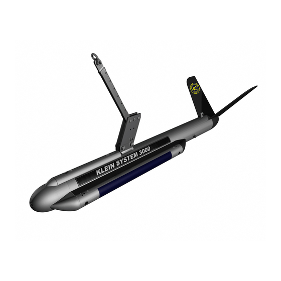
CHAPTER 1 Overview 1.3.2 Subsurface Equipment The subsurface equipment comprises the towfish, as shown in Figure 1-2, and a tow cable. Towfish Figure 1-2: The Towfish consists of a negatively buoyant tow body containing Towfish. port and starboard sonar transducers, processing and control electronics for sonar operation, a downlink demultiplexer for control signals, and an uplink multiplexer for sonar and auxiliary sensor data. -
Page 27: Theory Of Operation
Theory of Operation Theory of Operation This section provides a detailed functional description of the Series 3000 Sonar System operation. 1.4.1 Introduction The Series 3000 Sonar System is a single beam side-looking sonar intended for high resolution survey use. The Series 3000 departs from previous single beam systems in that the swath forming process is implemented digitally using digital signal processing (DSP), rather than analog delay lines, phase shifters, or multipliers and adders. - Page 28 CHAPTER 1 Overview NOTE The transducers are side specific and are not interchangeable. The two transducer arrays are each composed of piezoelectric ceramic sub-arrays that operate as both transmit and receive elements. Each set of sub-arrays is arranged into a continuous line array spanning an overall aperture of 48 centimeters.
- Page 29 Theory of Operation Multiplexer board E/O Interface Fiber Optic Tow Cable Tow Cable Power Splitter Data and 200 VDC Towfish Power Supply Multiplexed 200VDC Data +5 +15 Multiplexer Low Frequency Transceiver Board 100 kHz / 50 kHz option Port Transducer Data Starboard Transducer High Frequency Transceiver Board...
-
Page 30: Figure 1-4: Towfish Connector-At Towfish
CHAPTER 1 Overview The Multiplexer board digitizes the signals from each of Multiplexer board. the transducer sub-array channels along with the signals from the sensors, encodes the data, and transmits a high baud rate digital data stream to the TPU via the tow cable. - Page 31 Theory of Operation 1.4.3 Transceiver and Processing Unit The TPU provides signal processing along with the system control and data telemetry functions. The TPU is composed of two circuit boards: an embedded CPU board and a Demultiplexer board. The TPU also contains a 200-volt towfish power supply and a TPU power supply.
-
Page 32: Figure 1-6: Tpu Rear Panel
1-10 CHAPTER 1 Overview The data from the towfish arrives in serial NRZ format and is conditioned and input to the clock recovery circuit. The recovered clock is used to strobe the serial data into a line decoder. The decoded data is converted to parallel format and output the front panel connector. -
Page 33: Table 1-3: Ac Connector Pinouts
1-11 Theory of Operation TOWFISH Connector Pinouts Table 1-2: PIN NO. LABEL FUNCTION Center pin +200 VDC power and multiplexed data Shell Shield power and data return AC Connector Pinouts Table 1-3: PIN NO. LABEL FUNCTION AC line AC neutral Ground Table 1-4: COM1, COM 2, COM3, and COM4 Connector Pinouts... - Page 34 1-12 CHAPTER 1 Overview System Fuses Table 1-5: MANUFACTURER FUSE AMP/VOLT SIZE LOCATION TYPE Rear panel, 2 A, Slow-Blow 5 x 20 mm Main AC BUSS GMA above AC 250 V (two) power connector Rear panel 6.3 A below Towfish BUSS GMA 5 X 20 mm TOWFISH...
- Page 35 CHAPTER 2: S PECIFICATIONS This chapter includes the physical and performance specifications for the main components of the Series 3000 Sonar System. NOTE Specifications are typical and subject to change without notice. Sonar System Sonar channels: 100 kHz nominal (132 kHz, ±1% actual) Sonar frequencies: 500 kHz nominal (445 kHz, ±1% actual) Toneburst, operator selectable from 25 to...
-
Page 36: Chapter 2 Specifications
CHAPTER 2 Specifications Transceiver and Processing Unit (TPU) 2.2.1 TPU Operation The only operator control on the TPU is the main power switch. 2.2.2 Towfish Input/Output Quantity: Type N Connector: 2.2.3 Trigger/IRIG Input (Optional) The trigger/IRIG input, which is optional, is used to trigger the system externally. Quantity: TTL compatible, positive edge triggered Input level:... -
Page 37: Com 2 Port
Computer Display and Control Unit 2.2.6 RS-232 COM 2 Port Quantity: 4800 baud Baud rate: 9-pin DSUB for receiving navigation Connector: data 2.2.7 LAN Input/Output Port Quantity: 100BaseT Output: RJ-45 Connector: 2.2.8 Power Input 250 VA (nominal) Power consumption: 115 VAC, 50–60 Hz or 230 VAC, Input voltage: 50–60 Hz, manually selected 2.2.9... -
Page 38: Towfish
CHAPTER 2 Specifications Towfish 2.5.1 General Modular plug-in Electronics boards: 2.5.2 Transducers Proprietary line array Type: 40° Vertical beam angle: 1500 m standard; 3000 m and 6000 m Depth limit: optional 2.5.3 Transmitter Toneburst Type: 50 µs, 100 µs, 200 µs Pulse width: Class-D MOSFET Driver:... -
Page 39: Power
Towfish 2.5.7 Power Powered from the TPU; no additional Input power: power required 2.5.8 Physical Characteristics Type 316 stainless steel Body material: Hard-coat anodized 6061 aluminum Tail fin material: 127.8 cm (50.3 in.) long Size: 8.9 cm (3.5 in.) diameter 28.2 kg (62 lb) Weight in air: Weight in water:... -
Page 40: Tow Cables
CHAPTER 2 Specifications Tow Cables 2.6.1 Lightweight Tow Cable Polyurethane jacketed coaxial, Kevlar Type: reinforced Coaxial copper Conductors: 1.156 cm (0.455 in.) Diameter (OD): 2270 kg (5000 lb) Breaking strength: 454 kg (1000 lb) Working load: Operational length: 3000 m maximum 600 VDC Voltage rating: Stainless steel shackle at towfish end... -
Page 41: Towfish Options
Options 2.7.1 Towfish Options The towfish can be equipped with the following options: • Pressure sensor • Responder • Magnetometer 2.7.2 Tow Cable Options Three types of tow cables are available: • Lightweight coaxial • Armored coaxial • Armored fiber-optic... -
Page 43: Chapter 3: Setup And Test
Remove the computer from the shipping container, and set it on a sturdy, flat surface. Inspect the computer for signs of damage. If there is any damage or if any items are missing, immediately contact Klein Marine Systems, Inc. or your KMS sales representative. Record the serial numbers of the computer modules. -
Page 44: Unpacking The Towfish
The tow cable is shipped on a cable palette or reel. Inspect the cable for damage. If there is any damage or if any items are missing, immediately Klein Marine Systems, Inc. or your KMS sales representative. The TPU end of the cable has a Type N connector. -
Page 45: Power Requirements
Power Requirements Power Requirements The Series 3000 requires AC power to operate. The power source requirements are 115 VAC, 50–60 Hz, single phase or 230 VAC, 50–60 Hz. The system is designed to protect against over and under voltage and transient spikes. However, it is always best to check the power source carefully before operating the equipment. -
Page 46: Towfish Fuse
CHAPTER 3 Setup and Test 3.3.2 Towfish Fuse The towfish is protected by a 6.3-A, 5 x 20-mm slow blow fuse rated for 250 volts (P/N 13000163). It is located on the back panel of the TPU and is below the TOWFISH connector. -
Page 47: Towfish Setup
Towfish Setup Towfish Setup 3.5.1 General Rigging Notes and Cautions Grease the waterproof connectors when attaching the connectors at the towfish. Avoid putting excessive grease on the male pins. The silicone grease serves an important lubricating and corrosion protection function. Use a high quality, nonconducting grease such as Dow Corning DC-4. -
Page 48: Tow Cable Electrical Connection
CHAPTER 3 Setup and Test 3.5.2 Tow Cable Electrical Connection It is essential to exercise care when making and breaking the tow cable connections at both the TPU and the towfish ends. The electrical connection procedures are provided below. WARNING In all of the procedures which follow, be sure that the power is turned off. -
Page 49: Towfish And Optional Depressor Connection
Towfish Setup The tow cable jumper is secured with cable ties to the top of the towfish. The towfish mechanical and electrical connection procedure is as follows: Remove the retaining ring from the beveled end of the tow pin and withdraw the pin from the tow bracket. -
Page 50: Tow Cable Disconnection
If the tow cable is disconnected, however, it is very important that all connectors be properly maintained. Connectors must be kept clean and must remain out of the way of traffic while on deck. Klein Marine Systems, Inc. supplies dummy connectors which can be used to protect the underwater connectors on the towfish and cable when they are not mated to each other. -
Page 51: System Activation And Test
System Activation and Test WARNING Power to the sonar system must be turned off prior to connection or disconnection of the tow cable to either the towfish or the TPU, as serious damage may occur to the sonar system electronics or injury may occur to the operator as a result of this action. -
Page 52: Activating And Testing The System At Sea
3-10 CHAPTER 3 Setup and Test 6. Check the Ethernet Hub port status for two ports lit, if only the computer and the TPU are connected to the hub. 7. On the computer, start SonarPro and observe that the towfish is transmitting by viewing the output pulse in the Sonar Viewer window. -
Page 53: Chapter 4: Equipment Maintenance
CHAPTER 4: E QUIPMENT AINTENANCE This chapter provides instructions for equipment maintenance and includes guides for taking care of the equipment on a daily, weekly, and long term basis. In addition, instructions are provided for replacing the fixed tail cone assembly. Maintenance General Comments Equipment used at sea is subjected to severe environmental and handling conditions. -
Page 54: Weekly Maintenance Checklist
CHAPTER 4 Equipment Maintenance 4. Keep the tow cable plugged into the towfish, or use dummy plugs on the tow cable and towfish to keep the connectors from exposure to the salt atmosphere. Remember to put a thin film of silicone grease, such as Dow-Corning 4, on the rubber portion of the underwater connector every time the towfish is disconnected. -
Page 55: Chapter 5: Splashproof-Ii Tpu
SonarPro, a comprehensive Windows based software program, available from Klein Marine Systems, Inc., that provides multiple displays of real-time or saved sonar and sensor data and towfish status. -
Page 56: Functional Components
CHAPTER 5 Splashproof-II TPU Functional Components The SP-II TPU provides signal processing along with the system control and data telemetry functions. The SP-II TPU is composed of four circuit boards: a Computer Data Interface board (CDI), a CPU board, a Power Integration board, and a Panel Interconnect board. -
Page 57: Figure 5-2: Sp-Ii Tpu Electronics
Panel Interconnect board Power Integration board 12 VDC power supply board board Figure 5-2: SP-II TPU Electronics... -
Page 58: Figure 5-3: Sp-Ii Tpu Electronics Block Diagram
Figure 5-3: SP-II TPU Electronics Block Diagram... -
Page 59: Setting Up And Connecting The Sp-Ii Tpu
Setting up and Connecting the SP-II TPU Setting up and Connecting the SP-II TPU All the system components connect to the side panel of the SP-II TPU. This panel is shown in Figure 5-4. The connections are the following: 8-pin female bulkhead connector that connects to TOWFISH: the towfish using the tow cable. -
Page 60: Figure 5-4: Sp-Ii Tpu Front Panel
D/C POLARITY NAV connector indicator T/F TRIG indicator LOCK LOSS DEBUG connector indicator T/F PWR RESP TRIG indicator MAG connector indicator indicator TOWFISH D/C-A/C connector switch RESP TRIG 12 VDC 120/240 VAC connector connector connector connector T/F TRIG EXT TRIG IN 1PPS connector connector... -
Page 61: Table 5-1: Towfish Connector Pinout-At Towfish
Setting up and Connecting the SP-II TPU For the connector pinouts and pin orientations for each of the connectors on the SP-II TPU side panel, refer to Table 5-2 through Table 5-7 on page 5-8. For the connector pinout and orientation of the towfish connector at the towfish end, refer to Table 5-1 below. -
Page 62: Table 5-2: Lan Connector Pinouts
12 VDC Table 5-2: Table 5-3: Connector Pinouts Connector Pinouts FUNCTION FUNCTION Return +12 VDC 120/240 VAC TOWFISH Table 5-4: Table 5-5: Connector Pinouts Connector Pinouts FUNCTION FUNCTION Neutral 200 VDC Power and Telemetry Shield Line Table 5-6: NAV, DEBUG Table 5-7: T/F TRIG, and MAG Connector... -
Page 63: Figure 5-5: Basic System Setup Diagram With Towfish, Navigation And Laptop
Setting up and Connecting the SP-II TPU Sample navigation strings: The preferred is RMC $GPRMC,101842.572,A,3318.577,N,07845.424,W,7.452,2 45.4,050202,0.0,E*72 $GPVTG,245.4,T,245.4,M,7.5,N,13.8,K*76 However the following can also be used $GPGLL,3446.8877,N,07849.0595,W,091739.00,A*1d $GPVTG,290.0,T,290.0,M,06.6,N,12.2,K*4f Navigation System NMEA 0183 4800 baud Formats: GGA&VTG GLL&VTG or Towfish SP-II TPU Ethernet port Laptop computer Figure 5-5:... -
Page 64: Figure 5-6: System Setup Diagram With Towfish, Navigation, Acoustic Positioning
5-10 CHAPTER 5 Splashproof-II TPU Acoustic Tracking Navigation System Unit NMEA 0183 4800 baud Formats: GGA&VTG GLL&VTG or Depth Acoustic Positioning System Output Format: RMC and TLL or GLL&VTG and TLL or GGA&VTG and TLL Towfish SP-II TPU Ethernet port Laptop computer System Setup Diagram with Towfish, Navigation, Acoustic Positioning System, and... -
Page 65: Operator Controls And Indicators
5-11 Operator Controls and Indicators Operator Controls and Indicators All of operator controls and indicators are located on the connector panel of the SP-II TPU as shown in Figure 5-4 on page 5-6. They are the following: Green indicator that is illuminated when either AC PWR: or DC power is on. -
Page 66: Starting Linux Tpu Updater
Starting Linux TPU Updater Linux TPU Updater is started by double-clicking the Linux TPU Updater icon on the Windows desktop. The Klein Linux TPU Updater dialog box will open as shown Figure 5-7. The Klein Linux TPU Updater Dialog Box Figure 5-7: 5.6.2... -
Page 67: Figure 5-9: The Klein Linux Tpu Updater Dialog Box With Current Tpu Ip Address
7. From the Rate drop-down list box, select the baud rate of the SP-II TPU’s NAV serial port, or select Determine Automatically to have Linux TPU Updater find the rate. The Klein Linux TPU Updater dialog box opens with the current IP address displayed in the text box as shown in Figure 5-9. -
Page 68: Editing The Sp-Ii Tpu Startup File
D/C for DC operation. 4. Start Linux TPU Updater. The Klein Linux TPU Updater dialog box opens. 5. Enter the SP-II TPU IP address in the Enter TPU IP Address text box if it is different than the default address, or click if it is the default. -
Page 69: Activating The Sp-Ii Tpu
D/C for DC operation. 4. Start Linux TPU Updater. The Klein Linux TPU Updater dialog box opens. 5. Enter the SP-II TPU IP address in the Enter TPU IP Address text box if it is different than the default address, or click if it is the default. -
Page 70: Specifications
5-16 CHAPTER 5 Splashproof-II TPU NOTE Should the DC power cord be connected with the polarities reversed, the D/C POLARITY indicator will illuminate when the A/C-D/C switch is switched to D/C. Should this situation occur, reverse the connection. 5. Turn on the SP-II TPU by switching the A/C-D/C switch to A/C for AC operation or to D/C for DC operation. -
Page 71: Sp-Ii Tpu Drawings
5-17 SP-II TPU Drawings SP-II TPU Drawings Listed in Table 5-8 are the drawings and parts lists for the SP-II TPU. They are provided for reference and troubleshooting purposes. SP-II-TPU List of Drawings and Parts Lists Table 5-8: DRAWING PARTS TITLE LIST NO. - Page 73 5-19 SP-II TPU Drawings...
- Page 77 5-23 SP-II TPU Drawings...
- Page 79 5-25 SP-II TPU Drawings...
- Page 81 5-27 SP-II TPU Drawings...
-
Page 83: Chapter 6: Splashproof Tpu
CHAPTER 6: S PLASHPROOF For use in open boat operations where exposure to rain and spray is likely, a lightweight, rugged, splashproof configuration of the Transceiver and Processor Unit (TPU) is available. The Splashproof TPU is similar to the rack mount configuration but is housed in a watertight, corrosion proof, high impact resistant Pelican Protector Case. -
Page 84: Optional Wireless Router
CHAPTER 6 Splashproof TPU 6.1.1 Optional Wireless Router The optional wireless router provides a wireless network connection to a computer running SonarPro with a wireless Ethernet device. This wireless router is capable of providing sufficient data bandwidth to support the data throughput of the system. -
Page 85: External Connections
General Description 6.1.3 External Connections The external connections to the Splashproof TPU are made on the connector panel which is shown in Figure 6-4. The connector panel is also shown inside the case cover in Figure 6-5. Most of the connectors on this panel are wired to internal connectors which connect to the Demultiplexer and CPU boards as shown in Figure 6-6 on page 6-6. -
Page 86: Figure 6-5: Inside The Cover Of The Splashproof Tpu Case
CHAPTER 6 Splashproof TPU View ports Connector panel Splashproof TPU Connector Panel Figure 6-4: Baffle Antenna Wireless Baffles router Connector panel Inside the Cover of the Splashproof TPU Case Figure 6-5: Series 3000 Sonar System Operations and Maintenance Manual 11210066, Rev. 11... -
Page 87: Operator Controls And Indicators
General Description 8-pin bulkhead connector for receiving navigation GPS IN: data. This connector is internally wired to a 9-pin DSUB connector that connects to the COM1 connector of the Demultiplexer board and to the output of the 12 VDC power supply. 3-pin bulkhead connector that connects to either a 120/240 VAC: 115 or 230 VAC, 50–60 Hz power source. - Page 88 VME chassis COM1 CABLE COM2 DEBUG TRIG 1 Demultiplexer board CPU board VOLTAGE SELECT switch (See CAUTIONS on page 6-10.) Low voltage Inverter power supply Figure 6-6: Front Panel of VME Chassis inside Splashproof TPU...
-
Page 89: Figure 6-7: Vme Backplane And Power Supply Connections Inside
VME chassis VME backplane Low voltage power supply VME fan 200 VDC power supply Transformer Power fuse 12 VDC power supply Choke GPS fuse Towfish fuse Figure 6-7: VME Backplane and Power Supply Connections inside Splashproof TPU... -
Page 90: Functional Components
CHAPTER 6 Splashproof TPU The connector panel also includes two view ports, as shown in Figure 6-4 on page 6-4, which allow you to view the setting of the VOLTAGE SELECT switch and the indicators on the Demultiplexer and CPU boards. For information about the indicators, refer to APPENDIX C: “General Setup, Configuration and Troubleshooting.”... -
Page 91: Setting Up And Connecting The Splashproof Tpu
Setting up and Connecting the Splashproof TPU The power fuse is in series with the main AC power input, the Power fuse. transformer input and the input to the low voltage power supply. It is a 2-A, 5 x 20-mm slow-blow fuse rated for 250 volts (P/N 13000045). The towfish fuse is in series with the 200 VDC output of the Towfish fuse. -
Page 92: Included Accessories
6-10 CHAPTER 6 Splashproof TPU 6.2.1 Included Accessories The following accessories are included with the Splashproof TPU: • AC power cord • DC power cord • Towfish jumper cable • GPS connector • TRIG connector • Waterproof LAN cable 6.2.2 Connecting Power The TPU can be powered from a 115 VAC, 230 VAC or 12 VDC power source. -
Page 93: Activating The Splashproof Tpu
6-11 Activating the Splashproof TPU Activating the Splashproof TPU Activating the Splashproof TPU is similar to that of the rack mount TPU. SHOCK HAZARD Do not connect or disconnect the tow cable from the towfish or the TPU when power is on. Failure to follow this practice may result in personal injury and will damage the towfish or the TPU electronics, or both. -
Page 94: Specifications
6-12 CHAPTER 6 Splashproof TPU Specifications The specifications for the Splashproof TPU, except for those listed below, are the same as the rack mount TPU. Refer to CHAPTER 2: “Specifications,” for those specifications. NOTE Specifications are typical and subject to change without notice. 250 VA (nominal) Power consumption: 115 or 230 VAC, 50–60 Hz, manually... - Page 101 CHAPTER 7: S3000SBP C HIRP OTTOM ROFILER For combined side scan sonar and chirp sub bottom profiling, the S3000SPB Chirp Sub Bottom Profiler is available as an upgrade to the Series 3000 Towfish. The sub bottom profiler mounts directly to the towfish and connects to the towfish with supplied jumper cables.
-
Page 102: Chapter 7 S3000Sbp Chirp Sub Bottom Profiler
CHAPTER 7 S3000SBP Chirp Sub Bottom Profiler composite fairing. This assembly is mounted at the end of a spar which attaches to the towfish with the fairing located at the bow. Mounted to the opposite end of the spar is a tail fin. In addition, a receiver hydrophone is mounted under the towfish and secured in two places. - Page 103 Installing the Sub Bottom Profiler To mount the sub bottom profiler to the towfish: Raise the towfish off the floor on wooded blocks Tail fin (2) and orient it such that the middle tail fin is pointing straight up. Lock washer Using the 8-mm hex key, loosen the M10 socket head cap screw on the tail...
- Page 104 CHAPTER 7 S3000SBP Chirp Sub Bottom Profiler Using the 8-mm hex key, loosen the M10 socket head cap screw on the nose Nose cone cone, and then remove the nose cone. The screw remains captive to the nose. M10 Socket head cap screw Removing the Nose Cone Figure 7-4:...
- Page 105 Installing the Sub Bottom Profiler Cut the cable ties securing the tow cable jumper cable Cotter ring (Behind tow (not shown) to the tow bar. bracket) Do not disconnect the tow cable jumper cable from the towfish. Remove the cotter ring Tow bar from the clevis pin on the Clevis pin...
- Page 106 CHAPTER 7 S3000SBP Chirp Sub Bottom Profiler Remove the two tow brackets and the two hex head bolts that secure them. Store these components away. They will not be needed with the sub bottom profiler installed. Hex head bolt (2) Removing the Tow Brackets Figure 7-8: Slide the supplied aft sub...
- Page 107 Installing the Sub Bottom Profiler Insert a supplied 30-mm, M10 hex head bolt and lock washer through the bracket and into the stud weldment on the towfish. 30-mm, M10 hex head bolt and lock washer Inserting an M10 Hex Head Bolt Figure 7-10: and Lock Washer into the Aft Sub Bottom Towfish Mounting Bracket...
- Page 108 CHAPTER 7 S3000SBP Chirp Sub Bottom Profiler Using the 6-mm hex key, screw the two cross bar retaining screws—one on the top and one on the Cross bar bottom of the towfish at the retaining bow—into the cross bar screw (2) until they bottom out.
-
Page 109: Installing The Sub Bottom Profiler
Installing the Sub Bottom Profiler While laying the starboard transducer cable into the 30-mm, M10 slots in the forward sub hex head bottom towfish mounting bolt and lock washer bracket, one slot on each side of the bracket, insert a Stud supplied 30-mm, M10 hex head bolt and lock washer... - Page 110 7-10 CHAPTER 7 S3000SBP Chirp Sub Bottom Profiler Apply a thin film of silicone grease to the base (rubber part) of the pins of the hydrophone jumper cable, and then connect the Locking collar cable to the hydrophone. Do not over grease. Secure the locking collar to the hydrophone.
- Page 111 7-11 Installing the Sub Bottom Profiler Insert two of the supplied M5 socket head cap screws through the slots on either side of the forward sub bottom towfish mounting bracket, through the hydrophone and through the slots on the opposite side of the bracket.
- Page 112 7-12 CHAPTER 7 S3000SBP Chirp Sub Bottom Profiler Using the 6-mm hex key, remove the eight M8 socket head cap screws and washers that secure the top shell of the sub bottom transducer/electronics assembly. M6 socket head cap screw and washer (8) Removing the Top Shell of the Sub Figure 7-20:...
- Page 113 7-13 Installing the Sub Bottom Profiler Route the sub bottom and Sub bottom hydrophone jumper cables jumper cable through the hole in the sub Hydrophone jumper cable bottom transducer/ electronics assembly top plate next to the port sub bottom transducer as shown.
- Page 114 7-14 CHAPTER 7 S3000SBP Chirp Sub Bottom Profiler Connect the sub bottom Sub bottom and hydrophone jumper electronics cables to the sub bottom pressure case electronics pressure case as shown. The dummy plug and remaining cable are Factory connected factory connected. cable Hydrophone Factory...
- Page 115 7-15 Installing the Sub Bottom Profiler Lift the stern of the towfish and align the holes in the aft sub bottom towfish bracket with the holes in the spar. NOTE The tow point on the towfish should also slide into a slot under the spar.
- Page 116 7-16 CHAPTER 7 S3000SBP Chirp Sub Bottom Profiler Route the tow cable jumper cable (not shown) along the tow bar and use cable ties Tow bar to secure the cable. Tow Bar for Routing the Tow Figure 7-28: Cable Jumper Cable The final assembly of the sub bottom profiler to the towfish should be as...
-
Page 117: S3000Sbp Chirp Sub Bottom Profiler Drawings
7-17 S3000SBP Chirp Sub Bottom Profiler Drawings S3000SBP Chirp Sub Bottom Profiler Drawings Listed in Table 7-1 are the assembly drawings and parts lists for the S3000SBP Chirp Sub Bottom Profiler. They are provided for reference and troubleshooting purposes. Each assembly drawing is followed by its corresponding parts list. List of Drawings and Parts Lists Table 7-1: DRAWING... - Page 119 7-19 S3000SBP Chirp Sub Bottom Profiler Drawings...
- Page 124 7-24 CHAPTER 7 S3000SBP Chirp Sub Bottom Profiler Series 3000 Sonar System Operations and Maintenance Manual 11210066, Rev. 11...
-
Page 125: Appendix A: Notes On Handling Tow Cables
APPENDIX A: N OTES ON ANDLING ABLES A few methods on how to safely unreel tow cables are provided in this appendix. In addition, how cable kinking can occur is identified along with what can result from this condition. A.1 Unreeling Tow Cable The reel should be revolved and the rope taken off the way it was put on the reel as shown in Figure A-1 for two effective methods. -
Page 126: Uncoiling Tow Cable
APPENDIX A Notes on Handling Tow Cables A.2 Uncoiling Tow Cable Remove ties and roll the coil along the ground so the rope lies straight. There will be no twist or kink in the cable if these instructions are followed. CAUTION If the reel and coil do not revolve freely, it will cause the cable to twist as each turn is taken off. -
Page 127: Effect Of Cable Kinking
Cable Kinking Cable Loop Cable Kink Cable Loop and Kink Figure A-3: A.3.2 Effect of Cable Kinking The effect of kinking is shown in Figure A-4. The cable is permanently damaged Damaged Cable Figure A-4: A.3.3 Result of Cable Kinking The result of cable kinking is that strands and wires are displaced, creating uneven tension which causes excessive wear at the point of the kink. -
Page 129: Control Methods
APPENDIX B: TPU S OFTWARE NTERFACE ONTROL This appendix describes the various control and initialization procedures for the 3000, 5000 and 5900 Sonar System TPUs. The information in this document applies to TPU software version 5.3 and later. B.1 Control Methods Aside from control of the TPU via the Ethernet interface, the 3000/5000/5900 System may be controlled via NMEA messages or via a startup script file. - Page 130 APPENDIX B TPU Software Interface and Control off, d = 1 is low, d = 2 is medium and d = 3 is high. Default is off. SPEEDFILTERSWITCH {d = 0,1}. Turn velocity filter on|off, where d = 0 is off and d = 1 is on.
-
Page 131: Startup Script
Startup Script STANDBYMODE {d = 0,1,2}. Setting this to ‘1’ instructs the sonar to enter standby mode immediately on power-up. Setting this to ‘0’ instructs the sonar to starting "pinging" as soon as boot-up is completed. Setting this to ‘2’ tells the system to enter standby on power-up but shut off towfish power. - Page 132 APPENDIX B TPU Software Interface and Control SUBBOTTOM {d = 0,1} (System 3000 Only). Setting d = '1' indicates the Towfish has the sub bottom profiler option. Enabling this option will cause the TPU to allow the sub bottom profiler to be enabled and sub bottom data collected.
- Page 133 "startup script" parameter field in the boot configuration. (See “TPU LAN Configuration Setup” on page C-5 for details on boot parameters.) For example: if the file is located in /klein, then the "startup script" parameter must be set to /klein/ startup.ini.
- Page 134 APPENDIX B TPU Software Interface and Control SonarPro connected as master) then many of the commands will have no effect as there can only be one master and the software request to change a parameter will be rejected because there is an existing master. Many commands will echo the current setting if the data field is replaced with "?".
-
Page 135: Remote Control
Remote Control Format the hard-drive. WARNING: this will erase all data. Only use if a new disk has been installed. Note: only supported if local disk-drive option installed. Set the length of the recorded files where d is the number of FLdddd: pings per file. - Page 136 APPENDIX B TPU Software Interface and Control Synchronize the internal clock. The <data> field is defined SC<data>: as follows: mm,dd,yyyy,hh,mm,ss,mmm which is month, day, year (4 digit), hours, minutes, seconds, and milliseconds. Prepare the system for shutdown. This puts the system in standby, stops any recording, and closes all files.
-
Page 137: Snapshots
Snapshots Turn velocity filter on|off, where d = 0 is off and d = 1 is on. VFd: Default is on. Set transmit waveform, where d = 0 is 50 µs, d = 1 is 100 µs WFd: and d = 2 is 200 µs. Default = 50 µs An example command: $PKLA,DM2*5E<CR><LF>... -
Page 138: Messages
B-10 APPENDIX B TPU Software Interface and Control B.5 Messages B.5.1 Status Message Upon query of the system by the ST (status) command the system outputs a status message of the form: $PKLA,ST,RSdWFdRMdSMdDMdTPdVFdRCdSDdHDddERdd*hh<CR><LF> where the fields are as described above and HD is the percentage of hard drive space used and ER is an error/health monitoring byte (in ASCII hex representation) where zero indicates normal operation and a non-zero value indicates an error state defined as:... -
Page 139: Heartbeat Message
B-11 Messages TPU watchdog. If this bit is set then a task may be locked. The TPU uses multi-threaded OS technology where multiple tasks are performed simultaneously. These tasks include acquiring the data, formatting it, parsing the sensor messages, handling navigation input, etc. A software error can cause a thread to cease execution although this is extremely rare. -
Page 140: Towfish Commands
B-12 APPENDIX B TPU Software Interface and Control B.6 Towfish Commands Although sonar control is normally performed using the Ethernet or NMEA interfaces, direct control of the towfish is possible. Various parameters of sonar operation are performed in the towfish, such as waveform selection, TVG page, etc. -
Page 141: Auxiliary And Compass Commands
B-13 Towfish Commands Sets the responder divisor to 2^d, where d = 0 – 15. A value $MDd: of 15 turns the responder off. Sets the low-frequency waveform. This command should $MAd: not be issued by the user as damage to the transmit electronics could result if an inappropriate waveform is selected. -
Page 142: Datalogger On/Off Commands
B-14 APPENDIX B TPU Software Interface and Control d = 3: Generate a sawtooth waveform by holding the low 12 bits at 0xFFF, and incrementing a 12-bit counter every sample time to drive the high 12 bits. d = 4: Reserved. -
Page 143: Appendix C: General Setup, Configuration And Troubleshooting
WARNING Klein Marine Systems, Inc. recommends all troubleshooting be done by a trained technician. Some circuits in the Sonar Transceiver and Processing Unit have voltages as high as 240 volts, and some circuits in the sonar towfish have 1500 volts. -
Page 144: Basic System Requirements
APPENDIX C General Setup, Configuration and Troubleshooting C.1 Basic System Requirements Although we suggest that you get the fastest available computer at the time of purchase, it is recommended that you use the following minimum PC system. • 400 MHz Pentium II •... -
Page 145: Figure C-1: Basic System Setup Diagram
Basic System Setup Sample navigation strings: The preferred is RMC $GPRMC,101842.572,A,3318.577,N,07845.424,W,7.452,2 45.4,050202,0.0,E*72 $GPVTG,245.4,T,245.4,M,7.5,N,13.8,K*76 However the following can also be used $GPGLL,3446.8877,N,07849.0595,W,091739.00,A*1d $GPVTG,290.0,T,290.0,M,06.6,N,12.2,K*4f Navigation Unit NMEA 0183 4800 baud Formats: RMC or Slip Ring GLL&VTG or GGA&VTG Computer Terminal or PC boot device processor number Running HyperTerminal for... - Page 146 APPENDIX C General Setup, Configuration and Troubleshooting Navigation Unit Acoustic Tacking Unit NMEA 0183 NMEA 0183 4800 Baud Formats: RMC, or GLL&VTG, Depth or GGA&VTG from PC COM 2 Navigation Computer System Output Format: Slip Ring RMC and TLL or GLL&VTG and TLL or GGA&VTG and TLL Computer...
- Page 147 Press any key to stop auto-boot... auto-booting... boot device : fei unit number processor number host name : sonarclient file name : \klein\vxWorks inet on ethernet (e) : 192.168.0.81 host inet (h) : 192.168.0.82 user (u) : klein ftp password (pw) : klein...
- Page 148 ##### ####### # # | | 3333333333 000000000 000000000 00000000 3333333333 0 | | 333333333 000000000 000000000 000000000 ------------------------------------------------- Copyright (C) 2002 Klein Associates, Incorporated | |____________________________________________________________| | +----------------------------------------------------------------+ Series 3000 Sonar System Operations and Maintenance Manual 11210066, Rev. 11...
-
Page 149: Tpu Lan Configuration Setup
$ML7 $MH0 $MH0 $MH0 $MA0 $MA0 $MA0 $MB0 $MB0 $MB0 $MDF $MDF $MDF $MF7 $MF7 $MF7 Opening script file on sonarclient:\klein\startup.ini Processing startup script: $MDF $MDF $MDF $MF7 $MF7 $MF7 $ML1 $ML1 $ML1 $MH0 $MH0 $MH0 $PS1 $PS1 System Ready. - Page 150 (s) : \klein\startup.ini...Location of startup.ini file Turn the TPU off and then back on and watch the boot sequence again. The Klein startup.ini file is used to set boot parameters. The following is a typical .ini file. set SONARTYPE 3000...
- Page 151 TPU LAN Configuration Setup SonarPro needs to know the IP address of the TPU. Start SonarPro, and then click to connect to the towfish in real time. The TPU Connection dialog box will open. Enter the TPU IP address into the dialog box if different.
-
Page 152: Tow Cable Considerations
C-10 APPENDIX C General Setup, Configuration and Troubleshooting C.4 Tow Cable Considerations For lightweight tow cables, we recommend that you use tow cables with the following characteristics: Polyurethane jacketed, coaxial Kevlar Type: reinforced Coaxial copper Conductors: 1.03 cm (0.405 in.) Diameter (OD): 2270 kg (5000 lb) Breaking strength:... -
Page 153: Measuring Cable Insertion Loss
C-11 Tow Cable Considerations C.4.1 Measuring Cable Insertion Loss To get an accurate assessment of your tow cable assembly, we suggest that you use a Hewlett Packard 4194A Impedance/Gain-Phase Analyzer or similar. A sample plot is shown in Figure C-3. Figure C-3: Sample Plot of Tow Cable Characteristics If you do not have access to a Hewlett Packard 4194A Impedance/Gain-Phase... -
Page 154: Transceiver And Processing Unit
C-12 APPENDIX C General Setup, Configuration and Troubleshooting With the function generator and the oscilloscope connected to the cable, monitor input on the oscilloscope and input a 1 volt peak (2 volt peak-to-peak) sine wave of the specific frequency of interest. Measure the peak output at the other end of the cable on the scope through the 50-ohm termination. -
Page 155: Transceiver And Processing Unit
C-13 Transceiver and Processing Unit The rear panel of the TPU is shown in Figure C-6. TPU Rear Panel Figure C-6: C.5.1 Input Power Check the rear panel of the TPU for the proper AC input voltage setting, 120 VAC or 240 VAC. -
Page 156: Tpu Block Diagram
C-14 APPENDIX C General Setup, Configuration and Troubleshooting C.5.3 TPU Block Diagram The TPU block diagram is shown in Figure C-7. Main Input 200 VDC Power On/Off Towfish Fuse Fuse Tow Cable 120/240 Splitter Switch Data and 200VDC Power Supply (switchable) Power Supply 100 Base Tx LAN... -
Page 157: Power Supplies
C-15 Transceiver and Processing Unit C.5.5 Power Supplies The TPU includes a low voltage and a high voltage power supply as shown in Figure C-8. Low Voltage and High Voltage Power Supplies Figure C-8: The high voltage power supply supplies 200 VDC power to the towfish and is fused on the back of the TPU. -
Page 158: Figure C-9: Measuring The 200 Vdc Output To The Towfish
C-16 APPENDIX C General Setup, Configuration and Troubleshooting Measuring the 200 VDC Output to the Towfish Figure C-9: Test Points for +5 VDC, +12 VDC and -12 VDC Outputs Figure C-10: Series 3000 Sonar System Operations and Maintenance Manual 11210066, Rev. 11... -
Page 159: Board Locations
C-17 Transceiver and Processing Unit C.5.6 Board Locations The location of the Demultiplexer, optional IRIG and CPU boards in the TPU is shown in Figure C-11. Location of the Demultiplexer, optional IRIG and CPU Boards Figure C-11: in the TPU C.5.7 Access Panel To access the boards in the TPU, loosen the four captive screws on the access panel, two each on the left and right sides. -
Page 160: Com Port Wiring
C-18 APPENDIX C General Setup, Configuration and Troubleshooting With the access panel removed, the TPU appears as shown in Figure C-13. TPU with Access Panel Removed Figure C-13: C.5.8 COM Port Wiring The COM port wiring on the TPU, from the front panel of the Demultiplexer and CPU boards to the rear panel of the TPU, is shown in Table C-1. - Page 161 C-19 Transceiver and Processing Unit To power up the TPU and verify proper operation of the TPU and LAN: 1. With the towfish and LAN cables removed from the TPU, turn the power on, listen for the cooling fan to come on, and then measure the voltage at the TOWFISH connector which should be 200 VDC.
-
Page 162: Tpu Cooling
C-20 APPENDIX C General Setup, Configuration and Troubleshooting C.5.10 TPU Cooling For proper unit cooling, any unused board slots should be closed with a blank panel. The TPU also has an air filter which is accessible from the right side of the front panel as shown in Figure C-14. -
Page 163: Towfish Block Diagram
C-21 Towfish C.6.1 Towfish Block Diagram The towfish block diagram is shown in Figure C-16. Multiplexer board E/O Interface Fiber Optic Tow Cable Tow Cable Power Splitter Data and 200 VDC Towfish Power Supply Multiplexed 200VDC Data +5 +15 Multiplexer Low Frequency Transceiver Board 100 kHz / 50 kHz option Port Transducer... -
Page 164: Checking The Telemetry Link To The Towfish
C-22 APPENDIX C General Setup, Configuration and Troubleshooting C.6.2 Checking the Telemetry Link to the Towfish Turn the TPU on and check the CARRIER LOSS and LOCK LOSS lights. The lights should be off. If they are on or flickering, there is a problem. Again, a telemetry link problem could be one or more of the following: towfish fuse failure, cable assembly problems, miswire, open, using too long a cable, using wrong type of cable, or a failure in the towfish. -
Page 165: Removing The Towfish Electronics
C-23 Towfish 500 kHz 100 kHz Image in Sonar Viewer Windows During a Rub Test Figure C-18: C.6.5 Removing the Towfish Electronics To remove the towfish electronics: 1. Remove the towfish nose cone by unscrewing the socket head cap screw in the center with a 8-mm hex key or driver. -
Page 166: Figure C-19: Towfish Electronics Extraction Handle And Feed-Thrus
C-24 APPENDIX C General Setup, Configuration and Troubleshooting Towfish Electronics Extraction Handle and Feed-Thrus Figure C-19: One of Two 6-mm Hex Locking Screws in the Towfish Figure C-20: Electronics Extraction Handle Series 3000 Sonar System Operations and Maintenance Manual 11210066, Rev. 11... -
Page 167: Figure C-21: Towfish Electronics
C-25 Towfish 2. Slide the electronics assembly gently and carefully into the housing, positioning the extraction handle such that the “UP” label is at the top as shown in Figure C-19 on page C-24. 3. Once properly seated unscrew the 6-mm set screws in the top and bottom of the extraction handle to lock the feed-thru in the housing. -
Page 168: Feed-Thru Connector Pin Orientations And Pinouts
C-26 APPENDIX C General Setup, Configuration and Troubleshooting C.6.6 Feed-Thru Connector Pin Orientations and Pinouts The feed-thru connector pin orientations and pinouts are shown in Figure C-22. Feed-Thru Connector Pin Orientations and Pinouts Figure C-22: Series 3000 Sonar System Operations and Maintenance Manual 11210066, Rev. -
Page 169: Setting Up For Testing The Electronics
C-27 Towfish C.6.7 Setting up for Testing the Electronics Remove the towfish electronics as described in “Removing the Towfish Electronics” on page C-23 and place the electronics in a position so that you can reconnect the transducers and cable. The towfish electronics is shown removed and ready for servicing in Figure C-23. -
Page 170: Figure C-24: Sma Connector
C-28 APPENDIX C General Setup, Configuration and Troubleshooting CAUTION Do not short the high voltage connection. The towfish requires 200 VDC from the TPU to operate. Using a voltmeter check for 200 VDC at the TOWFISH connector of the TPU. Measure the voltage between the center pin to the side of the connector. -
Page 171: Figure C-25: Data Output Signals On Tp1 Of The Multiplexer Board Before Being
C-29 Towfish Data Output Signals on TP1 of the Multiplexer Board before Figure C-25: being coupled to 200 VDC The data output signals at TP2 are shown in Figure C-26. Data Output Signals on TP2 of the Multiplexer Board Figure C-26: TP7 in Figure C-27 shows the trigger FSK signals. -
Page 172: Figure C-27: Trigger Fsk Signals On Tp7 Of The Multiplexer Board
C-30 APPENDIX C General Setup, Configuration and Troubleshooting Trigger FSK Signals on TP7 of the Multiplexer Board Figure C-27: TP5 in Figure C-28 shows the uplink data signals. Check here if the towfish is transmitting but there are data problems. Data Uplink Signals on TP5 of the Multiplexer Board Figure C-28: Each Transceiver board has a TVG curve that controls the signal gain. -
Page 173: Multiplexer Connectors
C-31 Towfish TVG Signal on TP6 of the 500-kHz Transceiver Board Figure C-29: C.6.9 Multiplexer Connectors The connectors on the Multiplexer board are shown in Figure C-30. Multiplexer Board Connectors Figure C-30:... -
Page 174: Magnetometer Voltage
C-32 APPENDIX C General Setup, Configuration and Troubleshooting C.6.10 Magnetometer Voltage The power voltage for an optional magnetometer is set on the Multiplexer board with a jumper on JP2. The power supply for the optional magnetometer is shown in Figure C-31. The jumper positions are the following: •... -
Page 175: Checking The Transceiver Boards
C-33 Towfish +15 VDC -15 VDC +5 VDC +200 VDC Low Voltage Power Supply Connector Pinouts Figure C-32: C.6.12 Checking the Transceiver Boards Before checking the Transceiver boards, make sure the Multiplexer board is functioning properly. A Transceiver board is shown in Figure C-33. Next, verify the following voltages on the Transceiver board: •... -
Page 176: Figure C-34: C8 And C9 On Transceiver Board
C-34 APPENDIX C General Setup, Configuration and Troubleshooting C8 and C9 on Transceiver Board Figure C-34: Check for a trigger signal on Pin 21. The trigger signal should be as shown in Figure C-35. Trigger Signal on Pin 21 of the Transceiver Board Figure C-35: Series 3000 Sonar System Operations and Maintenance Manual 11210066, Rev. -
Page 177: Figure C-36: 100-Khz Transmit Waveform
C-35 Towfish Lay an oscilloscope probe, with the tip on, against the +transducer lead on each Transceiver board and verify the transmit pulses as shown in Figure C-36 for the 100-kHz Transceiver board and in Figure C-37 for the 500-kHz Transceiver board. 100-kHz Transmit Waveform Figure C-36: 500-kHz Transmit Waveform... -
Page 178: Checking The Fets
C-36 APPENDIX C General Setup, Configuration and Troubleshooting C.6.13 Checking the FETs If you are having transmitter problems, you can check FETs Q1, Q2, Q3, and Q4 on the Transceiver boards with a multimeter. These FETs are shown in Figure C-38. Checking the FETs on the Transceiver Board Figure C-38: Measure the resistance across each of the FETs as shown in Figure C-38. -
Page 179: Checking The Receiver Section
C-37 Towfish C.6.14 Checking the Receiver Section If your sonar image seems to be having problems on one side, this is an indication that you may have a receiver problem. Try swapping to a spare Transceiver board to see if the problem follows the board. Alternately you can swap the transducers at the feed-thru to see if the problem stays the same (still most likely a board problem), or if it changes sides, it could possibly be a transducer problem. -
Page 180: Calibrating The Compass
C-38 APPENDIX C General Setup, Configuration and Troubleshooting C.6.16 Calibrating the Compass Starting with version SonarPro 5.2 a Compass Calibration Wizard was added. To start the Compass Calibration Wizard, click Run Compass Calibration Wizard on the Towfish Diagnostics tab of the Sonar Interface dialog box. Follow the instructions and play the demonstration animation. -
Page 181: Calibrating The Compass With A Magnetometer (Optional
Before running the compass calibration, you must turn off the magnetometer uplink. To calibrate the compass with a magnetometer: 1. Open the startup.ini file in the klein directory. 2. Change the line set DEFAULTUPLINK 1 to set DEFAULTUPLINK 0. 3. Save the startup.ini file. -
Page 182: Software Troubleshooting
Registry. To edit the registry: 1. Select Start/Run, enter REGEDT in the Open text box, and then click OK . 2. Navigate the path My Computer/HKEY_CURRENT_USER/Software/Klein Associates. 3. Select and then delete SonarPro. 4. Start SonarPro, and then select New State from the Session Menu. - Page 183 TPU will not boot. The likely cause is the failure of the backup battery on the CPU board. Error in boot line. Contact Klein Marine Systems, Inc. for a Gibberish data. replacement. "Can’t load boot file!!" message. See “Replacing the CPU Battery” on page C-42 for battery replacement instructions.
-
Page 184: Replacing The Cpu Battery
C-42 APPENDIX C General Setup, Configuration and Troubleshooting C.8.1 Replacing the CPU Battery If you have problems with the TPU booting up and you get the error message "Error in boot file!!" along with a boot up screen similar to that shown in Figure C-40, the likely cause is the failure of the backup battery on the CPU board. -
Page 185: Recommended Test Equipment
C-43 Problem Troubleshooting C.8.2 Recommended Test Equipment The following equipment is recommended when servicing or performing troubleshooting operations. • Fluke 87 multimeter • Tektronix TDS 3014 4-channel digital oscilloscope or a THS720A 2-channel digital oscilloscope • Terminal program such as HyperTerminal •... -
Page 186: Current Draw
C-44 APPENDIX C General Setup, Configuration and Troubleshooting Towfish Spares Table C-4: DESCRIPTION Multiplexer board 100-kHz Transceiver board 500-kHz Transceiver board Compass assembly Power Supply C.8.4 Current Draw The following is the system current draw and power under various operating conditions at 120 VAC: 0.5 A, no towfish connected TPU Standby:... -
Page 187: Nmea 0183 Formats And Information
C-45 NMEA 0183 Formats and Information The formula for PRF/Period is T = 2R/C where, T = Time R = Range C = Speed of sound in water = 1500 m/s Therefore, T = 2R/1500 C.9 NMEA 0183 Formats and Information... - Page 188 C-46 APPENDIX C General Setup, Configuration and Troubleshooting Series 3000 Sonar System Operations and Maintenance Manual 11210066, Rev. 11...
- Page 189 C-47 NMEA 0183 Formats and Information...
-
Page 190: Tpu Operating System Notes (Vxworks
C-48 APPENDIX C General Setup, Configuration and Troubleshooting C.10 TPU Operating System Notes (vxWorks) • CPU version 14102073 recognized by unpopulated area near front of board can only be used with vxWorks version 5.5.0291 or earlier. This board may be reflashed with an updated boot file to make it compatible with the newer vxWorks files. -
Page 191: Appendix D: Setting Up The System For A Magnetometer
• 3-4 for +5 volts • 5-6 for +12 volts • 7-8 for +200 volts The Klein startup.ini file located in the klein folder is used to set boot parameters. The following is a typical .ini file: set SONARTYPE 3000... - Page 192 APPENDIX D Setting up the System for a Magnetometer When adding a magnetometer o the system, the startup.ini file must be modified by adding the line set DEFAULTUPLINK 1. The new startup.ini file will be the following: set SONARTYPE 3000 set RANGE 2 set RESPDIV 15 set RESPFREQ 7...
-
Page 193: Connecting The Magnetometer For Data Transfer
Connecting the Magnetometer for Data Transfer NOTE When calibrating the compass, the default uplink has to be set to 0. NOTE The startup.ini is a text file and may be edited in any word processing program such as Wordpad. D.2 Connecting the Magnetometer for Data Transfer There are several ways to connect to the magnetometer for data transfer. -
Page 194: Method 3
APPENDIX D Setting up the System for a Magnetometer D.2.3 Method 3 1. Connect the magnetometer PC to COM4 on the TPU using a straight (non null modem) RS-232 cable. 2. Configure your terminal or software for 9600-8-N-1, and set flow control to none. 3. - Page 195 APPENDIX E: D RAWINGS AND ARTS ISTS Listed in Table E-1 are the drawings and parts lists included in this appendix. They are provided for reference and troubleshooting purposes. Each assembly drawing is followed by its corresponding parts list. Table E-1: List of Drawings and Parts Lists DRAWING PARTS LIST...
-
Page 206: Appendix E Drawings And Parts Lists
E-12 APPENDIX E Drawings and Parts Lists Series 3000 Sonar System Operations and Maintenance Manual 11210066, Rev. 11...
Need help?
Do you have a question about the 3000 Series and is the answer not in the manual?
Questions and answers