Sign In
Upload
Manuals
Brands
Klein Manuals
Sonar
3000 Series
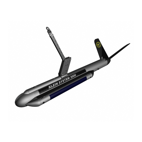
Klein 3000 Series Manuals
Manuals and User Guides for Klein 3000 Series. We have
3
Klein 3000 Series manuals available for free PDF download: Operation And Maintenance Manual, Troubleshooting Manual, Quick Start Manual
Klein 3000 Series Operation And Maintenance Manual (206 pages)
Brand:
Klein
| Category:
Sonar
| Size: 73.35 MB
Table of Contents
Table of Contents
4
List of Figures
11
Sonar System Warranty
16
What Is Covered
16
Conditions of Warranty
17
Changes, Errors and Ommissions
18
Software License Agreement
19
Preface
21
What's in this Manual
21
Note, Warning, and Caution Notices
22
Customer Service
22
CHAPTER 1: Overview
23
Equipment
23
Single Beam Sonar Instrumented Towfish
23
Transceiver and Processing Unit (TPU)
23
Computer Display and Control Unit
24
Features
24
Tow Cable
24
Figure 1-1: TPU Front Panel
25
Physical Description
25
Surface Equipment
25
Subsurface Equipment
26
Introduction
27
Theory of Operation
27
Figure 1-4: Towfish Connector-At Towfish
30
Figure 1-6: TPU Rear Panel
32
Table 1-3: AC Connector Pinouts
33
CHAPTER 2 Specifications
36
Transceiver and Processing Unit (TPU)
36
TPU Operation
36
Towfish Input/Output
36
Trigger/Irig Input (Optional)
36
Trigger Outputs
36
COM 1, COM3 and COM4 Ports
36
COM 2 Port
37
LAN Input/Output Port
37
Power Input
37
Physical Characteristics
37
Computer Display and Control Unit
37
Ethernet Hub
37
Towfish
38
General
38
Transducers
38
Transmitter
38
Receiver
38
A/D Converter
38
Multiplexer
38
Power
39
Physical Characteristics
39
Heading Sensor
39
Pitch and Roll Sensor
39
Pressure Sensor (Optional)
39
Tow Cables
40
Lightweight Tow Cable
40
Steel Tow Cable
40
Options
40
Towfish Options
41
Tow Cable Options
41
CHAPTER 3: Setup and Test
43
Unpacking and Inspection
43
Unpacking the Computer Display and Control Unit (Computer)
43
Unpacking the TPU
43
Isolating from Shock and Vibration
44
Location
44
Mechanical Installation of the TPU and Computer
44
Mounting
44
Unpacking the Tow Cable
44
Unpacking the Towfish
44
Power Line Fuse
45
Power Requirements
45
Connecting Cables and Power Cords
46
Grounding
46
Towfish Fuse
46
General Rigging Notes and Cautions
47
Towfish Setup
47
Figure 3-1: Towfish Connection
48
Tow Cable Electrical Connection
48
Towfish and Optional Depressor Connection
49
Tow Cable Disconnection
50
Activating and Testing the System on Deck
51
System Activation and Test
51
Activating and Testing the System at Sea
52
CHAPTER 4: Equipment Maintenance
53
Maintenance General Comments
53
Maintenance Checklists
53
Daily Maintenance Checklist
53
Weekly Maintenance Checklist
54
Long Term Maintenance Checklist
54
CHAPTER 5: Splashproof-II TPU
55
Figure 5-1: Splashproof-II TPU
55
General Description
55
Functional Components
56
Included Accessories
56
Figure 5-2: SP-II TPU Electronics
57
Figure 5-3: SP-II TPU Electronics Block Diagram
58
Setting up and Connecting the SP-II TPU
59
Figure 5-4: SP-II TPU Front Panel
60
Table 5-1: Towfish Connector Pinout-At Towfish
61
Table 5-5: TOWFISH Connector Pinouts
62
Table 5-4: 120/240 VAC Connector Pinouts
62
Table 5-7: T/F TRIG, RESP TRIG, 1PPS, and EXG TRIG in Pinouts
62
Table 5-2: LAN Connector Pinouts
62
Figure 5-5: Basic System Setup Diagram with Towfish, Navigation and Laptop
63
Figure 5-7: the Klein Linux TPU Updater Dialog Box
66
Figure 5-9: the Klein Linux TPU Updater Dialog Box with Current TPU IP Address
67
Editing the SP-II TPU Startup File
68
Updating the SP-II TPU Software
68
Activating the SP-II TPU
69
Specifications
70
SP-II TPU Drawings
71
Table 5-6: NAV, DEBUG and MAG Connector Pinouts
62
Table 5-3: 12 VDC Connector Pinouts
62
Figure 5-6: System Setup Diagram with Towfish, Navigation, Acoustic Positioning
64
Configuring and Updating the SP-II TPU
65
Operator Controls and Indicators
65
Querying or Changing the SP-II TPU IP Address
66
Starting Linux TPU Updater
66
Table 5-8: SP-II-TPU List of Drawings and Parts Lists
71
CHAPTER 6: Splashproof TPU
83
Figure 6-1: Splashproof TPU
83
General Description
83
Figure 6-3: Splashproof TPU Vent Open
84
Figure 6-5: Inside the Cover of the Splashproof TPU Case
86
Figure 6-7: VME Backplane and Power Supply Connections Inside
89
Functional Components
90
Setting up and Connecting the Splashproof TPU
91
Connecting Power
92
Included Accessories
92
Activating the Splashproof TPU
93
Specifications
94
Splashproof TPU Drawings
94
Figure 6-2: Splashproof TPU Vent Closed
84
Operator Controls and Indicators
87
Optional Wireless Router
84
Venting the Splashproof TPU
84
External Connections
85
CHAPTER 7 S3000SBP Chirp Sub Bottom Profiler
102
Specifications
102
Installing the Sub Bottom Profiler
109
S3000SBP Chirp Sub Bottom Profiler Drawings
117
Table 7-1: List of Drawings and Parts Lists
117
Figure A-1: Correct Methods to Unreel Tow Cable
125
Cable Kinking
126
Cause of Cable Kinking
126
Uncoiling Tow Cable
126
Effect of Cable Kinking
127
Result of Cable Kinking
127
APPENDIX A: Notes on Handling Tow Cables
125
Unreeling Tow Cable
125
Figure A-3: Cable Loop and Kink
127
Figure A-4: Damaged Cable
127
APPENDIX B: TPU Software Interface and Control
129
Control Methods
129
Startup Script
131
Remote Control
135
Snapshots
137
Messages
138
Status Message
138
Heartbeat Message
139
Sensor Message
139
Towfish Commands
140
3000 System Multiplexer Commands
140
Auxiliary and Compass Commands
141
System X000 Sub-Bottom Profiler (SBP) Commands
141
Datalogger On/Off Commands
142
APPENDIX C: General Setup, Configuration and Troubleshooting
143
Basic System Requirements
144
Basic System Setup
144
Figure C-1: Basic System Setup Diagram
145
Figure C-5: the Transceiver and Processing Unit (TPU
154
Figure C-6: TPU Rear Panel
155
Figure C-7: TPU Block Diagram
156
TPU Block Diagram
156
TPU Internal Access
156
Power Supplies
157
Input Power
155
Towfish Fuse
155
Transceiver and Processing Unit
155
TPU LAN Configuration Setup
149
Tow Cable Considerations
152
Measuring Cable Insertion Loss
153
Spare Tow Cable
154
Transceiver and Processing Unit
154
Figure C-8: Low Voltage and High Voltage Power Supplies
157
Figure C-10: Test Points for +5 VDC, +12 VDC and -12 VDC Outputs
158
Figure C-11: Location of the Demultiplexer, Optional IRIG and CPU Boards
159
Figure C-12: Left Two Captive Screws on the TPU Access Panel
159
Figure C-17: Transmit Waveform
164
Removing the Towfish Electronics
165
Figure C-9: Measuring the 200 VDC Output to the Towfish
158
COM Port Wiring
160
TPU Power up and Test Sequence
160
Towfish
162
TPU Cooling
162
Towfish Block Diagram
163
Checking the Receivers before Deployment
164
Checking the Telemetry Link to the Towfish
164
Checking the Transmitters before Deployment
164
Access Panel
159
Board Locations
159
Figure C-18: Image in Sonar Viewer Windows During a Rub Test
165
Figure C-19: Towfish Electronics Extraction Handle and Feed-Thrus
166
Figure C-20: One of Two 6-MM Hex Locking Screws in the Towfish Electronics
166
Figure C-21: Towfish Electronics
167
Figure C-22: Feed-Thru Connector Pin Orientations and Pinouts
168
Checking the Multiplexer Board
169
Setting up for Testing the Electronics
169
Feed-Thru Connector Pin Orientations and Pinouts
168
Figure C-23: Towfish Electronics Ready for Servicing
169
Figure C-24: SMA Connector
170
Figure C-25: Data Output Signals on TP1 of the Multiplexer Board before Being
171
Figure C-26: Data Output Signals on TP2 of the Multiplexer Board
171
Figure C-27: Trigger FSK Signals on TP7 of the Multiplexer Board
172
Figure C-29: TVG Signal on TP6 of the 500-Khz Transceiver Board
173
Figure C-31: Power Supply for Optional Magnetometer
174
Checking the Transceiver Boards
175
Figure C-30: Multiplexer Board Connectors
173
Magnetometer Voltage
174
Towfish Low Voltage Power Supply Connector Pinouts
174
Figure C-28: Data Uplink Signals on TP5 of the Multiplexer Board
172
Multiplexer Connectors
173
Figure C-33: Transceiver Board
175
Figure C-35: Trigger Signal on Pin 21 of the Transceiver Board
176
Figure C-36: 100-Khz Transmit Waveform
177
Figure C-37: 500-Khz Transmit Waveform
177
Figure C-38: Checking the Fets on the Transceiver Board
178
Figure C-39: Sensor Readings in Information Window
179
Calibrating the Compass
180
Calibrating the Compass with a Magnetometer (Optional
181
Series 3000 Sonar System Towfish Commands
181
Problem Troubleshooting
182
Software Troubleshooting
182
Replacing the CPU Battery
184
Figure C-32: Low Voltage Power Supply Connector Pinouts
175
Figure C-34: C8 and C9 on Transceiver Board
176
Checking the Receiver Section
179
Checking the Sensors
179
Figure C-41: CPU Battery
184
Figure C-40: " C An't Load Boot File!!" Message on Boot-Up
184
Recommended Test Equipment
185
Spare Boards and Components
185
Checking the Fets
178
Table C-3: TPU Spares, Rackmount Only
185
Current Draw
186
Prf/Period Per Range
186
NMEA 0183 Formats and Information
187
TPU Operating System Notes (Vxworks
190
APPENDIX D: Setting up the System for a Magnetometer
191
Configuring the System for a Magnetometer
191
Connecting the Magnetometer for Data Transfer
193
Method 1
193
Method 2
193
Method 3
194
Echoing Commands out of COM3
194
APPENDIX E Drawings and Parts Lists
206
Advertisement
Klein 3000 Series Troubleshooting Manual (88 pages)
Brand:
Klein
| Category:
Marine Equipment
| Size: 19.72 MB
Table of Contents
Table of Contents
3
Basic System Requirements
5
Basic System Setup
5
3000 Basic System Setup Diagram
6
3000 System Diagram with Acoustic Positioning System
7
Installing the Klein Sonarpro Software Suite
8
Setting up the Lan Configuration, Windows Nt
8
Windows 2000 Configuration
16
Windows Xp Professional Configuration
22
Configuring the Klein 3000 Tpu
31
Tow Cable Considerations
37
Measuring Cable Insertion Loss
39
Function Generator and a Scope
40
Spare Tow Cable
41
Transceiver and Processing Unit
41
Input Power
42
Towfish Fuse
42
TPU (Transceiver Processing Unit) BLOCK DIAGRAM SYSTEM 3000
43
Tpu Internal Access
43
Power Supplies
44
Tpu Power Turn on
47
Towfish
50
Testing the Towfish
51
CHECK that the TOWFISH IS RECEIVING (Rub Test)
53
Towfish Electronics Bottle
53
Feed-Thru Connector Pinouts
56
Setting up for Testing the Electronics
57
Magnetometer Voltage
63
Towfish Low Voltage Power Supply Pinouts
64
Checking the Transceiver Boards
64
Checking the Receiver Section
67
Checking the Sensors
67
Compass Calibration
68
Compass Calibration with a Magnetometer (Option)
68
Software Troubleshooting
70
Fiber Optic Termination Information
71
Problem Troubleshooting
73
Cpu Battery Replacement
74
Suggested Tools for 3000 Service
76
Spare Boards and Components
77
System 3000 Current Draw
78
3000 Prf / Period Per Range
79
Nmea 0183 Formats and Information
80
Klein 3000 Series Quick Start Manual (7 pages)
Side Scan Sonar
Brand:
Klein
| Category:
Test Equipment
| Size: 0.18 MB
Advertisement
Advertisement
Related Products
Klein 3900 Series
Klein 4000 Series
Klein 4900 Series
Klein 5000 SERIES
Klein 5000 V2 Series
Klein AUV V2
Klein MA-X VIEW 600
Klein Categories
Toy
Sonar
Test Equipment
Measuring Instruments
Bicycle
More Klein Manuals
Login
Sign In
OR
Sign in with Facebook
Sign in with Google
Upload manual
Upload from disk
Upload from URL