
Related Manuals for Klein 4000 Series


Summary of Contents for Klein 4000 Series
- Page 1 4000 S ERIES ONAR YSTEM Operations and Maintenance Manual , Rev. 01 11210094 11 Klein Drive Salem, NH 03079-1249 U.S.A. Tel: (603) 893-6131 Fax: (603) 893-8807 www.KleinMarineSystems.com...
- Page 2 This document contains proprietary information, and such information may not be disclosed to others for any purpose or used for any manufacturing purpose without expressed written permission from Klein Marine Systems, Inc. (KMS). The information provided is for informational purposes only and is subject to change without notice.
- Page 3 Operations at deeper depths may damage the transducers. CAUTION When the towfish is close to the sea floor, the 400-kHz bottom tracking (altitude) performance is not exact. Klein Marine Systems, Inc. advises extreme caution when operating the towfish at altitudes of less than 4 meters (13 feet).
-
Page 4: Table Of Contents
Table of Contents Table of Contents ..........iv List of Figures . - Page 5 Towfish ......... . . 2-3 2.3.1 General .
- Page 6 CHAPTER 4: Equipment Maintenance ..... . 4-1 Maintenance General Comments ......4-1 Maintenance Checklists .
-
Page 7: List Of Figures
List of Figures Figure 1-1: Series 4000 Towfish ......... . . 1-3 Figure 1-2: Series 4000 Sonar System Topside System Main Components . - Page 8 Damaged Cable ..........A-3 Figure B-1: The Klein Linux TPU Updater Dialog Box ......B-1 Figure B-2: The Select RS-232 Port Dialog Box.
- Page 9 List of Tables Table 3-1: TPU Power Cable Wiring ......... 3-2 Table 3-2: Towfish Jumper Cable Connector Pinout .
-
Page 10: Sonar System Warranty
Sonar System Warranty What Is Covered LIMITED WARRANTY Subject to the conditions set forth below, equipment sold by Seller is warranted against defects in materials and workmanship, and Seller will repair or exchange any parts proven to be malfunctioning under normal use for one year (12 months) from the date of Delivery as follows: a) SONAR and other associated manufactured products, with the following exceptions:... -
Page 11: Conditions Of Warranty
Conditions Of Warranty a) Seller’s warranty policy does not apply to equipment which has been subjected to accident, abuse, or misuse, shipping damage, alterations, incorrect and/or non- authorized service or equipment on which the serial number plate has been altered, mutilated or removed. b) A suitable proof of purchase, such as, a paid commercial invoice, an installation certificate signed by Seller or an authorized agent must be made available to Seller or Seller’s authorized servicing agent at the time of the Warranty Service. -
Page 12: Changes, Errors And Ommissions
AROSE. Changes, Errors And Ommissions Klein Marine Systems, Inc. reserves the right to make changes to the design or specifications at any time without incurring any obligation to modify previously delivered sonar systems. In addition, while considerable effort has been made to ensure that the information in this manual is accurate and complete, Klein Marine Systems, Inc. -
Page 13: Software License Agreement
Software License Agreement This Software License Agreement is provided by Klein Marine Systems, Inc. © (KMS) for end users of SonarPro software for the KMS Series 3000, UUV-3500, 3900, 4000, 4900, 5000, 5000 V2, 5900, HydroChart 3500, HydroChart 5000, and D3500TF Sonar Systems. - Page 14 BATHYMETRIC PROCESSING ATTRIBUTION: Bathymetric processing derived from DGA/GESMA publication in IEEE OCEAN'S 05 Europe Conference Proceedings: "Bathymetric Sidescan Sonar: a System Dedicated to Rapid Environment assessment, ref: 10.1109/OCEANSE.2005.1511695. EXPORT RESTRICTIONS: You agree that you will not export or re-export the Software or accompanying documentation (or any copies thereof) or any products utilizing the Software or such documentation in violation of any applicable laws or regulations of the United States or the country in which you obtained them.
-
Page 15: Preface
ENTIRE AGREEMENT: This License Agreement sets forth the entire understanding and agreement between you and KMS supersedes all prior agreements, whether written or oral, with respect to the Software, and may be amended only in a writing signed by both parties. Preface The Series 4000 Sonar System is a towed single beam sonar comprising a towed underwater vehicle and topside equipment. -
Page 16: Note, Warning And Caution Notices
CAUTION Identifies a potential hazard that could be damaging to equipment or could result in the loss of data. Customer Service KMS technical support can be contacted using any of the following means: Mail Klein Marine Systems, Inc. 11 Klein Drive Salem, NH 03079 Email techsupport@KleinMarineSystems.com... -
Page 17: Chapter 1: Overview
CHAPTER 1: O VERVIEW The Series 4000 Sonar System is a dual simultaneous frequency, very high resolution, long range side scan sonar system that is ideally suited for search and recovery (SAR) missions and surveys requiring high accuracy in shallow or deep water environments. -
Page 18: System Components
CHAPTER 1 Overview System Components The main components of the Series 4000 Sonar System are the towfish and the topside system. The towfish is the underwater component and is towed with an armored coaxial tow cable up to 6000 meters in length. The topside system provides the power source for the towfish and receives, stores and processes data acquired by the towfish. -
Page 19: Figure 1-1: Series 4000 Towfish
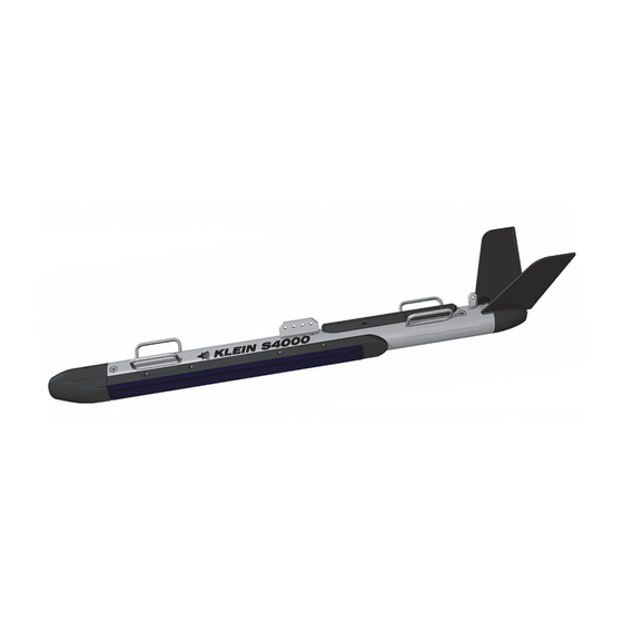
Stabilizing fins Safety cable tab Tow bracket Carrying handle (4) Tail cone Stainless steel housing Port transducer Nose cone Figure 1-1: Series 4000 Towfish... -
Page 20: Figure 1-2: Series 4000 Sonar System Topside System Main Components
CHAPTER 1 Overview Transceiver and Processing Unit (TPU) SonarPro Workstation Series 4000 Sonar System Topside System Main Components Figure 1-2: Series 4000 Sonar System Operations and Maintenance Manual P/N 11210094, Rev. 01... -
Page 21: Tpu
System Components 1.2.2 The TPU is housed in a 19-inch rack mountable 2U chassis and connects to the towfish directly using an optional coaxial tow cable, or to an optionally supplied winch using the supplied deck cable, where the winch connects to the towfish using a tow cable. -
Page 22: Splashproof Transceiver And Processing Unit
CHAPTER 1 Overview 1.2.4 Splashproof Transceiver and Processing Unit (SP-III TPU) The SP-III TPU, which is shown in Figure 1-3, is built into a rugged, lightweight splashproof case, and similar to the rack mountable TPU, it contains the electronics for powering the towfish, downlink multiplexing the control signals to the towfish,... - Page 23 CHAPTER 2: S PECIFICATIONS This chapter includes the physical and performance specifications for the main components of the Series 4000 Sonar System. NOTE Specifications are typical and subject to change without notice. General 1 port and 1 starboard Beams: Sonar channels: 100 kHz and 400 kHz;...
-
Page 24: Chapter 2 Specifications
CHAPTER 2 Specifications Topside System The main topside components of the Series 4000 Sonar System are the Transceiver and Processing Unit (TPU) and the SonarPro Workstation. Optionally available are the Splashproof Transceiver and Processing Unit (SP-III TPU) and the laptop computer. -
Page 25: Sp-Iii Tpu
Towfish 2.2.4 SP-III TPU 50.24 cm (19.78 in.) wide Size: 17.1 cm (6.72 in.) high 32.7 cm (12.89 in.) deep 6.8 kg (15.0 lb) Weight: Designed to IP-65 Ingress protection: 100BaseTx, Ethernet LAN, optional Outputs: wireless LAN, RS-232 serial ports (2) Selectable Sonar Data Format (SDF), Output data format: Extended Triton Format (XTF), or both... -
Page 26: External Sensor Pack
CHAPTER 2 Specifications 2.3.2 External Sensor Pack The External Sensor Pack (ESP) contains a compass, a pressure sensor and a temperature sensor. ±0.5∞ RMS Heading accuracy, level: ±1.0∞ RMS, <±30∞ tilt Heading accuracy, tilted: ±1.5∞ RMS, ±30∞ to ±60∞ tilt 0.1∞... -
Page 27: Armored Coaxial Tow Cable (0.40-Inch)
Tow Cables 2.4.2 Armored Coaxial Tow Cable (0.40-inch) Double layer, counter helical, galvanized Type: improved plow steel (GIPS) Coaxial copper Conductors: 10.2 mm (0.40 in.) Diameter (OD): 48.9 kN (11,000 lbf) Breaking strength: 12.2 kN (2750 lbf) Working load: 3000 m (9843 ft) maximum Operational length: 1200 VDC Voltage rating:... -
Page 29: Chapter 3: Setup And Test
If any items are damaged or missing, immediately contact Klein Marine Systems, Inc. or your KMS sales representative. In addition, record the serial numbers for the towfish, the TPU or SP-III TPU, and the SonarPro Workstation or laptop. -
Page 30: Locating The Topside System Components
CHAPTER 3 Setup and Test Locating the Topside System Components The TPU or SP-III TPU and the SonarPro Workstation or laptop computer should be located in an area that is protected from weather and spray and where the temperatures are consistently between 0°C and 35°C (32°F and 95°F). The SP-III TPU is partially sealed against spray and inclement weather. -
Page 31: Grounding
Towfish Setup 3.3.1 Grounding It is important that the Series 4000 Sonar System be well grounded to minimize potential hazards to the operator and electrical interference from other equipment. A good ground for the system is a low impedance, well conducted path to sea water. - Page 32 CHAPTER 3 Setup and Test Kellems grip Cable tie Tow cable Tow bracket Shackle Jumper cable Cable tie Tow Cable Termination at Towfish Figure 3-1: NOTE The safety cable must be taut enough so that drag, or the likelihood of snagging, is not increased, but loose enough so that it does not interfere with the rotation of the shackle.
-
Page 33: Connecting The Tow Cable With The Optionalk-Wing I Or K-Wing Ii Depressor
Towfish Setup 3.4.3 Connecting the Tow Cable with the Optional K-Wing I or K-Wing II Depressor The shackle on the tow cable connects mechanically to the towfish K-Wing I or K-Wing II depressor tow bracket using a tow pin. The depressor connects mechanically to the towfish. -
Page 34: Disconnecting The Tow Cable From The Towfish
CHAPTER 3 Setup and Test When using the safety cable, attach it to the loop of the Kellems grip and to the safety cable tab on the top of the towfish near the tail. Refer to Figure 1-1 on page 1-3 for the location of the safety cable tab. Secure the tow cable jumper with cable ties to the top of the towfish. -
Page 35: Figure 3-2: Tpu Back Panel
LAN connector TRIG A connector T/F TRIG connector AC INPUT connector TOWFISH connector NAV connector 1 PPS IN connector NOTE: Connectors that are not called out are not used or are for factory use only. Figure 3-2: TPU Back Panel... - Page 36 CHAPTER 3 Setup and Test The TPU connectors are the following: RJ-45 connector that connects to the ETHERNET ETHERNET: connector on the SonarPro Workstation. DB9 male RS-232 serial port connector that is for COM A: factory use only. DB9 male RS-232 serial port connector that is COM B: available as a spare and is not used.
-
Page 37: Sonarpro Workstation Connections
Topside System Connections 3.5.2 SonarPro Workstation Connections All the connections to the SonarPro Workstation are made to connectors on the back panel which is shown in Figure 3-3. The SonarPro Workstation connectors are the following: USB connectors (4, plus 2 on the front panel). Any USB: two connect to the keyboard and the mouse. -
Page 38: Figure 3-3: Sonarpro Workstation Back Panel
AC INPUT connector ON/OFF switch DVI connector ETHERNET connector (2) and circuit breaker USB connector (4) NOTE: Connectors that are not called out are not used or are available for optional use. Figure 3-3: SonarPro Workstation Back Panel... -
Page 39: Figure 3-4: Tpu-Iii Tpu Side Panel
D/C POLARITY NAV connector indicator T/F TRIG indicator LOCK LOSS DEBUG connector indicator T/F PWR RESP TRIG indicator MAG connector indicator indicator TOWFISH D/C-A/C connector switch RESP TRIG 12 VDC 120/240 VAC connector connector connector connector T/F TRIG EXT TRIG IN 1PPS connector connector... -
Page 40: Connecting The Topside System Components
3-12 CHAPTER 3 Setup and Test DB9 female connector that connects to a serial port DEBUG: of a computer and is available for factory use and troubleshooting purposes. The baud rate is 9600. DB9 female connector that is used to input NAV: navigation data. - Page 41 3-13 Connecting the Topside System Components Connect the keyboard and the mouse to any two of the six USB connectors on the SonarPro Workstation. Connect a GPS to the NAV connector on the TPU. A user supplied RS-232 serial cable is required where one end is terminated with a DB9 female connector and the other end is as required by the navigation system.
-
Page 42: Connecting The Sp-Iii Tpu And The Laptop Computer
3-14 CHAPTER 3 Setup and Test 3.6.2 Connecting the SP-III TPU and the Laptop Computer The following supplied cables are used to connect the SP-III TPU and the laptop computer: • Ethernet crossover cable • DC power cable • AC power cable •... -
Page 43: Table 3-3: Lan Connector Pinouts
12 VDC Table 3-3: Table 3-4: Connector Pinouts Connector Pinouts FUNCTION FUNCTION Return +12 VDC 120/240 VAC TOWFISH Table 3-5: Table 3-6: Connector Pinouts Connector Pinouts FUNCTION FUNCTION Neutral 200 VDC Power and Telemetry Shield Line Table 3-7: NAV, DEBUG Table 3-8: T/F TRIG, and MAG Connector... - Page 44 3-16 CHAPTER 3 Setup and Test Verify that the GPS is outputting NMEA-0183 formatted data strings at 4800 baud, no parity, 8 data bits, and 1 stop bit. In addition, the GPS should be outputting the following messages: • GLL or GGA •...
-
Page 45: Topside System Controls And Indicators
3-17 Topside System Controls and Indicators Topside System Controls and Indicators The TPU and the SonarPro Workstation include controls and indicators on the front panels. The SonarPro Workstation also has its power switch on the back panel. 3.7.1 TPU Controls and Indicators All of the TPU controls and indicators are on the TPU front panel which is shown in Figure 3-5. -
Page 46: Figure 3-5: Tpu Front Panel
TOWFISH indicators STATUS indicators POWER indicator POWER switch EQUALIZATION indicators SYS READY indicator OPTIONS indicators T/F POWER indicator Figure 3-5: TPU Front Panel... -
Page 47: Sonarpro Workstation Controls And Indicators
3-19 Topside System Controls and Indicators Yellow LED that flashes when the sonar on the STATUS TRIGGER: towfish transmits. Green LED that is on when internal system tests are STATUS TEST MODE: being performed. Blue LED that is on when power is applied to STATUS AUX: optional components. -
Page 48: Figure 3-6: Sonarpro Workstation Front Panel
HARD DRIVE ACTIVITY indicator ETHERNET indicator POWER ON indicator DVDRW optical drive RESET switch POWER switch USB connector (2) Figure 3-6: SonarPro Workstation Front Panel... -
Page 49: Sp-Iii Tpu Controls And Indicators
3-21 System Activation and Test 3.7.3 SP-III TPU Controls and Indicators All of the controls and indicators are located on the side panel of the SP-III TPU as shown in Figure 3-4 on page 3-11. They are the following: PWR: Green indicator that is illuminated when either AC or DC power is on. - Page 50 3-22 CHAPTER 3 Setup and Test Turn on the SonarPro Workstation or the laptop computer and wait for the Windows desktop to appear. NOTE For the SP-III TPU, should the DC power cable be connected with the polarities reversed, the D/C POLARITY indicator will illuminate when the A/C-D/C switch is switched to D/C.
-
Page 51: Activating And Testing The System At Sea
3-23 System Activation and Test Perform a rub test on the port and starboard transducers to confirm that the receivers are operating properly. Do this test by vigorously rubbing each transducer, one at a time, while observing the Sonar Viewer window in SonarPro for returns. - Page 52 3-24 CHAPTER 3 Setup and Test CAUTION Serious damage to the towfish electronics may occur if the towfish is operated on deck for periods longer than fifteen minutes. Between periods of operation, let the sonar cool for fifteen minutes. In high temperature climates, protect the towfish from direct exposure to the sun prior to and during operation.
-
Page 53: Chapter 4: Equipment Maintenance
CHAPTER 4: E QUIPMENT AINTENANCE This chapter provides instructions for maintaining the Series 4000 Sonar System on a daily, weekly and long term basis. In addition, instructions are provided for disassembling and reassembling the towfish and removing and installing the transducers. -
Page 54: Weekly Maintenance Checklist
CHAPTER 4 Equipment Maintenance Keep the tow cable plugged into the towfish, or use dummy plugs on the tow cable and towfish to keep the connectors from exposure to the salt atmosphere. Remember to put a thin film of silicone grease, such as Dow-Corning 4, on the rubber portion of the underwater connector every time the towfish is disconnected. -
Page 55: Disassembling And Reassembling The Towfish
Disassembling and Reassembling the Towfish Disassembling and Reassembling the Towfish For troubleshooting purposes and for repair, it may be required to remove and replace major components of the towfish. Instructions are provided in the following pages for the disassembly of the towfish and the removal of the towfish electronics chassis and the transducers. -
Page 56: Figure 4-2: Removing The Tail Cone
CHAPTER 4 Equipment Maintenance Pull the tail cone away Jumper cable from the towfish housing, and then reach inside the housing and disconnect the jumper and compass cables. Compass cable Removing the Tail Cone Figure 4-2: Set the tail cone aside, and then remove the tail cone retaining bolt which is shown in Figure 4-3. - Page 57 Disassembling and Reassembling the Towfish Using the 8-mm hex key, loosen the nose cone retaining bolt and remove the nose cone. The bolt is accessed from the tip of the nose. Removing the Nose Cone Figure 4-4: Disconnect the two transducer cables.
- Page 58 CHAPTER 4 Equipment Maintenance Using the 5-mm hex key, tighten the three locking screws in the towfish housing forward end cap. Locking screw (3) Tightening the Locking Screws in Figure 4-6: the Towfish Housing Forward End Cap Screw the tail cone retaining bolt into the threaded hole in the middle of the forward end...
-
Page 59: Figure 4-8: Pulling The Forward End Cap Out Of The Towfish Housing
Disassembling and Reassembling the Towfish Grasp the tail cone retaining bolt and carefully pull the forward end cap out of the towfish housing. Pulling the Forward End Cap out of Figure 4-8: the Towfish Housing Set the forward end cap aside as shown in Figure 4-9. -
Page 60: Figure 4-10: Tightening The Locking Screws In The Towfish Housing Aft End Cap
CHAPTER 4 Equipment Maintenance Using the 5-mm hex key, tighten the three locking screws in the towfish housing aft end cap. Locking screw (3) Tightening the Locking Screws in Figure 4-10: the Towfish Housing Aft End Cap Screw the tail cone retaining bolt into the threaded hole in the middle of the aft end cap. -
Page 61: Reassembling The Towfish
Disassembling and Reassembling the Towfish 4.3.2 Reassembling the Towfish To reassemble the towfish: Verify that the O-rings on both the forward and aft end caps are clean and free of dirt or scratches. Also use a lint-free cloth or paper towel to clean the O-ring surfaces inside the towfish housing and apply a light coat of silicone grease to these surfaces. - Page 62 4-10 CHAPTER 4 Equipment Maintenance Aligning the Locking Screws Figure 4-13: before Inserting the Forward End Cap Slide the nose cone into the towfish housing, aligning Slot the locator pin on the nose Locator pin cone with the slot in the housing and threading the nose cone retaining bolt into the forward end cap as...
-
Page 63: Removing The Transducers
4-11 Disassembling and Reassembling the Towfish 4.3.3 Removing the Transducers To remove the transducers: Perform Steps 1 through 4 in “Disassembling the Towfish” on page 4-3. Using the 4-mm hex key, remove the eight socket head cap screws securing either transducer assembly to the towfish housing. - Page 64 4-12 CHAPTER 4 Equipment Maintenance Set the transducer assembly down with the transducer facing up. Using the 4-mm hex key, remove the four socket head cap screws on the face of the transducer, two on each end. Socket head cap screw (2 each end) Location of the Four Socket Head Figure 4-17:...
-
Page 65: Installing The Transducers
4-13 Disassembling and Reassembling the Towfish 4.3.4 Installing the Transducers To install the transducers: Reverse Steps 2 through 7 in “Removing the Transducers” on page 4-11 for each transducer. Connect the two transducer cables, matching the colors with the connectors on the forward end cap. -
Page 67: Chapter 5: Technical Description
CHAPTER 5: T ECHNICAL ESCRIPTION This chapter provides an overall technical description of the Series 4000 Sonar System towfish, TPU and SP-III TPU electronics. This information, which includes block diagrams, printed circuit board descriptions, and chassis photos with callouts, is useful when performing any troubleshooting tasks and when installing optional equipment. -
Page 68: Figure 5-1: The Series 4000 Sonar System Towfish Electronics Block Diagram
Figure 5-1: The Series 4000 Sonar System Towfish Electronics Block Diagram... - Page 69 Subsea Telemetry 24 VDC Power Transmitter board board Supply and Filter board 12 VDC Power Supply and Filter board Transition board Control Sensor Interface (CSI) Receiver board board Figure 5-2: The Series 4000 Sonar System Towfish Electronics Chassis...
- Page 70 CHAPTER 5 Technical Description The CSI board interconnects the Control Sensor Interface (CSI) board. Transmitter board, the Receiver board, the Telemetry board, the sensors, and the ASCII I/O ports. Specifically, the CSI board performs the following functions: • Provides a central connection point for various system command interconnects.
-
Page 71: Transducer Arrays
Towfish The Transition board provides the means to connect the Transition board. large gauge wires from the RX PORT and RX STBD bulkhead connectors on the end cap to the Receiver board’s 50 pin ribbon cable and to the Transmitter board’s 3-pin connectors. -
Page 72: Tpu
CHAPTER 5 Technical Description A block diagram depicting the functional relationships of all of the printed circuit boards in the TPU electronics is shown in Figure 5-3. These boards are located in the TPU electronics chassis as shown in Figure 5-4. The printed circuit boards, along with their corresponding part numbers, are the following: •... -
Page 73: Figure 5-3: The Series 4000 Sonar System Tpu Electronics Block Diagram
Figure 5-3: The Series 4000 Sonar System TPU Electronics Block Diagram... -
Page 74: Figure 5-4: The Series 4000 Sonar System Tpu Electronics Chassis
CPU board 200V Power Filter board Demultiplexer board 12V Power Filter board 12V Power Supply board Topside Telemetry board High Voltage LED board Power Supply board Figure 5-4: The Series 4000 Sonar System TPU Electronics Chassis... -
Page 75: Sp-Iii Tpu
SP-III TPU The Topside Telemetry board provides the cable Topside Telemetry board. interface for the TPU. Specifically, the Topside Telemetry board performs the following functions: • Separates the uplink data signals, the downlink command signals and the towfish power. • Acquires sonar and sensor data and reformats the data as required for the Demultiplexer board. -
Page 76: Figure 5-5: The Series 4000 Sonar System Sp-Iii Tpu Electronics Block Diagram
Figure 5-5: The Series 4000 Sonar System SP-III TPU Electronics Block Diagram... -
Page 77: Figure 5-6: The Series 4000 Sonar System Sp-Iii Tpu Electronics Chassis
Panel Interconnect board Power Integration 12 VDC board power supply CPU board (under Telemetry CDI board board) Topside Telemetry board (under Telemetry board) Figure 5-6: The Series 4000 Sonar System SP-III TPU Electronics Chassis... - Page 78 5-12 CHAPTER 5 Technical Description The CPU board functions as the command and data interface CPU board. between the laptop computer running SonarPro and the tow fish. It executes a real-time data server which outputs sonar and sensor data to and receives commands from an external client, such as SonarPro The Topside Telemetry board provides the cable Topside Telemetry board.
-
Page 79: Appendix A: Notes On Handling Tow Cables
APPENDIX A: N OTES ON ANDLING ABLES A few methods on how to safely unreel tow cables are provided in this appendix. In addition, how cable kinking can occur is identified along with what can result from this condition. A.1 Unreeling Tow Cable The reel should be revolved and the rope taken off the way it was put on the reel as shown in Figure A-1 for two effective methods. -
Page 80: A.2 Uncoiling Tow Cable
APPENDIX A Notes on Handling Tow Cables A.2 Uncoiling Tow Cable Remove ties and roll the coil along the ground so the rope lies straight. There will be no twist or kink in the cable if these instructions are followed. CAUTION If the reel and coil do not revolve freely, it will cause the cable to twist as each turn is taken off. -
Page 81: A.3.2 Effect Of Cable Kinking
Cable Kinking Cable Loop Cable Kink Cable Loop and Kink Figure A-3: A.3.2 Effect of Cable Kinking The effect of kinking is shown in Figure A-4. The cable is permanently damaged Damaged Cable Figure A-4: A.3.3 Result of Cable Kinking The result of cable kinking is that strands and wires are displaced, creating uneven tension which causes excessive wear at the point of the kink. -
Page 83: Appendix B: Configuring And Updating The Tpu/Sp-Iii Tpu
B.1 Starting Linux TPU/SP-III TPU Updater Linux TPU/SP-III TPU Updater is started by double-clicking the Linux TPU Updater icon on the Windows desktop. The Klein Linux TPU Updater dialog box will open as shown Figure B-1. The Klein Linux TPU Updater Dialog Box... -
Page 84: Querying Or Changing The Tpu/Sp-Iii Tpu Ip Address
7. From the Rate drop-down list box, select the baud rate of the TPU/SP-III TPU’s NAV serial port, or select Determine Automatically to have Linux TPU Updater find the rate. The Klein Linux TPU Updater dialog box opens with the current IP address displayed in the text box as shown in Figure B-3. -
Page 85: B.3 Editing The Tpu/Sp-Iii Tpu Startup File
Editing the TPU/SP-III TPU Startup File The Klein Linux TPU Updater Dialog Box with Current TPU/SP-III Figure B-3: TPU IP Address Displayed 8. Enter the new address in the Enter New IP Address text box, and then click Set TPU IP Address A window opens confirming the change: B.3 Editing the TPU/SP-III TPU Startup File... -
Page 86: B.4 Updating The Tpu/Sp-Iii Tpu Software
3. Turn on the TPU, or turn on the SP-III TPU by switching the A/C-D/C switch to A/C for AC operation or to D/C for DC operation. 4. Start Linux TPU Updater. The Klein Linux TPU Updater dialog box opens. Series 4000 Sonar System Operations and Maintenance Manual P/N 11210094, Rev. 01... - Page 87 Updating the TPU/SP-III TPU Software TPU/SP-III TPU IP address in the 5. Enter the text box if it Enter TPU IP Address is different than the default address, or click if it is the default. The Default Addr default address is 192.168.0.81. The address will already be displayed if it was queried or changed as described in “Querying or Changing the TPU/SP-III TPU IP Address”...
-
Page 89: Appendix C: Drawings
APPENDIX C: D RAWINGS This appendix includes the following outline drawings. They are provided for reference purposes. Outline, Rackmount TPU Drawing 14605729: Outline, Splashproof III Drawing 14605659: Outline Drawing S4000 Towfish Drawing 14605818:... -
Page 93: Appendix D: Towfish Towing Characteristics
APPENDIX D: T OWFISH OWING HARACTERISTICS This appendix describes the towing characteristics of the towfish as graphical plots of the towfish depth versus tow cable length for various towfish speeds. - Page 94 APPENDIX D Towfish Towing Characteristics Series 4000 Sonar System Operations and Maintenance Manual P/N 11210094, Rev. 01...
- Page 96 APPENDIX D Towfish Towing Characteristics Series 4000 Sonar System Operations and Maintenance Manual P/N 11210094, Rev. 01...
- Page 98 APPENDIX D Towfish Towing Characteristics Series 4000 Sonar System Operations and Maintenance Manual P/N 11210094, Rev. 01...
Need help?
Do you have a question about the 4000 Series and is the answer not in the manual?
Questions and answers