
Related Manuals for Klein 5000 V2 Series


Summary of Contents for Klein 5000 V2 Series
- Page 1 5000 V2 S ERIES ONAR YSTEM Operations and Maintenance Manual P/N 11214512, Rev. 04 11 Klein Drive Salem, NH 03079-1249 U.S.A. Tel: (603) 893-6131 Fax: (603) 893-8807 www.KleinMarineSystems.com...
- Page 2 This document contains proprietary information, and such information may not be disclosed to others for any purpose or used for any manufacturing purpose without expressed written permission from Klein Marine Systems, Inc. (KMS). The information provided is for informational purposes only and is subject to change without notice.
- Page 3 WARNING Klein Marine Systems, Inc. recommends all troubleshooting be done by a trained technician. Some circuits in the Sonar Transceiver and Processing Unit have voltages as high as 240 volts, and some circuits in the sonar towfish have 1500 volts. You should familiarize yourself with the location of these voltages before you attempt any troubleshooting.
-
Page 4: Table Of Contents
Table of Contents Table of Contents ..........iv List of Figures . - Page 5 2.3.6 Multiplexer ........2-4 2.3.7 Power .
- Page 6 CHAPTER 4: Maintenance and Troubleshooting ....4-1 General Maintenance Recommendations ....4-1 Maintenance Checklists .
- Page 7 APPENDIX C: Configuring and Updating the TPU ... . . C-1 Starting Linux TPU Updater ......C-1 Querying or Changing the TPU IP Address .
-
Page 8: List Of Figures
viii List of Figures Figure 1-1: Series 5000 Towfish ......... . . 1-3 Figure 1-2: Series 5000 V2 Sonar System Topside System Main Components . - Page 9 Damaged Cable ..........B-3 Figure C-1: The Klein Linux TPU Updater Dialog Box ......C-1 Figure C-2: The Select RS-232 Port Dialog Box.
-
Page 10: List Of Tables
List of Tables Table 3-1: TPU Power Cable Wiring ......... 3-2 Table E-1: List of Drawings and Parts Lists . -
Page 11: Sonar System Warranty
Sonar System Warranty What Is Covered LIMITED WARRANTY Subject to the conditions set forth below, equipment sold by Seller is warranted against defects in materials and workmanship, and Seller will repair or exchange any parts proven to be malfunctioning under normal use for one year (12 months) from the date of Delivery as follows: a) SONAR and other associated manufactured products, with the following exceptions:... -
Page 12: Conditions Of Warranty
Conditions Of Warranty a) Seller’s warranty policy does not apply to equipment which has been subjected to accident, abuse, or misuse, shipping damage, alterations, incorrect and/or non- authorized service or equipment on which the serial number plate has been altered, mutilated or removed. b) A suitable proof of purchase, such as, a paid commercial invoice, an installation certificate signed by Seller or an authorized agent must be made available to Seller or Seller’s authorized servicing agent at the time of the Warranty Service. -
Page 13: Changes, Errors And Omissions
AROSE. Changes, Errors And Omissions Klein Marine Systems, Inc. reserves the right to make changes to the design or specifications at any time without incurring any obligation to modify previously delivered sonar systems. In addition, while considerable effort has been made to ensure that the information in this manual is accurate and complete, Klein Marine Systems, Inc. -
Page 14: Software License Agreement
Software License Agreement This Software License Agreement is provided by Klein Marine Systems, Inc. © (KMS) for end users of SonarPro software for the KMS Series 3000, UUV-3500, 3900, 4900, 5000, 5000 V2, 5900, HydroChart 3500, HydroChart 5000, and D3500TF Sonar Systems. - Page 15 BATHYMETRIC PROCESSING ATTRIBUTION: Bathymetric processing derived from DGA/GESMA publication in IEEE OCEAN'S 05 Europe Conference Proceedings: "Bathymetric Sidescan Sonar: a System Dedicated to Rapid Environment assessment, ref: 10.1109/OCEANSE.2005.1511695. EXPORT RESTRICTIONS: You agree that you will not export or re-export the Software or accompanying documentation (or any copies thereof) or any products utilizing the Software or such documentation in violation of any applicable laws or regulations of the United States or the country in which you obtained them.
-
Page 16: Preface
ENTIRE AGREEMENT: This License Agreement sets forth the entire understanding and agreement between you and KMS supersedes all prior agreements, whether written or oral, with respect to the Software, and may be amended only in a writing signed by both parties. Preface The Series 5000 V2 Sonar System is a towed multibeam sonar comprising a towed underwater platform and a topside system. -
Page 17: Note, Warning, Caution, And Shock Hazard Notices
xvii Appendix C: Configuring and Updating the TPU. Provides instructions on how to configure and update the Series 5000 V2 Sonar System TPU. Appendix D: Different Tow Cable Lengths and the Startup.ini File. Provides instructions on how to tune the Series 5000 V2 Sonar system for optimum performance versus various cable lengths and how to measure cable insertion loss. -
Page 18: Customer Service
Customer Service KMS technical support can be contacted using any of the following means: Mail Klein Marine Systems, Inc. 11 Klein Drive Salem, NH 03079 Email TechSupport@KleinMarineSystems.com Telephone (603) 893-6131 Facsimile (603) 893-8807 For more information about KMS and our products, please go to our Web site at www.KleinMarineSystems.com... -
Page 19: Chapter 1: Overview
CHAPTER 1: O VERVIEW The Series 5000 V2 Sonar System is a very high resolution, multibeam long range sonar system that is ideally suited for surface mine counter measure applications and hydrographic, geophysical, pipeline, and offshore surveys. The two primary drawbacks of conventional side-looking sonars, along-track resolution and towing speed limitation, have been addressed by simultaneously forming multiple dynamically focused beams per side, per ping. -
Page 20: System Components
CHAPTER 1 Overview System Components The main components of the Series 5000 V2 Sonar System are the towfish and the topside system. The towfish is the underwater component and is towed with an armored coaxial tow cable up to 800 meters in length. The topside system provides the power source for the towfish and receives, stores and processes data acquired by the towfish. -
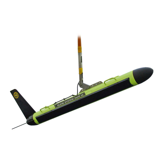
Page 21: Figure 1-1: Series 5000 Towfish
Tow bracket Nose cone Carrying handle (4) Safety cable Safety cable Stainless steel towfish housing Stabilizing fins Starboard transducer array Altimeter Tail cone Figure 1-1: Series 5000 Towfish... -
Page 22: Figure 1-2: Series 5000 V2 Sonar System Topside System Main Components
CHAPTER 1 Overview Transceiver and Processing Unit (TPU) SonarPro Workstation Figure 1-2: Series 5000 V2 Sonar System Topside System Main Components Series 5000 V2 Sonar System Operations and Maintenance Manual P/N 11214512, Rev. 04... -
Page 23: Sonarpro Workstation
System Components commands to the towfish by combining 200 VDC with FSK control signals for transmission over the coaxial conductor in the tow cable. In addition, the TPU initiates each ping cycle to the side scan sonar and provides a trigger signal simultaneously with the responder trigger generated in the towfish for use with an acoustic positioning system. - Page 25 CHAPTER 2: S PECIFICATIONS This chapter includes the physical and performance specifications for the main components of the Series 5000 V2 Sonar System. NOTE Specifications are typical and subject to change without notice. Sonar System Beams: 5 port and 5 starboard Sonar frequency: 455 kHz Maximum range:...
-
Page 26: Chapter 2 Specifications
CHAPTER 2 Specifications Topside System The main topside components of the Series 5000 V2 Sonar System are the Transceiver and Processing Unit (TPU) and the SonarPro Workstation. 2.2.1 System Power Requirements The system power requirements are 100–125 or 200–250 VAC, 50–60 Hz at 100 watts for the TPU and the towfish together. -
Page 27: Towfish
Towfish Monitor: 27-inch diagonal 2560 x 1440 resolution 16:9 aspect ratio Operator I/O: Keyboard and mouse Towfish 2.3.1 General Body material: Type 316 stainless steel Nose/tail cone material: Urethane (80 D Durometer) Tail fin material: Hard-coat anodized 6061 aluminum Size: 203 cm (79.9 in.) long 16.8 cm (6.6 in.) diameter 30.5 cm (24 in.) wide, including tail fins... -
Page 28: A/D Converter
CHAPTER 2 Specifications 2.3.5 A/D Converter Type: Pipeline Resolution: 14 bits Quantization: Linear Sample rate: Proprietary 2.3.6 Multiplexer Modulation format: Pulse code modulation (PCM) Multiplexing format: Time division multiplexing (TDM) Number of channels: Data rate: 29.12 Mbaud Data format: Bit error rate: Better than 1x10 (before correction) 2.3.7... -
Page 29: Tow Cables
Tow Cables Tow Cables Electrically, the tow cable must be 50 ohms. The whole cable assembly, including the deck cable, the slip rings, the winch, the tow cable, and the connectors must be coax all the way from the TPU to the towfish. 2.4.1 Lightweight Coaxial Deck Cable Type:... -
Page 30: Towfish Options
CHAPTER 2 Specifications Operational length (including deck cable): 750 m max Voltage rating: 3000 VDC Termination: Stainless steel shackle at towfish end Towfish Options The towfish can be equipped with the following options: • Responder interface • Transponder interface • Magnetometer interface •... -
Page 31: Chapter 3: Preparation For Use
If any items are damaged or missing, immediately contact Klein Marine Systems, Inc. or your KMS sales representative. In addition, record the serial numbers for the towfish, the TPU and the SonarPro Workstation. -
Page 32: Grounding
CHAPTER 3 Preparation for Use CAUTION Application of improper AC power may damage the Series 5000 V2 Sonar System. Do not turn the equipment on until the supply voltage and frequency have been checked. Since a variety of power connectors are in use throughout the world, it may be necessary to use an adapter or to cut off the US-type plug on the AC power cable and re-terminate it with a new plug. -
Page 33: Connecting The Tow Cable
Towfish Setup 3.4.1 Connecting the Tow Cable WARNING Before connecting the tow cable, verify that the power to the TPU is turned off. Also disconnect the TPU power cable from the power source. Failure to follow this practice may result in personal injury or damage to the towfish or the TPU electronics, or to both. -
Page 34: Connecting The Tow Cable With The Optional K-Wing
CHAPTER 3 Preparation for Use Attach the shackle end of the safety cable to the bail grip loop on the tow cable near the tow cable shackle, and the clevis pin end to the safety cable tab on the top of the towfish near the tail. Refer to Figure 1-1 on page 1-3 for the location of the safety cable tab. -
Page 35: Disconnecting The Tow Cable From The Towfish
If the tow cable is disconnected, however, it is very important that all the connectors be properly maintained. Connectors must be kept clean and must remain out of the way of traffic while on deck. Klein Marine Systems, Inc. supplies dummy connectors which can be used to protect the underwater connectors on the towfish and cable when they are not mated to each other. -
Page 36: Topside System Connections
CHAPTER 3 Preparation for Use To disconnect the tow cable: Verify that the TPU is switched off and that its power cord is disconnected. Disconnect the safety cable from the bail grip loop. Remove the electrical tape securing the safety cable to the tow cable. Cable ties fastening the safety cable to the cable hold-down clips on the towfish housing may remain in place. -
Page 37: Figure 3-1: Tpu Back Panel
LAN connector TRIG A connector T/F TRIG connector AC INPUT connector TOWFISH connector NAV connector 1 PPS IN connector NOTE: Connectors that are not called out are not used or are for factory use only. Figure 3-1: TPU Back Panel... -
Page 38: Sonarpro Workstation Connections
CHAPTER 3 Preparation for Use T/F TRIG: BNC connector that connects to an external sonar system and is used to trigger the sonar of that system at the start of each ping cycle. Provides a TTL compatible, 100-µs wide output pulse. TRIG A: BNC connector that connects to an ultra short baseline navigation system (USBL). -
Page 39: Figure 3-2: Sonarpro Workstation Back Panel
AC INPUT connector ON/OFF switch DVI connector ETHERNET connector (2) and circuit breaker USB connector (4) NOTE: Connectors that are not called out are not used or are available for optional use. Figure 3-2: SonarPro Workstation Back Panel... -
Page 40: Connecting The Topside System Components
3-10 CHAPTER 3 Preparation for Use Connecting the Topside System Components The following cables are required to connect the TPU and the SonarPro Workstation: • Ethernet cable • AC power cords (2) • Deck cable or tow cable (deck cable is optionally supplied) WARNING Before connecting the topside system components, verify that the TPU is turned off and that its power cord is disconnected. -
Page 41: Topside System Controls And Indicators
3-11 Topside System Controls and Indicators Connect the optional deck cable or tow cable to the TOWFISH connector on the TPU. NOTE For the predeployment checks, the optional deck cable can be temporarily connected to the TOWFISH connector on the TPU and to the towfish. -
Page 42: Figure 3-3: Tpu Front Panel
TOWFISH indicators STATUS indicators POWER indicator POWER switch SYS READY indicator T/F POWER indicator NOTE: Indicators that are not called out are not used or are available for optional use. Figure 3-3: TPU Front Panel... -
Page 43: Sonarpro Workstation Controls And Indicators
3-13 Topside System Controls and Indicators T/F POWER: Blue LED that is on when power is being applied to the towfish. TOWFISH AWAKE: Green LED that is on when the towfish is powered and is acquiring data. TOWFISH DOWNLINK: Green LED that is on when commands are being transfered from the TPU to the towfish. -
Page 44: Figure 3-4: Sonarpro Workstation Front Panel
HARD DRIVE ACTIVITY indicator ETHERNET indicator POWER ON indicator DVDRW optical drive RESET switch POWER switch USB connector (2) Figure 3-4: SonarPro Workstation Front Panel... -
Page 45: System Activation And Test
3-15 System Activation and Test System Activation and Test The Series 5000 V2 Sonar System should be activated and tested on deck and at sea before starting an actual survey. NOTE Should it be required to change the IP address, edit the startup.ini file or update the software of the TPU, refer to APPENDIX C: “Configuring and Updating the TPU.”... -
Page 46: Activating And Testing The System At Sea
3-16 CHAPTER 3 Preparation for Use Perform a rub test on the port and starboard transducers to confirm that the receivers are operating properly. Do this test by vigorously rubbing each transducer, one at a time, while observing the Sonar Viewer window in SonarPro for returns. - Page 47 3-17 System Activation and Test Adjust the towfish within the water column so that it is at a safe altitude off the bottom and under the boat wake (about 15 percent of range). A good starting vessel speed is 4–5 knots. Check for the following: •...
-
Page 49: Chapter 4: Maintenance And Troubleshooting
WARNING Klein Marine Systems, Inc. recommends all troubleshooting be done by a trained technician. Some circuits in the Sonar Transceiver and Processing Unit have voltages as high as 240 volts, and some circuits in the sonar towfish have 1500 volts. -
Page 50: Maintenance Checklists
CHAPTER 4 Maintenance and Troubleshooting Maintenance Checklists 4.2.1 Daily Maintenance Checklist Perform the following maintenance steps at the end of each day’s operation: Turn off the power to the TPU and to the SonarPro Workstation. 2. Verify that all cables and connectors are secure and tightened. 3. -
Page 51: Replacing The Fixed Tail Cone Assembly
Replacing the Fixed Tail Cone Assembly 2. Thoroughly clean the TPU, cables and towing equipment. Clean the top and outside surfaces of the TPU using a cloth dampened with fresh water. Use a small amount of detergent if necessary. Do not let dirt and salt deposits accumulate on the TPU cabinet. -
Page 52: Figure 4-2: Tail Cone Being Aligned And Attached To Towfish
CHAPTER 4 Maintenance and Troubleshooting With the large hole to the upper right, align the tail cone with the rear center pin and thread the rear tail cone bolt (7) into the rear center pin using the 8-mm hex key. Figure 4-2: Tail Cone being Aligned and Attached to Towfish... -
Page 53: Figure 4-4: Crossbar Used To Secure Tail Cone Parts
Replacing the Fixed Tail Cone Assembly 4. Install the crossbar (4) into the large hole. Figure 4-4: Crossbar Used to Secure Tail Cone Parts 5. Using the flat bladed screw driver, align the threaded hole in the crossbar (4) and screw the bolt (7) with the retaining cup (5) into the crossbar with the 8-mm hex... -
Page 54: Removing The Fixed Tail Cone Assembly
CHAPTER 4 Maintenance and Troubleshooting 6. Install the two horizontal tail fins (2) and the vertical tail fin (3) by inserting the forward slot into the towfish body. The rearward slot should be secured by the retaining cup. Figure 4-6: Tail Fins being Inserted into Tail Cone 7. -
Page 55: Removing The Towfish Electronics
Removing the Towfish Electronics Removing the Towfish Electronics To remove the towfish electronics: 1. Remove the towfish nose cone by unscrewing the socket head cap screw in the center with an 8-mm hex key or driver. Once you have the nose cone off you will find the push/pull assembly shown in Figure 4-8. -
Page 56: Installing The Towfish Electronics
CHAPTER 4 Maintenance and Troubleshooting Installing the Towfish Electronics To install the towfish electronics: 1. Slide the electronics gently and carefully into the pressure bottle, aligning the alignment pin with the notch in the pressure housing. 2. Locate the bulkhead connectors on the electronics housing end cap. -
Page 57: Testing The Towfish Electronics
Testing the Towfish Electronics 4. Position the post with the threaded hole to the top, and thread the jacking screw into the post with the long, unthreaded section entering the feed-thru. CAUTION When tightening the jacking screw as described below, do not over tighten. -
Page 58: Checking The Multiplexer Board
4-10 CHAPTER 4 Maintenance and Troubleshooting 4.7.1 Checking the Multiplexer Board The Multiplexer board is shown Figure 5-2 on page 5-3. When checking voltages, unless otherwise noted, use TPGND1 as the ground reference. Reference designations are printed on the board. To check the Multiplexer board, do the following: •... -
Page 59: Figure 4-13: Multiplexer Board Waveforms
4-11 Testing the Towfish Electronics TP18 Telemetry TP17 TP28 TVG curve Figure 4-13: Multiplexer Board Waveforms Figure 4-14: Sample Transmit Waveform... -
Page 60: Checking The Sensors
4-12 CHAPTER 4 Maintenance and Troubleshooting 4.7.4 Checking the Sensors Sensor readings can be read out directly in the Information window in SonarPro. Move the towfish in pitch, roll and heading and check to see if the readings change. If you have no sensor readings, check that the cable is properly plugged into the sensor interface board at JP5. - Page 61 4-13 Testing the Towfish Electronics NOTE Excellent calibration results have been obtained by enabling the compass calibration and towing the towfish in a series of three circles with the boat. NOTE If trying the method mentioned in the note above, survey the area first making sure you have enough water to operate safely since the transmitters are turned off.
-
Page 63: Chapter 5: Technical Description
CHAPTER 5: T ECHNICAL ESCRIPTION This chapter provides an overall technical description of the Series 5000 V2 Sonar System towfish and TPU electronics. This information, which includes block diagrams, printed circuit board descriptions, and chassis photos with callouts, is useful when performing any troubleshooting tasks and when installing optional equipment. -
Page 64: Figure 5-1: Towfish Block Diagram-12 Sidescan Channels And 3 Bathymetery
CHAPTER 5 Technical Description Figure 5-1: Towfish Block Diagram—12 Sidescan Channels and 3 Bathymetery Channels Transmitter board. The Transmitter board produces a transmit pulse, at the start of a swath, that ensonifies the sea floor over a defined footprint. The Transmitter board is composed of two individual transmitting channels, one connected to the port array and the other connected to the starboard array. - Page 65 Multiplexer board Power Supply Compass Receiver Sensor Interface board board board (2) board Transmitter board Figure 5-2: The Series 5000 V2 Sonar System TPU Electronics Chassis...
-
Page 66: Transducer Arrays
CHAPTER 5 Technical Description Multiplexer board. The Multiplexer board digitizes the signals from each of the transducer sub-array channels along with the signals from the sensors, encodes the data, and transmits a high baud rate digital data stream to the TPU by way of the tow cable. -
Page 67: Tpu
A block diagram depicting the functional relationships of all of the printed circuit boards in the TPU electronics is shown in Figure 5-3. These boards are located in the TPU electronics chassis as shown in Figure 5-4. The printed circuit boards, along with their corresponding part numbers, are the following: •... -
Page 68: Figure 5-3: The Series 5000 V2 Sonar System Tpu Electronics Block Diagram
Figure 5-3: The Series 5000 V2 Sonar System TPU Electronics Block Diagram... -
Page 69: Figure 5-4: The Series 5000 V2 Sonar System Tpu Electronics Chassis
200V Power Filter board CPU board Demultiplexer 12V Power board Filter board 12V Power Supply board Topside Telemetry board High Voltage LED board Power Supply board Figure 5-4: The Series 5000 V2 Sonar System TPU Electronics Chassis... - Page 70 CHAPTER 5 Technical Description Topside Telemetry board. The Topside Telemetry board provides the cable interface for the TPU. Specifically, the Topside Telemetry board performs the following functions: • Separates the uplink data signals, the downlink command signals and the towfish power. •...
-
Page 71: Appendix A: Sample Towing Characteristics
APPENDIX A: S AMPLE OWING HARACTERISTICS Five towing characteristic graphs are included in this appendix as Figure A-1 through Figure A-5. Two of the graphs were generated without any additional weight being added to the towfish, and the other two graphs were made with our K-Wing II Depressor attached to the towfish. - Page 72 More details on towing characteristics, such as tension, layback, etc., are available at Klein Marine Systems, Inc. We would be glad to help you meet your requirements. Your experiences in towing our side scan sonar under various conditions would be helpful in upgrading our data, and we respectfully solicit your comments.
-
Page 73: Figure A-1: Cable Length Vs. Towfish Depth Graph 1
Figure A-1: Cable Length vs. Towfish Depth Graph 1... -
Page 74: Figure A-2: Cable Length Vs. Towfish Depth Graph 2
Figure A-2: Cable Length vs. Towfish Depth Graph 2... -
Page 75: Figure A-3: Cable Length Vs. Towfish Depth Graph 3
Figure A-3: Cable Length vs. Towfish Depth Graph 3... -
Page 76: Figure A-4: Cable Length Vs. Towfish Depth Graph 4
Figure A-4: Cable Length vs. Towfish Depth Graph 4... -
Page 77: Figure A-5: Cable Length Vs. Towfish Depth Graph 5
Figure A-5: Cable Length vs. Towfish Depth Graph 5... -
Page 79: Appendix B: Notes On Handling Tow Cables
APPENDIX B: N OTES ON ANDLING ABLES A few methods on how to safely unreel tow cables are provided in this appendix. In addition, how cable kinking can occur is identified along with what can result from this condition. B.1 Unreeling Tow Cable The reel should be revolved and the rope taken off the way it was put on the reel as shown in Figure B-1 for two effective methods. -
Page 80: B.2 Uncoiling Tow Cable
APPENDIX B Notes on Handling Tow Cables B.2 Uncoiling Tow Cable Remove ties and roll the coil along the ground so the rope lies straight. There will be no twist or kink in the cable if these instructions are followed. CAUTION If the reel and coil do not revolve freely, it will cause the cable to twist as each turn is taken off. -
Page 81: B.3.2 Effect Of Cable Kinking
Cable Kinking Cable Loop Cable Kink Figure B-3: Cable Loop and Kink B.3.2 Effect of Cable Kinking The effect of kinking is shown in Figure B-4. The cable is permanently damaged Figure B-4: Damaged Cable B.3.3 Result of Cable Kinking The result of cable kinking is that strands and wires are displaced, creating uneven tension which causes excessive wear at the point of the kink. -
Page 83: C.1 Starting Linux Tpu Updater
C.1 Starting Linux TPU Updater Linux TPU Updater is started by double-clicking the Linux TPU Updater icon on the Windows desktop. The Klein Linux TPU Updater dialog box will open as shown Figure C-1. Figure C-1: The Klein Linux TPU Updater Dialog Box... -
Page 84: Appendix C Configuring And Updating The Tpu
7. From the Rate drop-down list box, select the baud rate of the TPU’s NAV serial port, or select Determine Automatically to have Linux TPU Updater find the rate. The Klein Linux TPU Updater dialog box opens with the current IP address displayed in the text box as shown in Figure C-3. -
Page 85: C.3 Editing The Tpu Startup File
Editing the TPU Startup File Figure C-3: The Klein Linux TPU Updater Dialog Box with Current TPU IP Address Displayed 8. Enter the new address in the Enter New IP Address text box, and then click Set TPU IP Address A window opens confirming the change: C.3 Editing the TPU Startup File... -
Page 86: C.4 Updating The Tpu Software
2. Turn on the SonarPro Workstation and wait for the Windows desktop to appear. 3. Turn on the TPU. 4. Start Linux TPU Updater. The Klein Linux TPU Updater dialog box opens. Series 5000 V2 Sonar System Operations and Maintenance Manual P/N 11214512, Rev. 04... - Page 87 Updating the TPU Software TPU IP address in the 5. Enter the text box if it is different Enter TPU IP Address than the default address, or click Default Addr if it is the default. The default address is 192.168.0.81. The address will already be displayed if it was queried or changed as described in “Querying or Changing the TPU IP Address”...
-
Page 89: File
APPENDIX D: D IFFERENT ABLE ENGTHS AND THE TARTUP The Series 5000 V2 Sonar System operates at high data rates. For optimum performance, settings have been provided to tune the system’s uplink for various cable lengths up to -24 dB of insertion loss. The adjustment settings are made in the Startup.ini file using the following two lines: set PREEMPHISIS x set LBOGAIN x... -
Page 90: D.1 Measuring Cable Insertion Loss
APPENDIX D Different Tow Cable Lengths and the Startup.ini File For example, when testing a 1000-meter cable, from SonarPro the following command set yielded error-free operation: $MG2 and $ML7. Therefore the Startup.ini file would be adjusted to contain the following: set PREEMPHISIS 7 set LBOGAIN 2 D.1 Measuring Cable Insertion Loss... -
Page 91: D.2 Spare Tow Cable
Spare Tow Cable 50 ohm terminator Function Cable Generator Assembly Scope Figure D-2: Setup for Measuring Tow Cable Characteristics using a Function Generator, Terminator and Oscilloscope Use the formula dB = 20 log (Vout /Vin) For example, if at 15 MHz, you get a reading of 160 mv, then dB = 20 log (0.16/1.0) = 15.9 dB loss. -
Page 93: Table E-1: List Of Drawings And Parts Lists
APPENDIX E: D RAWINGS AND ARTS ISTS Listed in Table E-1 are the drawings and parts lists included in this appendix. They are provided for reference and troubleshooting purposes. Each assembly drawing is followed by its corresponding parts list. Table E-1: List of Drawings and Parts Lists DRAWING PARTS... - Page 105 E-13...
- Page 107 E-15...
- Page 109 E-17...
-
Page 110: Appendix E Drawings And Parts Lists
E-18 APPENDIX E Drawings and Parts Lists Series 5000 V2 Sonar System Operations and Maintenance Manual P/N 11214512, Rev. 04... - Page 112 E-20 APPENDIX E Drawings and Parts Lists Series 5000 V2 Sonar System Operations and Maintenance Manual P/N 11214512, Rev. 04...
Need help?
Do you have a question about the 5000 V2 Series and is the answer not in the manual?
Questions and answers