
Subscribe to Our Youtube Channel
Related Manuals for Klein 3900 Series


Summary of Contents for Klein 3900 Series
- Page 1 3900 S ERIES ONAR YSTEM Operations and Maintenance Manual P/N 11210085, Rev. 01 11 Klein Drive Salem, NH 03079-1249 U.S.A. Tel: (603) 893-6131 Fax: (603) 893-8807 www.KleinMarineSystems.com...
- Page 2 This document contains proprietary information, and such information may not be disclosed to others for any purpose or used for any manufacturing purpose without expressed written permission from Klein Marine Systems, Inc. (KMS). The information provided is for informational purposes only and is subject to change without notice.
- Page 3 WARNING Klein Marine Systems recommends all troubleshooting be done by a trained technician. Some circuits in the Sonar Transceiver and Processing Unit have voltages as high as 240 volts, and some circuits in the sonar towfish have 1500 volts. You should familiarize yourself with the location of these voltages before you attempt any troubleshooting.
-
Page 4: Table Of Contents
Table of Contents Table of Contents ..........iv List of Figures . - Page 5 CHAPTER 2: Specifications ....... 2-1 Sonar System ........2-1 Splashproof-II Transceiver and Processing Unit .
- Page 6 3.7.1 Activating and Testing the System on Deck ... . 3-12 3.7.2 Activating and Testing the System at Sea ....3-13 CHAPTER 4: Equipment Maintenance .
-
Page 7: List Of Figures
Figure A-4: Figure B-1: The Klein Linux TPU Updater Dialog Box ......B-1 Figure B-2: The Select RS-232 Port Dialog Box....... B-2... - Page 8 viii List of Tables Table 3-1: SP-II TPU Power Cord Wiring ........3-2 Table 3-2: LAN Connector Pinouts .
-
Page 9: Sonar System Warranty
Sonar System Warranty What Is Covered LIMITED WARRANTY Subject to the conditions set forth below, equipment sold by Seller is warranted against defects in materials and workmanship, and Seller will repair or exchange any parts proven to be malfunctioning under normal use for one year (12 months) from the date of Delivery as follows: a) SONAR and other associated manufactured products, with the following exceptions:... -
Page 10: Conditions Of Warranty
Conditions Of Warranty a) Seller’s warranty policy does not apply to equipment which has been subjected to accident, abuse, or misuse, shipping damage, alterations, incorrect and/or non- authorized service or equipment on which the serial number plate has been altered, mutilated or removed. b) A suitable proof of purchase, such as, a paid commercial invoice, an installation certificate signed by Seller or an authorized agent must be made available to Seller or Seller’s authorized servicing agent at the time of the Warranty Service. -
Page 11: Changes, Errors And Ommissions
AROSE. Changes, Errors And Ommissions Klein Marine Systems, Inc. reserves the right to make changes to the design or specifications at any time without incurring any obligation to modify previously delivered sonar systems. In addition, while considerable effort has been made to ensure that the information in this manual is accurate and complete, Klein Marine Systems, Inc. -
Page 12: Software License Agreement
Software License Agreement This Software License Agreement is provided by Klein Marine Systems, Inc. © (KMS) for end users of SonarPro software for the KMS Series 3000, UUV-3500, 3900, 4900, 5000, 5000 V2, 5900, HydroChart 3500, HydroChart 5000, and D3500TF Sonar Systems. - Page 13 xiii BATHYMETRIC PROCESSING ATTRIBUTION: Bathymetric processing derived from DGA/GESMA publication in IEEE OCEAN'S 05 Europe Conference Proceedings: "Bathymetric Sidescan Sonar: a System Dedicated to Rapid Environment assessment, ref: 10.1109/OCEANSE.2005.1511695. EXPORT RESTRICTIONS: You agree that you will not export or re-export the Software or accompanying documentation (or any copies thereof) or any products utilizing the Software or such documentation in violation of any applicable laws or regulations of the United States or the country in which you obtained them.
-
Page 14: Preface
ENTIRE AGREEMENT: This License Agreement sets forth the entire understanding and agreement between you and KMS supersedes all prior agreements, whether written or oral, with respect to the Software, and may be amended only in a writing signed by both parties. Preface The Series 3900 Sonar System is a towed single beam sonar comprising a towed underwater vehicle and a topside system. -
Page 15: Note, Warning And Caution Notices
CAUTION Identifies a potential hazard that could be damaging to equipment or could result in the loss of data. Customer Service KMS technical support can be contacted using any of the following means: Mail Klein Marine Systems, Inc. 11 Klein Drive Salem, NH 03079 Email Klein.Mail@KleinMarineSystems.com... -
Page 17: Chapter 1: Overview
CHAPTER 1: O VERVIEW The Series 3900 Sonar System is a dual frequency, very high resolution, long range side scan sonar system, ideally suited for search and recovery missions and other surveys which require high accuracy in shallow water environments. The system is lightweight, one-man portable and specially configured for simple setup and operation from a small boat. -
Page 18: Laptop Computer
• Small, lightweight and simple to operate and maintain • Interfaces to third party processors and LAN networks • Standard operating depth of 200 meters • Compatible with all Klein Marine Systems towing accessories and lightweight cables • Low cost Series 3900 Sonar System Operations and Maintenance Manual P/N 11210085, Rev. -
Page 19: Physical Description
Most operator functions are accomplished through the use Laptop Computer. of the laptop computer which runs SonarPro, a comprehensive Klein Marine Systems Windows based software program that provides multiple displays of real-time or saved sonar and sensor data and towfish status. For information... -
Page 20: Subsurface Equipment
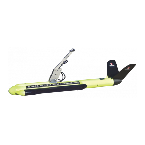
CHAPTER 1 Overview 1.3.2 Subsurface Equipment The subsurface equipment comprises the towfish, as shown in Figure 1-2, and a tow cable. Towfish Figure 1-2: The Towfish consists of a negatively buoyant tow body containing Towfish. port and starboard sonar transducers, processing and control electronics for sonar operation, a downlink demultiplexer for control signals, and an uplink multiplexer for sonar and sensor data. -
Page 21: Functional Description
Functional Description Functional Description This section provides a detailed functional description of the Series 3900 Sonar System operation. 1.4.1 Introduction The Series 3900 Sonar System is a single beam side-looking sonar intended for high resolution survey use. It departs from previous single beam systems in that the swath forming process is implemented digitally using digital signal processing (DSP), rather than analog delay lines, phase shifters, or multipliers and adders. - Page 22 CHAPTER 1 Overview NOTE The transducers are side specific and are not interchangeable. The two transducer arrays are each composed of piezoelectric ceramic sub-arrays that operate as both transmit and receive elements. Each set of sub-arrays is arranged into a continuous line array spanning an overall length of 48 centimeters. The towfish electronics is divided into four individual boards: a 900 kHz Transceiver board, a 445 kHz Transceiver board, a Multiplexer board, and a Power Supply board.
- Page 23 Power supply 900 kHz Transceiver Pressure sensor board board (optional) Multiplexer board Heading, pitch and roll module 445 kHz Transceiver board Figure 1-3: Towfish Electronics Chassis...
- Page 24 CHAPTER 1 Overview Multiplexer board Tow Cable Power Splitter Data and 200 VDC Towfish Power Supply Multiplexed 200VDC Data +5 +15 Multiplexer High Frequency Transceiver Board (900 kHz) Port Transducer Data Starboard Transducer Low Frequency Transceiver Board (445 kHz) Transmit Control TVG Generator Heading, Pitch, Roll Module Pressure Sensor (Optional)
- Page 25 Functional Description The Multiplexer board digitizes the signals from each of Multiplexer board. the transducer sub-array channels along with the signals from the sensors, encodes the data, and transmits a high baud rate digital data stream to the SP-II TPU via the tow cable. The Multiplexer board also receives the trigger signal and command messages which instruct the Transceiver board to fire the arrays and configure aspects of towfish operation.
-
Page 26: Figure 1-5: Sp-Ii Tpu Electronics
Panel Interconnect board Power Integration board 12 VDC power supply board board Figure 1-5: SP-II TPU Electronics... -
Page 27: Figure 1-6: Sp-Ii Tpu Electronics Block Diagram
Figure 1-6: SP-II TPU Electronics Block Diagram... - Page 29 CHAPTER 2: S PECIFICATIONS This chapter includes the physical and performance specifications for the main components of the Series 3900 Sonar System. NOTE Specifications are typical and subject to change without notice. Sonar System Sonar channels: 900 kHz nominal Sonar frequencies: 445 kHz nominal Toneburst, independent pulse controls Transmission pulse:...
-
Page 30: Splashproof-Ii Transceiver And Processing Unit
CHAPTER 2 Specifications Splashproof-II Transceiver and Processing Unit 2.2.1 Physical Characteristics 50.24 cm (19.78 in.) wide Size: 17.1 cm (6.72 in.) high 32.7 cm (12.89 in.) deep 6.8 kg (15.0 lb) Weight: Operating temperature: 0–40° C Designed to IP-66 Ingress protection: 2.2.2 Power Input 250 VA (nominal) -
Page 31: Receiver
Towfish 2.4.4 Receiver High gain, tuned preamplifier with TVG Type: 1 dB nominal Noise figure: 80 dB TVG range: 2.4.5 A/D Converter Pipeline Type: Resolution: 12 bits Linear Quantization: Sample rate: Proprietary 2.4.6 Multiplexer Pulse code modulation (PCM) Modulation format: Time division multiplexing (TDM) Multiplexing format: Number of channels:... -
Page 32: Heading Sensor
CHAPTER 2 Specifications 2.4.9 Heading Sensor ±0.5 RMS Accuracy level: ±1.0 RMS Accuracy tilted: 0.1 Resolution: Repeatability: ±0.1 2.4.10 Pitch and Roll Sensor ±0.2 RMS Accuracy: 0.1 Resolution: ±0.2 Repeatability: 2.4.11 Pressure Sensor (Optional) Selectable Pressure range: ±0.10% Accuracy: Tow Cable Polyurethane jacketed coaxial, Kevlar Type: reinforced... -
Page 33: Chapter 3: Setup And Test
If there is any damage or if any items are missing, immediately contact Klein Marine Systems, Inc. or your KMS sales representative. In addition, record the serial numbers for the towfish, the SP-II TPU and the laptop computer. -
Page 34: Power Requirements
CHAPTER 3 Setup and Test Power Requirements The Series 3900 requires either 88–264 VAC, 47–63 Hz or 12 VDC power to operate. The system is designed to protect against over and under voltage and transient spikes. However, it is always best to check the power source carefully before operating the equipment. -
Page 35: Connecting The Tow Cable
Towfish Setup 3.4.1 Connecting the Tow Cable It is essential to exercise care when making and breaking the tow cable connections at both the SP-II TPU and the towfish ends. WARNING Before connecting the tow cable, verify that the SP-II TPU is turned off and that its AC and DC power cords are disconnected from the power sources. -
Page 36: Connecting The Tow Cable With The Optional K-Wing
CHAPTER 3 Setup and Test 3.4.2 Connecting the Tow Cable with the Optional K-Wing Depressor The shackle on the tow cable connects mechanically to the towfish K-Wing depressor tow bracket using a tow pin. The depressor connects mechanically to the towfish. -
Page 37: Disconnecting The Tow Cable From The Towfish
Connectors must be kept clean and must remain out of the way of traffic while on deck. Klein Marine Systems supplies dummy connectors which can be used to protect the underwater connectors on the towfish and the tow cable when they are connected. -
Page 38: Figure 3-1: Sp-Ii Tpu Front Panel
D/C POLARITY NAV connector indicator T/F TRIG indicator LOCK LOSS DEBUG connector indicator T/F PWR RESP TRIG indicator MAG connector indicator indicator TOWFISH D/C-A/C connector switch RESP TRIG 12 VDC 120/240 VAC connector connector connector connector T/F TRIG EXT TRIG IN 1PPS connector connector... - Page 39 Connecting the System Components BNC connector that is used to input an external EXT TRIG IN: trigger pulse for keying the sonar. BNC connector that is used to input a 1PPS timing 1PPS: pulse. DB9 female connector that connects to a serial port MAG: of the magnetometer control computer.
-
Page 40: Table 3-2: Lan Connector Pinouts
12 VDC Table 3-2: Table 3-3: Connector Pinouts Connector Pinouts FUNCTION FUNCTION Return +12 VDC 120/240 VAC TOWFISH Table 3-4: Table 3-5: Connector Pinouts Connector Pinouts FUNCTION FUNCTION Neutral 200 VDC Power and Telemetry Shield Line Table 3-6: NAV, DEBUG Table 3-7: T/F TRIG, and MAG Connector... -
Page 41: Figure 3-2: Basic System Setup Diagram With Towfish, Navigation And Laptop
Connecting the System Components Sample navigation strings: The preferred is RMC $GPRMC,101842.572,A,3318.577,N,07845.424,W,7.452,2 45.4,050202,0.0,E*72 $GPVTG,245.4,T,245.4,M,7.5,N,13.8,K*76 However the following can also be used $GPGLL,3446.8877,N,07849.0595,W,091739.00,A*1d $GPVTG,290.0,T,290.0,M,06.6,N,12.2,K*4f Navigation System NMEA 0183 4800 baud Formats: GGA&VTG GLL&VTG or Towfish SP-II TPU Ethernet port Laptop computer Figure 3-2: Basic System Setup Diagram with Towfish, Navigation and Laptop Computer Connections... -
Page 42: Figure 3-3: System Setup Diagram With Towfish, Navigation, Acoustic Positioning
3-10 CHAPTER 3 Setup and Test Acoustic Tracking Navigation System Unit NMEA 0183 4800 baud Formats: GGA&VTG GLL&VTG or Depth Acoustic Positioning System Output Format: RMC and TLL or GLL&VTG and TLL or GGA&VTG and TLL Towfish SP-II TPU Ethernet port Laptop computer System Setup Diagram with Towfish, Navigation, Acoustic Positioning System, and... -
Page 43: Operator Controls And Indicators
3-11 Operator Controls and Indicators 2. If connecting a navigation system to the SP-II TPU, connect the supplied navigation cable pigtail to the NAV connector of the SP-II TPU, and then connect the pigtail wires to the navigation system’s RS-232 serial port as follows: •... -
Page 44: System Activation And Test
3-12 CHAPTER 3 Setup and Test Yellow indicator that flashes when the sonar pings. T/F TRIG: Yellow indicator that flashes when a responder RESP TRIG: trigger pulse is output. Red indicator that illuminates when the telemetry LOCK LOSS: link with the towfish is interrupted or lost. D/C POLARITY: Red indicator that illuminates when the polarity of the DC input power is reversed from what it should... -
Page 45: Activating And Testing The System At Sea
3-13 System Activation and Test CAUTION Serious damage to the towfish electronics may occur if the towfish is operated on deck for periods longer than fifteen minutes. Between periods of operation, let the sonar cool for fifteen minutes. In high temperature climates, protect the towfish from direct exposure to the sun prior to and during operation. - Page 46 3-14 CHAPTER 3 Setup and Test 5. Turn on the SP-II TPU by switching the A/C-D/C switch to A/C for AC operation or to D/C for DC operation. The PWR, T/F PWR and LOCK LOSS indicators should illuminate, then after approximately 45 seconds, the LOCK LOSS indicator should turn off and the T/F TRIG indicator should begin flashing at the ping rate of the sonar.
-
Page 47: Chapter 4: Equipment Maintenance
CHAPTER 4: E QUIPMENT AINTENANCE This chapter provides instructions for equipment maintenance and includes guides for taking care of the equipment on a daily, weekly, and long term basis. Maintenance General Comments Equipment used at sea is subjected to severe environmental and handling conditions. -
Page 48: Weekly Maintenance Checklist
CHAPTER 4 Equipment Maintenance 4. Keep the tow cable plugged into the towfish, or use dummy plugs on the tow cable and towfish to keep the connectors from exposure to the salt atmosphere. Remember to put a thin film of silicone grease, such as Dow-Corning 4, on the rubber portion of the underwater connector every time the towfish is disconnected. -
Page 49: Appendix A: Notes On Handling Tow Cables
APPENDIX A: N OTES ON ANDLING ABLES A few methods on how to safely unreel tow cables are provided in this appendix. In addition, how cable kinking can occur is identified along with what can result from this condition. A.1 Unreeling Tow Cable The reel should be revolved and the rope taken off the way it was put on the reel as shown in Figure A-1 for two effective methods. -
Page 50: Uncoiling Tow Cable
APPENDIX A Notes on Handling Tow Cables A.2 Uncoiling Tow Cable Remove ties and roll the coil along the ground so the rope lies straight. There will be no twist or kink in the cable if these instructions are followed. CAUTION If the reel and coil do not revolve freely, it will cause the cable to twist as each turn is taken off. -
Page 51: Effect Of Cable Kinking
Cable Kinking Cable Loop Cable Kink Cable Loop and Kink Figure A-3: A.3.2 Effect of Cable Kinking The effect of kinking is shown in Figure A-4. The cable is permanently damaged Damaged Cable Figure A-4: A.3.3 Result of Cable Kinking The result of cable kinking is that strands and wires are displaced, creating uneven tension which causes excessive wear at the point of the kink. -
Page 53: Appendix B: Configuring And Updating The Sp-Ii Tpu
B.1 Starting Linux TPU Updater Linux TPU Updater is started by double-clicking the Linux TPU Updater icon on the Windows desktop. The Klein Linux TPU Updater dialog box will open as shown Figure B-1. The Klein Linux TPU Updater Dialog Box... -
Page 54: Querying Or Changing The Sp-Ii Tpu Ip Address
7. From the Rate drop-down list box, select the baud rate of the SP-II TPU’s NAV serial port, or select Determine Automatically to have Linux TPU Updater find the rate. The Klein Linux TPU Updater dialog box opens with the current IP address displayed in the text box as shown in Figure B.3. -
Page 55: Editing The Sp-Ii Tpu Startup File
Editing the SP-II TPU Startup File The Klein Linux TPU Updater Dialog Box with Current TPU IP Figure B-3: Address Displayed 8. Enter the new address in the Enter New IP Address text box, and then click Set TPU IP Address A window opens confirming the change: B.3 Editing the SP-II TPU Startup File... -
Page 56: Updating The Sp-Ii Tpu Software
D/C for DC operation. 4. Start Linux TPU Updater. The Klein Linux TPU Updater dialog box opens. 5. Enter the SP-II TPU IP address in the Enter TPU IP Address text box if it is different than the default address, or click if it is the default. - Page 57 Updating the SP-II TPU Software 6. Click Update TPU Software . An dialog box opens that enables file selection. 7. Select and open the update file to download and install. The file is downloaded to the SP-II TPU and installed, and the SP-II TPU software restarts.
-
Page 59: Appendix C: Drawings And Parts Lists
APPENDIX C: D RAWINGS AND ARTS ISTS Listed in Table C-1 are the drawings and parts lists included in this appendix. They are provided for reference and troubleshooting purposes. Each assembly drawing is followed by its corresponding parts list. Table C-1: List of Drawings and Parts Lists DRAWING PARTS... - Page 66 APPENDIX C Drawings and Parts Lists Series 3900 Sonar System Operations and Maintenance Manual P/N 11210085, Rev. 01...
- Page 68 C-10 APPENDIX C Drawings and Parts Lists Series 3900 Sonar System Operations and Maintenance Manual P/N 11210085, Rev. 01...
- Page 72 C-14 APPENDIX C Drawings and Parts Lists Series 3900 Sonar System Operations and Maintenance Manual P/N 11210085, Rev. 01...
- Page 74 C-16 APPENDIX C Drawings and Parts Lists Series 3900 Sonar System Operations and Maintenance Manual P/N 11210085, Rev. 01...
- Page 76 C-18 APPENDIX C Drawings and Parts Lists Series 3900 Sonar System Operations and Maintenance Manual P/N 11210085, Rev. 01...
Need help?
Do you have a question about the 3900 Series and is the answer not in the manual?
Questions and answers