
Related Manuals for Klein 5000 SERIES


Summary of Contents for Klein 5000 SERIES
- Page 1 5000 S ERIES ONAR YSTEM Operations and Maintenance Manual P/N 11210060, Rev. 16 11 Klein Drive Salem, NH 03079-1249 U.S.A. Tel: (603) 893-6131 Fax: (603) 893-8807 www.KleinMarineSystems.com...
- Page 2 This document contains proprietary information, and such information may not be disclosed to others for any purpose or used for any manufacturing purpose without expressed written permission from Klein Marine Systems, Inc. (KMS). The information provided is for informational purposes only and is subject to change without notice.
- Page 3 WARNING Klein Marine Systems recommends all troubleshooting be done by a trained technician. Some circuits in the Sonar Transceiver and Processing Unit have voltages as high as 240 volts, and some circuits in the sonar towfish have 1500 volts. You should familiarize yourself with the location of these voltages before you attempt any troubleshooting.
-
Page 4: Table Of Contents
Table of Contents Table of Contents ..........iv List of Figures . - Page 5 CHAPTER 2: Specifications ....... 2-1 Sonar System ........2-1 Sonar Transceiver and Processing Unit (TPU) .
- Page 6 CHAPTER 3: Preparation for Use ......3-1 Unpacking and Inspection ......3-1 3.1.1 Unpacking the TPU .
- Page 7 CHAPTER 5: Splashproof TPU ......5-1 General Description ........5-1 5.1.1 Venting the Splashproof TPU .
- Page 8 viii Towfish Commands ....... . . C-17 C.6.1 5000 System MUX Commands ..... . C-17 C.6.2 5000 System Transmitter Commands .
- Page 9 Towfish ......... D-39 D.8.1 Testing the Towfish .
-
Page 10: List Of Figures
List of Figures Figure 1-1: TPU—Shown With Access Panel Open ......1-3 Figure 1-2: Towfish . - Page 11 Figure A-4: Cable Length vs. Towfish Depth Graph 4 ......A-6 Figure A-5: Cable Length vs. Towfish Depth Graph 5 ......A-7 Figure B-1: Correct Methods to Unreel Tow Cable .
- Page 12 Figure C-22: The Multiplexer Board ........C-48 Figure C-23: Multiplexer Board Waveforms .
- Page 13 xiii List of Tables Table 1-1: Towfish Connector—at Towfish ........1-7 Table 1-2: TOWFISH Connector Pinouts .
-
Page 14: Sonar System Warranty
Sonar System Warranty What Is Covered LIMITED WARRANTY Subject to the conditions set forth below, equipment sold by Seller is warranted against defects in materials and workmanship, and Seller will repair or exchange any parts proven to be malfunctioning under normal use for one year (12 months) from the date of Delivery as follows: a) SONAR and other associated manufactured products, with the following exceptions:... -
Page 15: Conditions Of Warranty
Conditions Of Warranty a) Seller’s warranty policy does not apply to equipment which has been subjected to accident, abuse, or misuse, shipping damage, alterations, incorrect and/or non- authorized service or equipment on which the serial number plate has been altered, mutilated or removed. b) A suitable proof of purchase, such as, a paid commercial invoice, an installation certificate signed by Seller or an authorized agent must be made available to Seller or Seller’s authorized servicing agent at the time of the Warranty Service. -
Page 16: Changes, Errors And Ommissions
AROSE. Changes, Errors And Ommissions Klein Marine Systems, Inc. reserves the right to make changes to the design or specifications at any time without incurring any obligation to modify previously delivered sonar systems. In addition, while considerable effort has been made to ensure that the information in this manual is accurate and complete, Klein Marine Systems, Inc. -
Page 17: Software License Agreement
Software License Agreement This Software License Agreement is provided by Klein Marine Systems, Inc. © (KMS) for end users of SonarPro software for the KMS Series 3000, UUV-3500, 3900, 4900, 5000, 5000 V2, 5900, HydroChart 3500, HydroChart 5000, and D3500TF Sonar Systems. - Page 18 xviii BATHYMETRIC PROCESSING ATTRIBUTION: Bathymetric processing derived from DGA/GESMA publication in IEEE OCEAN'S 05 Europe Conference Proceedings: "Bathymetric Sidescan Sonar: a System Dedicated to Rapid Environment assessment, ref: 10.1109/OCEANSE.2005.1511695. EXPORT RESTRICTIONS: You agree that you will not export or re-export the Software or accompanying documentation (or any copies thereof) or any products utilizing the Software or such documentation in violation of any applicable laws or regulations of the United States or the country in which you obtained them.
-
Page 19: Preface
ENTIRE AGREEMENT: This License Agreement sets forth the entire understanding and agreement between you and KMS supersedes all prior agreements, whether written or oral, with respect to the Software, and may be amended only in a writing signed by both parties. Preface The Series 5000 Sonar System is a towed multibeam sonar comprising a towed underwater platform and a topside system. -
Page 20: Note, Warning, Caution, And Shock Hazard Notices
SHOCK HAZARD Identifies a potential electrical shock hazard that could cause personal injury or death to yourself or to others. Customer Service KMS technical support can be contacted using any of the following means: Mail Klein Marine Systems, Inc. 11 Klein Drive Salem, NH 03079 Email Klein.Mail@KleinMarineSystems.com... - Page 21 Facsimile (603) 893-8807 For more information about KMS and our products, please go to our Web site at www.KleinMarineSystems.com...
-
Page 23: Chapter 1: Overview
CHAPTER 1: O VERVIEW The Series 5000 Sonar System displays sonar data on a high resolution monitor and will store data on both the hard disk drive and a CD for high capacity storage. Many optional accessories may be added to the basic system for special situations or applications. -
Page 24: Computer Display And Control Unit
CHAPTER 1 Overview 1.1.3 Computer Display and Control Unit The Computer Display and Control Unit (computer) supports the PC based Windows operating system as the display and control interface. This provides for an easy to use familiar graphical user interface and simple expansion capabilities to a wide assortment of equipment. -
Page 25: Subsurface Equipment
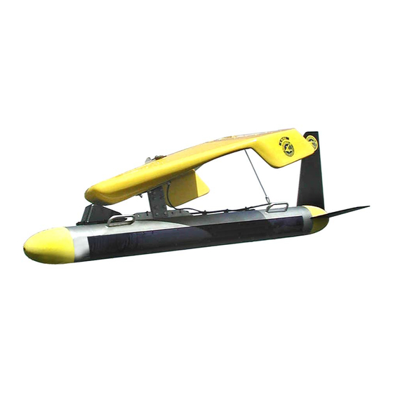
Physical Description Figure 1-1: TPU—Shown With Access Panel Open Computer Display and Control Unit (computer). Most operator functions are accomplished through the use of the computer which supports the PC based Windows operating system as the display and control interface for the sonar signals. -
Page 26: Theory Of Operation
CHAPTER 1 Overview Figure 1-2: Towfish in either a lightweight polyurethane jacketed Kevlar reinforced design or a double armored steel design. The lightweight design is used for operations with cable lengths of 300 meters and under. The double armored design is used for cable lengths longer than 300 meters. -
Page 27: Towfish
Theory of Operation The Series 5000 departs from previous multibeam systems in that the swath forming process is implemented digitally using digital signal processing (DSP), rather than analog delay lines, phase shifters, or multipliers and adders. The primary advantage of this technique is a reduction in the size and weight of the towfish. -
Page 28: Figure 1-3: Towfish Block Diagram
CHAPTER 1 Overview Figure 1-3: Towfish Block Diagram Transmitter board. The Transmitter board produces a transmit pulse, at the start of a swath, that illuminates the sea floor over a defined footprint. The pulse length is nominally 100 µs. The Transmitter board is composed of six individual transmitting channels, each of which is connected to two sub-arrays of both the port and starboard transducer. -
Page 29: Table 1-1: Towfish Connector—At Towfish
Theory of Operation to allow the receive signals to enter a fixed gain low noise preamplifier stage. The output of the preamplifier is input to a voltage controlled amplifier (VCA) which performs the TVG function. The gain versus time relationship, TVG, that is applied identically to all channels is digitally synthesized from a predefined curve stored in a PROM on the Multiplexer board. -
Page 30: Figure 1-4: Towfish Connector-At Towfish
CHAPTER 1 Overview Figure 1-4: Towfish Connector—at Towfish 1.4.3 Transceiver and Processing Unit The TPU provides signal processing along with the system control and data telemetry functions. The TPU is composed of three circuit boards: an embedded CPU board, a Demultiplexer board, and a Digital Signal Processor (DSP) board. The TPU also contains a 200-volt towfish power supply and a TPU power supply. - Page 31 Theory of Operation CPU board. The CPU board is an embedded MVME-5100-based processor board that enables external control of the TPU by a PC connected via an Ethernet 100BaseT local area network (LAN), providing control over system functions. All functions, including communicating the operating parameters to the DSP and extracting sensor data from the Demultiplexer board, are communicated over the LAN.
-
Page 32: Figure
1-10 CHAPTER 1 Overview Front panel. The power switch is located on the access panel as shown in Figure 1-1 on page 1-3. All control of the TPU is done remotely via the LAN. Power supply. The power supply provides 200 VDC to energize the towfish via the tow cable. -
Page 33: Figure 1-8: Com1 And Com2 Connectors
1-11 Theory of Operation Figure 1-7: AC Connector Table 1-3: AC Connector Pinouts PIN NO. LABEL FUNCTION AC line AC neutral Ground Figure 1-8: COM1 and COM2 Connectors... -
Page 34: Figure 1-9: Parallel Connector
1-12 CHAPTER 1 Overview Table 1-4: COM1 and COM2 Connector Pinouts PIN NO. LABEL FUNCTION No connection Data input Data output No connection Ground No connection Figure 1-9: PARALLEL Connector Series 5000 Sonar System Operations and Maintenance Manual P/N 11210060, Rev. 16... - Page 35 1-13 Theory of Operation Table 1-5: PARALLEL Connector Pinouts PIN NO. LABEL FUNCTION TRIGGER “Ping” signal indicating start of swath STROBE Data strobe SEL 3 SEL 2 Data select line (See note below) SEL 1 SEL 0 Ground Data bit 11 Data bit 10 Data bit 9 Data bit 8...
- Page 36 1-14 CHAPTER 1 Overview Table 1-6: System Fuses BLOW FUSE AMP/VOLT SIZE LOCATION CHARACTERISTICS Rear panel, (2) @ 0.25 X Main AC 3 A, 250 V below AC power 1.25 inch connector Rear panel 6.3 A above Towfish 5 X 20 mm TOWFISH Slow-Blow 250 V connector...
-
Page 37: Sonar System
CHAPTER 2: S PECIFICATIONS This chapter includes the physical and performance specifications for the main components of the Series 5000 Sonar System. NOTE Specifications are typical and subject to change without notice. Sonar System Sonar channels: Multiple side scan sonar channels and 6 sensor/auxiliary channels Sonar frequencies: 500 kHz nominal (455 kHz actual) -
Page 38: Sonar Transceiver And Processing Unit (Tpu)
CHAPTER 2 Specifications Sonar Transceiver and Processing Unit (TPU) 2.2.1 TPU Operation Operator interface: Manual operator controls 2.2.2 Input/Output Ports (I/O) Parallel: 2.2.3 Trigger Input The trigger input is used to trigger the system externally. Quantity: Input level: TTL compatible, positive edge triggered Rise time: 1 µs maximum Pulse width:... -
Page 39: Towfish
Computer Display and Control Unit 2.2.6 RS-232 COM 2 Port Quantity: Baud rate: 4800 baud Connector: 9-pin DSUB for receiving navigation data 2.2.7 LAN Input/Output Port Quantity: 2.2.8 Power Input Power consumption: 250 VA (nominal) Input voltage: 115 VAC, 50–60 Hz, 4A; 220 VAC, 50 Hz, 2 A 2.2.9 Physical Characteristics... -
Page 40: Transmitter
CHAPTER 2 Specifications 2.5.3 Transmitter Type: Toneburst Pulse width: 50 µs, 100 µs, 200 µs Driver: Class-D MOSFET 2.5.4 Receiver Type: High gain, tuned preamplifier with TVG Noise figure: 1 dB nominal TVG range: 80 dB 2.5.5 A/D Converter Type: Pipeline Resolution: 12 bits... -
Page 41: Heading Sensor
Tow Cables Size: 203 cm (79.9 in.) long 16.8 cm (6.6 in.) diameter 30.5 cm (24 in.) wide, including tail fins 61.0 cm (24 in.) high, including tail fins Weight in air: 70.5 kg (155 lb) Weight in water: 47.7 kg (105 lb) 2.5.9 Heading Sensor Accuracy level:... -
Page 42: Steel Tow Cable
CHAPTER 2 Specifications 2.6.2 Steel Tow Cable Type: Double layer, counter helical, galvanized improved plow steel (GIPS) Conductors: Coaxial copper Diameter (OD): 10.2 mm (0.40 in.) Breaking strength: 4990 kg (11,000 lb) Working load: 1247 kg (2750 lb) Operational length: 3000 m maximum, depending on cable Voltage rating: 1200 VDC... -
Page 43: Unpacking And Inspection
Remove the computer from the shipping container, and set it on a sturdy, flat surface. Inspect the computer for signs of damage. If there is any damage or if any items are missing, immediately contact Klein Marine Systems, Inc. or your KMS sales representative. Record the serial numbers of the computer modules. -
Page 44: Unpacking The Towfish
The tow cable is shipped on a cable palette or reel. Inspect the cable for damage. If there is any damage or if any items are missing, immediately contact Klein Marine Systems, Inc. or your KMS sales representative. The TPU end of the cable has a Type N connector. -
Page 45: Power Connection
Power Connection Power Connection The Series 5000 requires AC power to operate. The power source requirements are 115 VAC, 50–60 Hz, single phase or 220 VAC, 50 Hz. The system is designed to protect against over and under voltage and transient spikes. However, it is always best to check the power source carefully before operating the equipment. -
Page 46: Power Line Fuse
CHAPTER 3 Preparation for Use Table 3-1: TPU Power Cord Wiring COLOR FUNCTION Yellow/green Ground (earth) Blue Neutral Brown After checking the power source, and modifying the power cord if required, connect the TPU to AC power. 3.3.2 Power Line Fuse The main AC power input line is protected by two 3-A, 0.25 x 1.25-inch fast acting fuses rated for 250 volts. -
Page 47: Grounding
Towfish Setup 3.3.4 Grounding It is important that the TPU be well grounded to minimize potential hazards to the operator and electrical interference from other equipment. A good ground for the system is a low impedance, well conducted path to the sea water. Always check the quality of the electrical ground. -
Page 48: Figure 3-1: Towfish Connection
CHAPTER 3 Preparation for Use 3.4.2 Tow Cable Electrical Connection It is essential to exercise care when making and breaking the tow cable connections at both the TPU and the towfish ends. The electrical connection procedures are provided below. WARNING In all of the procedures which follow, be sure that the power is turned off. -
Page 49: Towfish And Optional Depressor Connection
Towfish Setup The tow cable jumper is secured with cable ties to the top of the towfish. The towfish mechanical and electrical connection procedure is as follows: Remove the retaining ring from the beveled end of the tow pin and withdraw the pin from the tow bracket. -
Page 50: Tow Cable Disconnection
Connectors must be kept clean and must remain out of the way of traffic while on deck. Klein Marine Systems supplies dummy connectors which can be used to protect the underwater connectors on the towfish and cable when they are not mated to each other. -
Page 51: Quick Start Installation And Operating Guide
Quick Start Installation and Operating Guide WARNING Power to the sonar system must be turned off prior to connection or disconnection of the tow cable to either the towfish or the TPU, as serious damage may occur to the sonar system electronics or injury may occur to the operator as a result of this action. -
Page 52: Deck Test
It should contain GLL&VTG, GGA&VTG or RMC at 4800 baud. If 4800 baud is not available, contact Klein Marine Systems, Inc. technical support for assistance. 10. Run the LAN cables from the TPU to the Ethernet Hub and from the Ethernet Hub to the computer. -
Page 53: At-Sea Test
3-11 Quick Start Installation and Operating Guide 5. On the computer, start SonarPro and observe that the towfish is transmitting by viewing the output pulse in the Scan window. Also check that GPS data are being displayed in the Information window in SonarPro. 6. -
Page 55: Maintenance General Comments
CHAPTER 4: E QUIPMENT AINTENANCE This chapter provides instructions for equipment maintenance and includes guides for taking care of the equipment on a daily, weekly, and long term basis. In addition, instructions are provided for replacing the fixed tail cone assembly. Maintenance General Comments Equipment used at sea is subjected to severe environmental and handling conditions. -
Page 56: Weekly Maintenance Checklist
CHAPTER 4 Equipment Maintenance 4. Keep the tow cable plugged into the towfish, or use dummy plugs on the tow cable and towfish to keep the connectors from exposure to the salt atmosphere. Remember to put a thin film of silicone grease, such as Dow-Corning 4, on the rubber portion of the underwater connector every time the towfish is disconnected. -
Page 57: Figure 4-1: Towfish Tail With Rear Center Pin In Place
Replacing the Fixed Tail Cone Assembly Replacing the Fixed Tail Cone Assembly The following procedure describes how to install or replace the fixed tail cone assembly, P/N 14102954, used on the towfish. This assembly is installed on all new Series 5000 towfish and can be retrofitted on older Series 5000 towfish using the collision tolerant tail cone assembly. -
Page 58: Tail Cone Being Aligned And Attached To Towfish
CHAPTER 4 Equipment Maintenance With the large hole to the upper right, align the tail cone with the rear center pin and thread the rear tail cone bolt (7) into the rear center pin using the 8-mm hex key. Figure 4-2: Tail Cone being Aligned and Attached to Towfish 3. -
Page 59: Figure 4-4: Crossbar Used To Secure Tail Cone Parts
Replacing the Fixed Tail Cone Assembly 4. Install the crossbar (4) into the large hole. Figure 4-4: Crossbar Used to Secure Tail Cone Parts 5. Using the flat bladed screw driver, align the threaded hole in the crossbar (4) and screw the bolt (7) with the retaining cup (5) into the crossbar with the 8-mm hex... -
Page 60: Tail Fins Being Inserted Into Tail Cone
CHAPTER 4 Equipment Maintenance 6. Install the two horizontal tail fins (2) and the vertical tail fin (3) by inserting the forward slot into the towfish body. The rearward slot should be secured by the retaining cup. Figure 4-6: Tail Fins being Inserted into Tail Cone 7. -
Page 61: Figure 5-1: Splashproof Tpu
CHAPTER 5: S PLASHPROOF Ror use in open boat operations where exposure to rain and spray is likely, a lightweight, rugged, splashproof configuration of the Transceiver and Processor Unit (TPU) is available. The Splashproof TPU is similar to the rack mount configuration but is housed in a watertight, corrosion proof, high impact resistant Pelican Protector Case. -
Page 62: Figure 5-2: Splashproof Tpu Vent Closed
CHAPTER 5 Splashproof TPU 5.1.1 Venting the Splashproof The Splashproof TPU includes a vent which can be easily opened or closed. The TPU is shipped with the vent closed as shown in Figure 5-2. CAUTION The vent on the TPU must be opened when the outside air temperature exceeds °... -
Page 63: Splashproof Tpu Connector Panel
General Description View ports Connector panel Figure 5-4: Splashproof TPU Connector Panel The external connections are the following TOWFISH: 8-pin bulkhead connector that connects to the towfish using the towfish cable. This connector is internally wired to a BNC connector that connects to the 200 VDC power supply. -
Page 64: Operator Controls And Indicators
CHAPTER 5 Splashproof TPU MAG OUT: 6-pin bulkhead connector that connects to a magnetometer. (Not used.) DEBUG: 3-pin bulkhead connector that connects to the serial port of a computer and can be used to view and save the boot sequence data using HyperTerminal. This connector is internally wired to an RJ-45 connector that connects to the DBUG connector of the CPU board. -
Page 65: Figure 5-5: Front Panel Of Vme Chassis Inside Splashproof Tpu
TRIG 1 OUT VME chassis COM2 COM1 CABLE DSP board Demultiplexer board CPU board Low voltage power supply DEBUG VOLTAGE SELECT switch (See CAUTIONS on page 5-9.) Figure 5-5: Front Panel of VME Chassis inside Splashproof TPU... -
Page 66: Vme Backplane And Power Supply Connections Inside Splashproof Tpu
VME backplane VME fan VME chassis Low voltage power supply 12 VDC power supply Transformer Towfish fuse GPS fuse Power fuse Choke 200 VDC power supply Figure 5-6: VME Backplane and Power Supply Connections inside Splashproof TPU... -
Page 67: Functional Components
General Description VOLTAGE SELECT: Slide switch which selects 115 or 230 VAC operation. This switch is located inside the TPU and is shown in Figure 5-5. (See CAUTIONS on page 5-9 regarding the use of this switch.) The switch positions are 115V and 230V for 115 VAC and 230 VAC operation. - Page 68 CHAPTER 5 Splashproof TPU 200 VDC power supply. The 200 VDC power supply inputs 200 VAC from the transformer and provides 200 VDC to power the towfish. In addition, this power supply provides data coupling to and from the towfish on the 200 VDC power.
-
Page 69: Setting Up And Connecting The Splashproof Tpu
Setting up and Connecting the Splashproof TPU Setting up and Connecting the Splashproof TPU Setting up and connecting the Splashproof TPU is similar to that of the rack mount TPU as described in APPENDIX D: “General Setup, Configuration and Troubleshooting.” However, the power connections are different. In addition, because the LAN connector is internally wired through a crossover block to the LAN connector of the CPU board, a crossover cable (not supplied) is required instead of the supplied waterproof LAN cable when connecting the TPU to a local... -
Page 70: Activating The Splashproof Tpu
5-10 CHAPTER 5 Splashproof TPU To connect power to the TPU: If you will be connecting a 115 VAC or 12 VDC power source to the TPU, set the VOLTAGE SELECT switch inside the TPU to 115V. Refer to the CAUTIONS stated above. -
Page 71: Specifications
5-11 Specifications 5. Wait for the network connection to establish communications with the computer. 6. Switch the RUN/STAND BY switch to RUN. 7. The boot sequence will begin, and when completed, the CARRIER LOSS and LOCK LOSS indicators on the Demultiplexer board will turn off. These indicators can be viewed through the view ports on the connector panel of the TPU. - Page 72 5-12 CHAPTER 5 Splashproof TPU Table 5-1: List of Drawings DRAWING TITLE Assembly Drawing, Connector Panel, SP 3000/5000, TPU (Sheets 1 and 2) 15104342 Wiring Diagram, SP 3000/5000 Base Unit 14314343 14314344-03 Wiring Diagram, Splashproof System 5000 15104403 Assembly Drawing, Connector, accessory Kit, SP TPU Series 5000 Sonar System Operations and Maintenance Manual P/N 11210060, Rev.
- Page 79 APPENDIX A: S AMPLE OWING HARACTERISTICS Five towing characteristic graphs are included in this appendix as Figure A-1 through Figure A-5. Two of the graphs were generated without any additional weight being added to the towfish, and the other two graphs were made with our K-Wing II Depressor attached to the towfish.
- Page 80 More details on towing characteristics, such as tension, layback, etc., are available at Klein Marine Systems, Inc . We would be glad to help you meet your requirements. Your experiences in towing our side scan sonar under various conditions would be helpful in upgrading our data, and we respectfully solicit your comments.
-
Page 81: Figure A-1: Cable Length Vs. Towfish Depth Graph 1
Figure A-1: Cable Length vs. Towfish Depth Graph 1... -
Page 82: Figure A-2: Cable Length Vs. Towfish Depth Graph 2
Figure A-2: Cable Length vs. Towfish Depth Graph 2... -
Page 83: Figure A-3: Cable Length Vs. Towfish Depth Graph 3
Figure A-3: Cable Length vs. Towfish Depth Graph 3... -
Page 84: Figure A-4: Cable Length Vs. Towfish Depth Graph 4
Figure A-4: Cable Length vs. Towfish Depth Graph 4... -
Page 85: Figure A-5: Cable Length Vs. Towfish Depth Graph 5
Figure A-5: Cable Length vs. Towfish Depth Graph 5... -
Page 87: B.1 Unreeling Tow Cable
APPENDIX B: N OTES ON ANDLING ABLES A few methods on how to safely unreel tow cables are provided in this appendix. In addition, how cable kinking can occur is identified along with what can result from this condition. B.1 Unreeling Tow Cable The reel should be revolved and the rope taken off the way it was put on the reel as shown in Figure B-1 for two effective methods. -
Page 88: B.2 Uncoiling Tow Cable
APPENDIX B Notes on Handling Tow Cables B.2 Uncoiling Tow Cable Remove ties and roll the coil along the ground so the rope lies straight. There will be no twist or kink in the cable if these instructions are followed. CAUTION If the reel and coil do not revolve freely, it will cause the cable to twist as each turn is taken off. -
Page 89: B.3.2 Effect Of Cable Kinking
Cable Kinking Cable Loop Cable Kink Figure B-3: Cable Loop and Kink B.3.2 Effect of Cable Kinking The effect of kinking is shown in Figure B-4. The cable is permanently damaged Figure B-4: Damaged Cable B.3.3 Result of Cable Kinking The result of cable kinking is that strands and wires are displaced, creating uneven tension which causes excessive wear at the point of the kink. - Page 91 APPENDIX C: TPU S OFTWARE NTERFACE ONTROL This appendix describes the various control and initialization procedures for the 3000, 5000 and 5900 Sonar System TPUs. The information in this document applies to TPU software version 5.3 and later. C.1 Control Methods Aside from control of the TPU via the Ethernet interface, the 3000/5000/5900 System may be controlled via NMEA messages or via a startup script file.
- Page 92 APPENDIX C TPU Software Interface and Control RESPDIV {d = 0 - 15}. Sets the responder divisor to 2^d, where d = 0 – 15. A value of 15 turns the responder off. Default is 15 (off). RESPFREQ {d = 0 - 15}. Sets the responder frequency to 24 kHz + d * 500 Hz, where d = 0 –...
- Page 93 Startup Script TRIGOUTTYPE {d = 0,1}. Sets the Trig 1 Out trigger type. For normal installations the type is ‘0’ and a pulse is generated simultaneous with the towfish trigger. For the BlueFin AUV project the type should be set to ‘1’ which programs the port to output a pulse 31 milliseconds prior to the end of the range and at a rate such that the rate is maximum without exceeding 4 Hz.
- Page 94 DO NOT set this unless there is a fiber hooked up to the towfish and the fiber is properly terminated into the Klein FOI-01 Fiber Optic interface module. Setting this to ‘0’ deactivates the laser and activates the standard coaxial uplink.
- Page 95 Startup Script LBOGAIN {d = 0 – 3}. Along with the PREEMPHAIS variable (see above) this allows longer cables to be driven. The default value of ‘1’ provides for optimum performance on short to medium length cables. A value of ‘0’ decreases the uplink signal level by 6 dB.
- Page 96 APPENDIX C TPU Software Interface and Control towfish-motion-induced imbalance as well. A value between 50 and 200 is recommended. The default value of ‘0’ deactivates the new algorithm and uses the previous algorithm. MAXSAMPLES {d = 4096 – 65536} (System 5900 only). This limits the maximum number of samples generated per ping per beam.
- Page 97 Startup Script BLOVERRIDE {d = 0,1} (System 5000 only). Setting d = '1' limits the number of beams to 4. Setting d = '0' uses 5 beams. Note: If Bathy is enabled, number of beams is also limited to 4. Default is '0'. DECIMATIONMODE (System 5900 only).
- Page 98 APPENDIX C TPU Software Interface and Control SYS7KCONFIG33_64 {d = 0 - 0xFFFFFFF} (System 7XXX/5900 Only). Sets the channel configuration mask for channels 33 thru 64 to 'd'. Each bit in the mask enables a channel. For example 0x10000001 would enable channels 33 and 61 and disable all other channels.
- Page 99 Startup Script SUBBOTTOM {d = 0,1} (System 3000 Only). Setting d = '1' indicates the Towfish has the sub bottom profiler option. Enabling this option will cause the TPU to allow the sub bottom profiler to be enabled and sub bottom data collected.
- Page 100 "startup script" parameter field in the boot configuration. (See “TPU LAN Configuration Setup” on page D-24 for details on boot parameters.) For example: if the file is located in /klein, then the "startup script" parameter must be set to / klein/startup.ini.
- Page 101 C-11 Remote Control SonarPro connected as master) then many of the commands will have no effect as there can only be one master and the software request to change a parameter will be rejected because there is an existing master. Many commands will echo the current setting if the data field is replaced with "?".
- Page 102 C-12 APPENDIX C TPU Software Interface and Control Format the hard-drive. WARNING: this will erase all data. Only use if a new disk has been installed. Note: only supported if local disk-drive option installed. FLdddd: Set the length of the recorded files where d is the number of pings per file.
- Page 103 C-13 Remote Control SC<data>: Synchronize the internal clock. The <data> field is defined as follows: mm,dd,yyyy,hh,mm,ss,mmm which is month, day, year (4 digit), hours, minutes, seconds, and milliseconds. Prepare the system for shutdown. This puts the system in standby, stops any recording, and closes all files. When shutdown preparations are complete a status message is issued and the SD value is set to one.
-
Page 104: C.4 Snapshots
C-14 APPENDIX C TPU Software Interface and Control VFd: Turn velocity filter on|off, where d = 0 is off and d = 1 is on. Default is on. WFd: Set transmit waveform, where d = 0 is 50 µs, d = 1 is 100 µs and d = 2 is 200 µs. -
Page 105: C.5 Messages
C-15 Messages C.5 Messages C.5.1 Status Message Upon query of the system by the ST (status) command the system outputs a status message of the form: $PKLA,ST,RSdWFdRMdSMdDMdTPdVFdRCdSDdHDddERdd*hh<CR><LF> where the fields are as described above and HD is the percentage of hard drive space used and ER is an error/health monitoring byte (in ASCII hex representation) where zero indicates normal operation and a non-zero value indicates an error state defined as:... -
Page 106: C.5.2 Heartbeat Message
C-16 APPENDIX C TPU Software Interface and Control TPU watchdog. If this bit is set then a task may be locked. The TPU uses multi-threaded OS technology where multiple tasks are performed simultaneously. These tasks include acquiring the data, formatting it, parsing the sensor messages, handling navigation input, etc. -
Page 107: C.6 Towfish Commands
C-17 Towfish Commands NOTE The systems are available with a range of pressure sensors. This is the reason that absolute depth is not calculated by the TPU. C.6 Towfish Commands Although sonar control is normally performed using the Ethernet or NMEA interfaces, direct control of the towfish is possible. -
Page 108: C.6.2 5000 System Transmitter Commands
C-18 APPENDIX C TPU Software Interface and Control $MLd: Sets the uplink pre-emphasis amount where d = 0 – 7. See the ‘PREEMPHASIS’ description in the startup script above for more information. This command can be used to fine tune the uplink for various cables. When the performance is optimized then this value can be incorporated into the startup script to initialize the pre- emphasis on boot-up. -
Page 109: C.6.3 System 5000 Actuator Commands
C-19 Towfish Commands C.6.3 System 5000 Actuator Commands For System 5000s equipped with an actuated wing, the wing actuator may be controlled using towfish commands. This is not recommended. The syntax is $MA<command><CR><LF> where <command> is a actuator control command. Refer to the appropriate actuator motor controller user's manual for more information on actuator commands. -
Page 110: C.6.6 System 5900 Mux Commands
C-20 APPENDIX C TPU Software Interface and Control Likewise for the 3000 System commands may be sent to an auxiliary sensor connected to the towfish auxiliary RS-232 port. The format of the commands is obviously specific to the sensor used. To issue a command to an auxiliary sensor the format would be $A<command><CR><LF>. -
Page 111: C.6.7 System 5900 Dsp Commands
C-21 Towfish Commands C.6.7 System 5900 DSP Commands The following commands are available to control the System 5900 DSP board: $DR: Resets the DSP. This command resets the DSP card to its initial default state. $DTd: Selects the DSP test mode where d = 0 – 5. Test mode ‘0’ is off. -
Page 112: C.6.9 System X000 Sub-Bottom Profiler (Sbp) Commands
C-22 APPENDIX C TPU Software Interface and Control $XMdddd: Selects the transmitter mask. Each transmitter board is comprised of 16 transmitters. Each transmitter can be individually masked. Each bit in the hex value dddd corresponds to a transmitter. For example $XM0001 would enable only the first transmitter. -
Page 113: C.6.10 Datalogger On/Off Commands
C-23 Towfish Commands C.6.10 Datalogger On/Off commands The 4 acceptable commands will be: $PKLA,PC1: Will turn power off to the sonar only. $PKLA,PC2: Will turn power off to the TPU only. $PKLA,PC3: Will turn power on to both the TPU and sonar. $PKLA,PC0: Will turn power off to both the TPU and sonar. -
Page 115: Troubleshooting
WARNING Klein Marine Systems, Inc. recommends all troubleshooting be done by a trained technician. Some circuits in the Sonar Transceiver and Processing Unit have voltages as high as 240 volts, and some circuits in the sonar towfish have 1500 volts. -
Page 116: D.1 Basic System Requirements
APPENDIX D General Setup, Configuration and Troubleshooting D.1 Basic System Requirements Although we suggest that you get the fastest available computer at the time of purchase, it is recommended that you use the following minimum PC system. • 400 MHz Pentium II •... - Page 117 Basic System Setup Sample navigation strings: The preferred is RMC $GPRMC,101842.572,A,3318.577,N,07845.424,W,7.452,2 45.4,050202,0.0,E*72 $GPVTG,245.4,T,245.4,M,7.5,N,13.8,K*76 However the following can be used also $GPGLL,3446.8877,N,07849.0595,W,091739.00,A*1d $GPVTG,290.0,T,290.0,M,06.6,N,12.2,K*4f Navigation Unit 4800 baud Format: RMC or GLL&VTG or GGA&VTG Slip Ring Computer Terminal or PC boot device processor number Running HyperTerminal for host name...
- Page 118 APPENDIX D General Setup, Configuration and Troubleshooting Navigation Unit Acoustic Tacking Unit NMEA 0183 4800 Baud Formats: RMC, or GLL&VTG or GGA&VTG Depth from PC Com 2 Navigation Com puter System Output Format: RMC and TLL or GLL&VTG and TLL or Slip Ring GGA&VTG and TLL Trig Div 2 Out...
-
Page 119: D.3 Installing Sonarpro
Multiple versions of SonarPro can reside on the same computer. When installation is complete, verify that your startup.ini file or your vxWorks files are located directly in the klein directory. D.4 Configuring the LAN Connection Three LAN configuration setup procedures are provided, one for each of three Windows operating systems: NT, 2000 and XP. - Page 120 APPENDIX D General Setup, Configuration and Troubleshooting 3. Note your computer name. 4. Select the Protocols tab. Series 5000 Sonar System Operations and Maintenance Manual P/N 11210060, Rev. 16...
- Page 121 Configuring the LAN Connection 5. Select TCP/IP Protocol, click Properties , and then verify or set your IP address and subnet mask. These settings will be used later to direct the TPU to the location of the boot program vxWorks. Next, see if you have Internet Service Manager and FTP Service installed and set up on your computer: 1.
- Page 122 APPENDIX D General Setup, Configuration and Troubleshooting NOTE A new empty directory C:\InetPub\ftroot will be created on your C: drive. Do not delete it. 2. On the desktop choose Start/ Programs/Microsoft Peer Web Services (Common)/Internet Service Manager. 3. Right-click the computer running the FTP service and choose Service Properties.
- Page 123 Configuring the LAN Connection 5. Click the Directories tab and check for the c:\klein directory. If it is not present click and set up the dialog box as shown. Make sure the dialog boxes match.
- Page 124 D-10 APPENDIX D General Setup, Configuration and Troubleshooting Finally, set up the user profile: 1. On the desktop choose Start/ Programs/ Administrative Tools/(Common)/ User Manager. Series 5000 Sonar System Operations and Maintenance Manual P/N 11210060, Rev. 16...
-
Page 125: D.4.2 Windows 2000 Lan Configuration Setup
D-11 Configuring the LAN Connection 2. Check or add new user klein. If adding a new user, choose User/New User, enter klein in all the text boxes and set up the check boxes as shown. If checking the user klein setup, click klein and check the dialog box. - Page 126 D-12 APPENDIX D General Setup, Configuration and Troubleshooting 2. Right-click Network and Dial-up Connection. 3. Right-click Local Area Connection. The Local Area Connection Properties dialog box opens. 4. Select Internet Protocol (TCP/IP), and then click Properties 5. Enter the IP address and the subnet mask for your computer, and then click Series 5000 Sonar System Operations and Maintenance Manual...
- Page 127 D-13 Configuring the LAN Connection Next, set up the FTP service: 1. On the desktop choose Start/Settings/Control Panel/Administrative Tools/ Computer Management. NOTE If the Internet Information Services item is not in the Computer Management (Local) menu above, it will need to be installed. Locate your Windows CD, select Install Add-on Components, and then select Internet Information Services.
- Page 128 D-14 APPENDIX D General Setup, Configuration and Troubleshooting 2. Select Internet Information Services. 3. Right-click Default FTP Site and choose Properties. The Default FTP Site Properties dialog box will open to the FTP Site tab. 4. Enter the parameters as shown.
- Page 129 D-15 Configuring the LAN Connection 5. Click the Home Directory tab. 6. Set up the dialog box as shown, including entering C:\ in the Local Path text box. Finally, set up the user profile: 1. On the desktop choose Start/Settings/ Control Panel/Administrative Tools/ Computer Management.
-
Page 130: D.4.3 Windows Xp Lan Configuration Setup
3. Right-click Users, and then choose New User. The New User dialog box will open. 4. Enter klein in all the text boxes and set up the check boxes as shown. 5. Click Create . 6. Verify that your vxWorks file is located in the klein directory. - Page 131 D-17 Configuring the LAN Connection 2. Right-click Network Connections. The Network Connection dialog box opens. 3. Right-click Local Area Connection. The Local Area Connection dialog box opens. 4. Select Internet Protocol (TCP/IP), and then click Properties...
- Page 132 D-18 APPENDIX D General Setup, Configuration and Troubleshooting 5. Enter the IP address and the subnet mask for your computer, and then click Next, set up the FTP service: 1. On the desktop choose Start/Control Panel/Administrative Tools/Computer Management. Series 5000 Sonar System Operations and Maintenance Manual P/N 11210060, Rev.
- Page 133 D-19 Configuring the LAN Connection NOTE If the Internet Information Services item is not in the Computer Management (Local) menu above, it will need to be installed. Locate your Windows XP Professional CD, select Install Optional Windows Components, and then select Internet Information Service (IIS) and add it to the list of other checked components.
- Page 134 D-20 APPENDIX D General Setup, Configuration and Troubleshooting 5. Click the Home Directory tab. 6. Set up the dialog box as shown, including entering C:\ in Local Path text box. Finally, set up the user profile. 1. On the desktop choose Start/Control Panel/Administrative Tools/Computer Management.
- Page 135 3. Right-click Users, and then choose New User. The New User dialog box opens. 4. Enter klein in all the text boxes and set up the check boxes as shown. With the addition of XP Service Pack 2, Microsoft has added a firewall. This firewall prevents the system from downloading the vxWorks program and will cause the system to not boot up properly and usually produce an error message.
- Page 136 D-22 APPENDIX D General Setup, Configuration and Troubleshooting 2. Right-click Network Connections. The Network Connection dialog box opens. 3. Right-click Local Area Connection., and then choose Properties. The Local Area Connection dialog box opens. 4. Select Internet Protocol (TCP/IP), and then click Properties Series 5000 Sonar System Operations and Maintenance Manual P/N 11210060, Rev.
- Page 137 D-23 Configuring the LAN Connection 5. Select the Advanced tab. 6. Click Settings , select the option, and then click Verify that your vxWorks file is located in the klein directory.
-
Page 138: D.5 Tpu Lan Configuration Setup
: fei unit number processor number host name : sonarclient file name : \klein\vxWorks inet on ethernet (e) : 192.168.0.81 host inet (h) : 192.168.0.82 Series 5000 Sonar System Operations and Maintenance Manual P/N 11210060, Rev. 16... - Page 139 | | # # | | | | ##### ##### ####### # # | | 5555555555 000000000 000000000 00000000 555555555 | | 5 | | 555555555 000000000 000000000 000000000 ------------------------------------------------- Copyright (C) 2002 Klein Associates, Incorporated | |____________________________________________________________| | +----------------------------------------------------------------+...
- Page 140 IRIG-B Decoder Board not detected, IRIG support not available. $TA1 $TA1 $TA1 $MT7 $MT7 $MT7 $TW0 $TW0 $TW0 $TDF $TDF $TDF $TR7 $TR7 $TR7 Opening script file on sonarclient:\klein\startup.ini. Processing startup script: $TW0 $TW0 $TW0 $PS1 $PS1 $MT7 $MT7 $MT7 $MT7 $MT7 $MT7 $TW0 $TW0 $TW0...
- Page 141 Turn the TPU off and then back on or press the RST button on the CPU inside the TPU and watch the boot sequence again. The Klein startup.ini file is used to set boot parameters. The following is a typical .ini file.
- Page 142 D-28 APPENDIX D General Setup, Configuration and Troubleshooting set RANGE 2 set TXWAVEFORM 0 set RESPDIV 15 set RESPFREQ 7 set DVLDELAYDELTA 31 set HEARTBEAT 0 set PINGSPERFILE 5000 set SPEEDSOUND 150000 set BEAMBALANCE 100 set PREEMPHASIS 2 set LBOGAIN 1 set DIAGLEVEL 0 SonarPro needs to know the IP address of the TPU.
-
Page 143: D.6 Different Cable Lengths And The Startup.ini File
D-29 Different Cable Lengths and the Startup.ini File D.6 Different Cable Lengths and the Startup.ini File The Series 5000 Sonar Systems operate at high data rates. For optimum performance, settings have been provided to tune the system’s uplink for various cable lengths up to -24 dB of insertion loss. -
Page 144: D.6.1 Tow Cable Considerations
D-30 APPENDIX D General Setup, Configuration and Troubleshooting D.6.1 Tow Cable Considerations For lightweight tow cables, we recommend that you use tow cables with the following characteristics: Type: Polyurethane jacketed, coaxial Kevlar reinforced Conductors: Coaxial copper Diameter (OD): 1.03 cm (0.405 in.) Breaking strength: 2270 kg (5000 lb) Working load:... -
Page 145: Generator, Terminator And Oscilloscope
D-31 Different Cable Lengths and the Startup.ini File D.6.2 Measuring Cable Insertion Loss To get an accurate assessment of your tow cable assembly, we suggest that you use a Hewlett Packard 4194A Impedance/Gain-Phase Analyzer or similar. A sample plot is shown in Figure D-3. Figure D-3: Sample Plot of Tow Cable Characteristics If you do not have access to a Hewlett Packard 4194A Impedance/Gain-Phase... -
Page 146: D.7 Transceiver And Processing Unit
D-32 APPENDIX D General Setup, Configuration and Troubleshooting With the function generator and the oscilloscope connected to the cable, monitor input on the oscilloscope and input a 1 volt peak (2 volt peak-to-peak) sine wave of the specific frequency of interest. Measure the peak output at the other end of the cable on the scope through the 50-ohm termination. -
Page 147: D.7.1 Input Power
D-33 Transceiver and Processing Unit The rear panel of the TPU is shown in Figure D-6. The AC connector, the voltage switch and the fuse are shown in Figure D-7. These items are on the rear panel. Figure D-6: TPU Rear Panel Figure D-7: AC Connector, Voltage Switch and Fuse on the Rear Panel of the TPU... -
Page 148: D.7.2 Towfish Fuse
D-34 APPENDIX D General Setup, Configuration and Troubleshooting D.7.2 Towfish Fuse The towfish fuse is on the 200 VDC line to the towfish. Access to this fuse is located on the back of the TPU just above the towfish connector. The towfish fuse is a 6.3-A, 250-volt slow blow (P/N 13000163). -
Page 149: D.7.5 Power Supplies
D-35 Transceiver and Processing Unit D.7.5 Power Supplies Refer to Drawing 14303210. A 200 VDC power supply supplies power to the towfish and is fused on the back of the TPU. 200 VAC enters the power supply board from the transformer at JP2, and 200 VDC is generated which and can be measured between the base of the fuse holder and the top of the BNC cable at the TOWFISH connector J1 on the rear panel of the TPU as shown in Figure D-9. -
Page 150: D.7.6 Tpu Power Up And Test Sequence
D-36 APPENDIX D General Setup, Configuration and Troubleshooting Figure D-10: Location of D9 D.7.6 TPU Power up and Test Sequence SHOCK HAZARD Do not connect or disconnect the tow cable from the towfish or the TPU when power is on. Failure to follow this practice may result in personal injury and will damage the towfish or the TPU electronics, or both. - Page 151 D-37 Transceiver and Processing Unit To power up the TPU and verify proper operation of the TPU and LAN: 1. With the towfish and LAN cables removed from the TPU, turn the power on. This will test the basic TPU. On the DSP board, •...
- Page 152 D-38 APPENDIX D General Setup, Configuration and Troubleshooting 3. Connect the LAN cable through the hub to the computer. You will see the computer port on the hub lit. 4. Turn the TPU on. The TPU port on the hub will light. This will add the LAN side to the TPU test.
-
Page 153: D.8 Towfish
D-39 Towfish On the CPU board, • CPU, BFL, SCSI BUSY, PIB BUSY will all light. • SCSI BUSY, PIB BUSY will go out. • CPU light will blink off and then come back on. • CPU, BFL will both go off and then the CPU will then come back on and stay on for about 12 seconds and then go off, then come back on again. -
Page 154: D.8.1 Testing The Towfish
D-40 APPENDIX D General Setup, Configuration and Troubleshooting Figure D-12: Towfish with Bathymetry Transducer Configuration D.8.1 Testing the Towfish The towfish block diagram is shown in Figure D-13. Figure D-13: Towfish Block Diagram D.8.2 Checking the Telemetry Link to the Towfish Turn the TPU on and check the LOCK LOSS and ERROR lights. -
Page 155: D.8.3 Checking The Transmitters Before Deployment
D-41 Towfish D.8.3 Checking the Transmitters before Deployment Refer to the troubleshooting charts in Table D-1 on page D-42 and Table D-6 on page D-58. These charts allow you to trace signals from the transducer crystals throughout the towfish electronics. The connectors labelled 1P and 2P are on the the port transducer and they connect to the top and bottom, respectively, of the port Receiver board. -
Page 156: Trouble Shooting Chart
D-42 APPENDIX D General Setup, Configuration and Troubleshooting Figure D-15: Image in Sonar Viewer Window During a Rub Test D.8.5 Standard Transducer Configuration Trouble Shooting Chart A troubleshooting chart for the towfish with the standard transducer configuration is shown in Table D-1. Refer to “Checking the Transmitters before Deployment” on page D-41 for information about the troubleshooting chart. -
Page 157: D.8.6 Towfish Bottle Electronics
D-43 Towfish Table D-2: Troubleshooting Chart—2P or 2S Connections TRANSDUCER 10-PIN RECEIVER TRANSMITTER 2P/2S TEST CODE CRYSTAL BULKHEAD BOARD BOARD — Xtal 7 Channel 7 Xtal 8 Channel 8 Xtal 9 Channel 9 Xtal 10 IN10 Channel 10 Xtal 11 IN11 Channel 11 Xtal 12... - Page 158 D-44 APPENDIX D General Setup, Configuration and Troubleshooting assembly screws into the end cap and extracts the electronics. When flipped over, the assembly pushes the electronics end cap into the pressure housing. 2. Position the post with the unthreaded hole to the top. 3.
- Page 159 D-45 Towfish With the towfish electronics out of the pressure housing you can identify some of the components as shown in Figure D-19. Figure D-19: Towfish Electronics...
-
Page 160: D.8.8 Towfish Telemetry
D-46 APPENDIX D General Setup, Configuration and Troubleshooting D.8.8 Towfish Telemetry A block diagram of the towfish telemetry is shown in Figure D-20. Figure D-20: The Towfish Telemetry Details D.8.9 Setting up for Testing the Electronics Remove the towfish electronics as described in “Removing the Towfish Electronics”... -
Page 161: D.8.10 Checking The Multiplexer Board
D-47 Towfish Figure D-21: Towfish Electronics Ready for Servicing D.8.10 Checking the Multiplexer Board The Multiplexer board is shown Figure D-22 and performs the following functions: • Receives the 200 VDC and telemetry from the surface and separates out the telemetry from the 200 VDC. •... -
Page 162: D.8.11 Checking The Transmitter Board
D-48 APPENDIX D General Setup, Configuration and Troubleshooting Figure D-22: The Multiplexer Board The +5 volts is generated by 3 voltage regulators. Check for +5 VDC at U27, pin 3; U25, pin 3; and U31, pin 3 for the optional laser. TP 2 may be used as a reference ground. -
Page 163: D.8.13 Checking The Dsp Board
D-49 Towfish TP4 Telemetry (TP 4,6,5) TP9 should be low 0 volts TP7 TVG curve Figure D-23: Multiplexer Board Waveforms D.8.13 Checking the DSP Board If you seem to be having data display problems, there may also be a subtle problem in the DSP board. -
Page 164: D.8.14 Checking The Sensors
D-50 APPENDIX D General Setup, Configuration and Troubleshooting Figure D-24: Sample Transmit Waveform Figure D-25: Image in Sonar Viewer Window for Display Test Pattern #1 D.8.14 Checking the Sensors Sensor readings can be read out directly in the Information window as shown in Figure D-25 above. -
Page 165: D.8.15 Calibrating The Optional Temperature Probe
D-51 Towfish D.8.15 Calibrating the Optional Temperature Probe The optional temperature probe adjustment is made on the Sensor Interface board. With the towfish open, turn the towfish on, and let the system boot up. Start SonarPro. With the towfish at ambient temperature, measure the ambient temperature with an accurate thermometer. -
Page 166: D.8.17 Calibrating The Compass
D-52 APPENDIX D General Setup, Configuration and Troubleshooting D.8.17 Calibrating the Compass Starting with version SonarPro 5.2 a Compass Calibration Wizard was added. To start the Compass Calibration Wizard, click Run Compass Calibration Wizard on the Towfish Diagnostics tab of the Sonar Interface dialog box. Follow the instructions and play the demonstration animation. -
Page 167: D.8.18 Series 5000 Sonar System Towfish Commands
D-53 Towfish $Cmpcal=d: Disables compass multi-point calibration mode. $Cgo: Starts compass. $TA1: Turn on altimeter transmitter. $TW0: Turn on transducer transmitter. Turn the towfish off and then on again and check that the compass is working. D.8.18 Series 5000 Sonar System Towfish Commands The following are multiplexer commands: $MTd: Resets the TVG FIFO... -
Page 168: D.9 Software Troubleshooting
Registry. To edit the registry: 1. Select Start/Run, enter REGEDT in the Open text box, and then click OK . 2. Navigate the path My Computer/HKEY_CURRENT_USER/Software/Klein Associates. 3. Select and then delete SonarPro. 4. Start SonarPro, and then select New State from the Session Menu. -
Page 169: D.11 Problem Troubleshooting
D-55 Problem Troubleshooting 6. Strip fiber every 1/8 inch until you have stripped 1 inch off (yellow handled strippers). 7. Clean stripped fiber with an alcohol wipe. 8. Take the connector and fill barrel with epoxy until a blue dot appears on the end of the ceramic part of the connector. -
Page 170: D.11.1 Recommended Test Equipment
D-56 APPENDIX D General Setup, Configuration and Troubleshooting After a cable problem and the correction of the cable problem the ERROR and LOCK LOSS lights are on. Do the following: • Check the towfish fuse. • Check the 200 VDC. •... -
Page 171: D.11.2 Spare Boards And Components
D-57 Problem Troubleshooting D.11.2 Spare Boards and Components Listed in Table D-3 through Table D-6 are the recommended spare boards and components. Table D-3: TPU Spares DESCRIPTION Demultiplexer board DSP board TPU CPU board Power Supply board Towfish fuses AC fuses Table D-4: Towfish Spares DESCRIPTION... -
Page 172: D.12 Cable Pinouts
D-58 APPENDIX D General Setup, Configuration and Troubleshooting Table D-6: Transmitter Board Components PART NO. DESCRIPTION IR2110 Driver U1 to U8 IRF254 Power FET Transformer 12300114 In addition, a spare lightweight tow cable is recommended. D.12 Cable Pinouts Figure D-28: Cable Pinouts Series 5000 Sonar System Operations and Maintenance Manual P/N 11210060, Rev. -
Page 173: D.13 Nmea 0183 Formats And Information
D-59 NMEA 0183 Formats and Information D.13 NMEA 0183 Formats and Information... - Page 174 D-60 APPENDIX D General Setup, Configuration and Troubleshooting Series 5000 Sonar System Operations and Maintenance Manual P/N 11210060, Rev. 16...
- Page 175 D-61 NMEA 0183 Formats and Information...
- Page 177 APPENDIX E: D RAWINGS AND ARTS ISTS Listed in Table E-1 are the drawings and parts lists included in this appendix. They are provided for reference and troubleshooting purposes. Each assembly drawing is followed by its corresponding parts list. NOTE Some drawings reflect our fully optioned system. Your configuration may not include these options.
- Page 182 APPENDIX E Drawings and Parts Lists Series 5000 Sonar System Operations and Maintenance Manual P/N 11210060, Rev. 16...
- Page 184 APPENDIX E Drawings and Parts Lists Series 5000 Sonar System Operations and Maintenance Manual P/N 11210060, Rev. 16...
- Page 186 E-10 APPENDIX E Drawings and Parts Lists Series 5000 Sonar System Operations and Maintenance Manual P/N 11210060, Rev. 16...
- Page 188 E-12 APPENDIX E Drawings and Parts Lists Series 5000 Sonar System Operations and Maintenance Manual P/N 11210060, Rev. 16...
- Page 190 E-14 APPENDIX E Drawings and Parts Lists Series 5000 Sonar System Operations and Maintenance Manual P/N 11210060, Rev. 16...
- Page 191 E-15...
- Page 193 E-17...
Need help?
Do you have a question about the 5000 SERIES and is the answer not in the manual?
Questions and answers