
Subscribe to Our Youtube Channel
Related Manuals for Klein 4900 Series


Summary of Contents for Klein 4900 Series
- Page 1 4900 S ERIES ONAR YSTEM Operations and Maintenance Manual , Rev. 02 11210091 11 Klein Drive Salem, NH 03079-1249 U.S.A. Tel: (603) 893-6131 Fax: (603) 893-8807 www.KleinMarineSystems.com...
- Page 2 This document contains proprietary information, and such information may not be disclosed to others for any purpose or used for any manufacturing purpose without expressed written permission from Klein Marine Systems, Inc. (KMS). The information provided is for informational purposes only and is subject to change without notice.
- Page 3 CAUTION When the towfish is close to the sea floor, the 900-kHz bottom tracking (altitude) performance is not exact. Klein Marine Systems, Inc. advises extreme caution when operating the towfish at altitudes of less than 4 meters (13 feet).
-
Page 4: Table Of Contents
Table of Contents Table of Contents ..........iv List of Figures . - Page 5 Towfish ......... . . 2-3 2.6.1 General .
- Page 6 CHAPTER 4: Equipment Maintenance ..... . 4-1 Maintenance General Comments ......4-1 Maintenance Checklists .
- Page 7 APPENDIX C: Compass Calibration ......C-1 Overview ......... . C-1 Required Items .
-
Page 8: List Of Figures
viii List of Figures Figure 1-1: Towfish ........... . . 1-3 Figure 1-2: SP-III TPU . - Page 9 Damaged Cable ..........A-3 Figure B-1: The Klein Linux TPU Updater Dialog Box ......B-1 Figure B-2: The Select RS-232 Port Dialog Box.
- Page 10 List of Tables Table 3-1: Power Cord Wiring ..........3-2 Table 3-2: Towfish Jumper Cable Connector Pinout .
-
Page 11: Sonar System Warranty
Sonar System Warranty What Is Covered LIMITED WARRANTY Subject to the conditions set forth below, equipment sold by Seller is warranted against defects in materials and workmanship, and Seller will repair or exchange any parts proven to be malfunctioning under normal use for one year (12 months) from the date of Delivery as follows: a) SONAR and other associated manufactured products, with the following exceptions:... -
Page 12: Conditions Of Warranty
Conditions Of Warranty a) Seller’s warranty policy does not apply to equipment which has been subjected to accident, abuse, or misuse, shipping damage, alterations, incorrect and/or non- authorized service or equipment on which the serial number plate has been altered, mutilated or removed. b) A suitable proof of purchase, such as, a paid commercial invoice, an installation certificate signed by Seller or an authorized agent must be made available to Seller or Seller’s authorized servicing agent at the time of the Warranty Service. -
Page 13: Changes, Errors And Omissions
AROSE. Changes, Errors And Omissions Klein Marine Systems, Inc. reserves the right to make changes to the design or specifications at any time without incurring any obligation to modify previously delivered sonar systems. In addition, while considerable effort has been made to ensure that the information in this manual is accurate and complete, Klein Marine Systems, Inc. -
Page 14: Software License Agreement
Software License Agreement This Software License Agreement is provided by Klein Marine Systems, Inc. © (KMS) for end users of SonarPro software for the KMS Series 3000, UUV-3500, 3900, 4900, 5000, 5000 V2, 5900, HydroChart 3500, HydroChart 5000, D3500TF, and MA-X View 600 Sonar Systems. - Page 15 BATHYMETRIC PROCESSING ATTRIBUTION: Bathymetric processing derived from DGA/GESMA publication in IEEE OCEAN'S 05 Europe Conference Proceedings: "Bathymetric Sidescan Sonar: a System Dedicated to Rapid Environment assessment, ref: 10.1109/OCEANSE.2005.1511695. EXPORT RESTRICTIONS: You agree that you will not export or re-export the Software or accompanying documentation (or any copies thereof) or any products utilizing the Software or such documentation in violation of any applicable laws or regulations of the United States or the country in which you obtained them.
-
Page 16: Preface
ENTIRE AGREEMENT: This License Agreement sets forth the entire understanding and agreement between you and KMS supersedes all prior agreements, whether written or oral, with respect to the Software, and may be amended only in a writing signed by both parties. Preface The Series 4900 Sonar System is a towed single beam sonar comprising a towed underwater vehicle and topside equipment. -
Page 17: Note, Warning And Caution Notices
To order spares or replacement parts or for any non-technical questions, contact KMS customer service. For answers to technical questions, contact KMS technical support. Customer service and technical support can be contacted using any of the following means: Mail Klein Marine Systems, Inc. 11 Klein Drive Salem, NH 03079 Email customerservice@kleinmarinesystems.com... - Page 18 xviii Telephone (603) 893-6131 Facsimile (603) 893-8807 For more information about KMS and our products, please go to our Web site at www.KleinMarineSystems.com Series 4900 Sonar System Operations and Maintenance Manual P/N 11210091, Rev. 02...
-
Page 19: Chapter 1: Overview
• Small, lightweight and simple to operate and maintain. • Interfaces to third party processors and LAN networks. • Standard operating depth of 300 meters. • Compatible with all Klein Marine Systems towing accessories and lightweight cables. Equipment The main components of the Series 4900 Sonar System equipment are a towfish; a... -
Page 20: Towfish
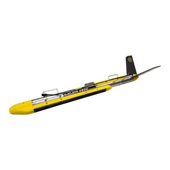
CHAPTER 1 Overview 1.2.1 Towfish The towfish, which is shown in Figure 1-1, consists of a negatively buoyant stainless steel housing with attached port and starboard sonar transducers, a nose cone and a tail cone with stabilizing fins. The housing contains the sonar electronics, a downlink demultiplexer for control signals and an uplink multiplexer for sonar and sensor data. -
Page 21: Figure 1-1: Towfish
Stabilizing fins Tow bracket Carrying handle (4) Jumper cable Tail cone Safety cable tab Stainless steel housing Port transducer Nose cone Figure 1-1: Towfish... -
Page 22: Laptop Computer
CHAPTER 1 Overview Figure 1-2: SP-III TPU 1.2.3 Laptop Computer The laptop computer, which includes the Windows operating system and SonarPro installed, is the control and display interface. The computer is set up in a client- server format, allowing for flexible and expandable system configurations with multiple computers connected over a TCP/IP fast Ethernet network, all sharing the sonar data. -
Page 23: Sonarpro Workstation
Equipment Figure 1-3: Rack Mount TPU used in conjunction with a NMEA $ZDA message input to add an accurate time stamp to the data. The TPU provides power and downlink commands to the towfish by combining 200 VDC with FSK control signals for transmission over the coaxial conductor in the tow cable. -
Page 24: Tow Cable
CHAPTER 1 Overview Figure 1-4: SonarPro Workstation 1.2.6 Tow Cable The standard tow cable is 50 meters long, Kevlar reinforced and includes a single coaxial conductor. It is used to tow and to provide power to the towfish, to transmit commands from the SP-III TPU to the towfish, and to transmit sonar and sensor data from the towfish to the SP-III TPU. - Page 25 CHAPTER 2: S PECIFICATIONS This chapter includes the physical and performance specifications for the main components of the Series 4900 Sonar System. NOTE Specifications are typical and subject to change without notice. Sonar System Beams: 1 port and 1 starboard Sonar channels: Sonar frequencies: 455 kHz and 900 kHz;...
-
Page 26: Chapter 2 Specifications
CHAPTER 2 Specifications Range: 10, 15, 20, 25, 30, 40, 50, 60, 75, 100, 120, 150, and 200 meters at 455 kHz 10, 15,20, 25,30, 40, 50, 60, and 75 meters at 900 kHz Near nadir coverage: 25% of altitude per side SP-III TPU Size: 50.24 cm (19.78 in.) wide... -
Page 27: Laptop Computer
Laptop Computer Laptop Computer Size: 39.0 cm (15.6 in.) wide 3.8 cm (1.5 in.) high 30.0 cm (11.8 in.) deep Weight: 3.2 kg (7.0 lb) Operating system: Windows Applications software: SonarPro SonarPro Workstation Size: 8.9 cm (3.5 in.) H 48.3 cm (19.0 in.) W 43.2 cm (17.0 in.) D Weight: 22.8 kg (50 lb) -
Page 28: Sensors
CHAPTER 2 Specifications Power requirements: Provided from SP-III TPU or Rack Mount TPU Weight in air: 24.7 kg (54.5 lb) Weight in water: 13.5 kg (29.7 lb) 2.6.2 Sensors Compass Heading accuracy, level: ±0.5∞ RMS Heading accuracy, tilted: ±1.0∞ RMS, <±30∞ tilt ±1.5∞... -
Page 29: Armored Coaxial Tow Cable (0.322-Inch)
Tow Cables 2.7.2 Armored Coaxial Tow Cable (0.322-inch) Type: Double layer, counter helical, galvanized improved plow steel (GIPS) Conductors: Coaxial copper Diameter (OD): 8.2 mm (0.322 in.) Breaking strength: 42.7 kN (9600 lbf) Working load: 10.7 kN (2400 lbf) Operational length: 1500 m (4920 ft) maximum Voltage rating: 1200 VDC... -
Page 31: Chapter 3: Setup And Test
If any items are damaged or missing, immediately contact Klein Marine Systems, Inc. or your KMS sales representative. In addition, record the serial numbers for the towfish, the SP-III TPU or Rack Mount TPU, and the laptop or SonarPro Workstation. -
Page 32: Locating The Topside System Components
CHAPTER 3 Setup and Test Locating the Topside System Components The SP-III TPU or Rack Mount TPU and the laptop computer or SonarPro Workstation should be located in an area that is protected from weather and spray and where the temperatures are consistently between 0°C and 35°C (32°F and 95°F). -
Page 33: Grounding
Towfish Setup 3.3.1 Grounding It is important that the Series 4900 Sonar System be well grounded to minimize potential hazards to the operator and electrical interference from other equipment. A good ground for the system is a low impedance, well conducted path to sea water. -
Page 34: Connecting The Tow Cable To The Towfish
CHAPTER 3 Setup and Test 3.4.2 Connecting the Tow Cable to the Towfish When connecting the tow cable to the towfish, refer to APPENDIX D: “Rigging Guide” for instructions. Instructions are provided for a towfish without an optional K-wing depressor and for a towfish with a K-wing I or K-wing II depressor. WARNING Before connecting the tow cable, verify that the SP-III TPU or Rack Mount TPU is turned off and that its power cord is disconnected. -
Page 35: Topside System Connections
Topside System Connections Grasp the body of each connector at the towfish and gently pull them apart. Do not pull on the cables to separate the connectors. Always hold the body of the connectors. After separating the connectors, put a thin coating of silicone grease on the rubber section of the connector pins. -
Page 36: Figure 3-1: Sp-Iii Tpu Side Panel
D/C POLARITY NAV connector indicator T/F TRIG indicator LOCK LOSS DEBUG connector indicator T/F PWR RESP TRIG indicator MAG connector indicator indicator TOWFISH D/C-A/C connector switch 120/240 VAC connector T/F TRIG EXT TRIG IN 1PPS connector RESP TRIG 12 VDC connector connector connector... -
Page 37: Rack Mount Tpu Connections
Topside System Connections NAV: DB9 male RS-232 serial port connector that connects to a shipboard navigation system and inputs NMEA 0183 message sentence formats. The baud rate is 4800. 120/240 VAC: 3-pin bulkhead connector that connects to an 88–264 VAC, 47–63 Hz power source. 12 VDC: 4-pin bulkhead connector that connects to a 12 VDC power source. -
Page 38: Rack Mount Tpu Back Panel
LAN connector TRIG A connector T/F TRIG connector AC INPUT connector TOWFISH connector MAG connector NAV connector 1PPS IN connector NOTE: Connectors that are not called out are not used or are for factory use only. Figure 3-2: Rack Mount TPU Back Panel... -
Page 39: Sonarpro Workstation Connections
Connecting the Topside System Components 3.5.3 SonarPro Workstation Connections All the connections to the SonarPro Workstation are made to connectors on the back panel which is shown in Figure 3-3. The SonarPro Workstation connectors are the following: USB: USB connectors (4, plus 2 on the front panel). Any two connect to the keyboard and the mouse. -
Page 40: Figure 3-3: Sonarpro Workstation Back Panel
AC INPUT connector ON/OFF switch DVI connector ETHERNET connector (2) and circuit breaker USB connector (4) NOTE: Connectors that are not called out are not used or are available for optional use. Figure 3-3: SonarPro Workstation Back Panel... -
Page 41: Table 3-2: Towfish Jumper Cable Connector Pinout
3-11 Connecting the Topside System Components For the connector pinouts and pin orientations for each of the connectors on the SP-III TPU side panel, refer to Table 3-3 through Table 3-8. For the connector pinout and orientation of the towfish jumper cable connector, refer to Table 3-2. Table 3-2: Towfish Jumper Cable Connector... -
Page 42: Table 3-3: Lan Connector Pinouts
Table 3-3: Table 3-4: 12 VDC Connector Pinouts Connector Pinouts FUNCTION FUNCTION Return +12 VDC Table 3-5: Table 3-6: 120/240 VAC TOWFISH Connector Pinouts Connector Pinouts FUNCTION FUNCTION Neutral 200 VDC Power and Telemetry Shield Line Table 3-7: Table 3-8: NAV, DEBUG T/F TRIG, and MAG Connector... -
Page 43: Connecting The Rack Mount Tpu And The Sonarpro Workstation
3-13 Connecting the Topside System Components Connect the tow cable to the TOWFISH connector on the SP-III TPU. Connect the AC power cable to the 120/240 VAC connector on the SP-III TPU and to the AC power source, or connect the DC power cable to the 12 VDC connector on the SP-III TPU and to a 12 VDC power source, or both. - Page 44 3-14 CHAPTER 3 Setup and Test Connect a GPS to the NAV connector on the Rack Mount TPU. A user supplied RS-232 serial cable is required where one end is terminated with a DB9 female connector and the other end is as required by the navigation system.
-
Page 45: Topside System Controls And Indicators
3-15 Topside System Controls and Indicators Topside System Controls and Indicators The SP-III TPU includes controls and indicators on the side panel. The Rack Mount TPU and the SonarPro Workstation include controls and indicators on the front panels. The SonarPro Workstation also has its power switch on the back panel. -
Page 46: Figure 3-4: Rack Mount Tpu Front Panel
TOWFISH indicators STATUS indicators POWER indicator POWER switch EQUALIZATION indicators SYS READY indicator OPTIONS indicators T/F POWER indicator Figure 3-4: Rack Mount TPU Front Panel... - Page 47 3-17 Topside System Controls and Indicators SYS READY: Green LED that will flash while the Rack Mount TPU and the towfish are powering up and then remain on when the Rack Mount TPU is ready to link with SonarPro on the SonarPro Workstation. T/F POWER: Blue LED that is on when power is being output to the towfish.
-
Page 48: Sonarpro Workstation Controls And Indicators
3-18 CHAPTER 3 Setup and Test 3.7.3 SonarPro Workstation Controls and Indicators Most of the SonarPro Workstation controls and indicators are on the SonarPro Workstation front panel which is shown is Figure 3-5. Also shown is the location of the DVDRW optical drive. The SonarPro Workstation controls and indicators are the following: ON/OFF switch: Rocker switch/circuit breaker that switches AC... -
Page 49: Figure 3-5: Sonarpro Workstation Front Panel
HARD DRIVE ACTIVITY indicator ETHERNET indicator POWER ON indicator DVDRW optical drive RESET switch POWER switch USB connector (2) Figure 3-5: SonarPro Workstation Front Panel... - Page 50 3-20 CHAPTER 3 Setup and Test Verify that the tow cable is connected to the SP-III TPU or Rack Mount TPU and the towfish. Turn on the laptop computer or the SonarPro Workstation and wait for the Windows desktop to appear. NOTE For an SP-III TPU, should the DC power cord be connected with the polarities reversed, the D/C POLARITY indicator will illuminate when the A/C-D/C switch is switched to D/C.
-
Page 51: Activating And Testing The System At Sea
3-21 System Activation and Test Perform a rub test on the port and starboard transducers to confirm that the receiver mode is operating properly. Do this test by vigorously rubbing each transducer, one at a time, while observing the Sonar Viewer window in SonarPro for returns. - Page 52 3-22 CHAPTER 3 Setup and Test • Turn on the Rack Mount TPU. The POWER and EQUALIZATION IN PROCESS indicators should illuminate, and the SYS READY indicator should flash. Then after approximately 1 minute, the EQUALIZATION IN PROCESS indicator should turn off, the EQUALIZATION COMPLETE and T/F POWER indicators should turn on, the SYS READY indicator should stop flashing and remain on, and the STATUS TRIGGER indicator should begin flashing at the ping rate of the sonar.
-
Page 53: Chapter 4: Equipment Maintenance
CHAPTER 4: E QUIPMENT AINTENANCE This chapter provides instructions for maintaining the Series 4900 Sonar System on a daily, weekly and long term basis. In addition, instructions are provided for disassembling and reassembling the towfish and removing and installing the transducers. -
Page 54: Weekly Maintenance Checklist
CHAPTER 4 Equipment Maintenance Keep the tow cable plugged into the towfish, or use dummy plugs on the tow cable and towfish to keep the connectors from exposure to the salt atmosphere. Remember to put a thin film of silicone grease, such as Dow-Corning 4, on the rubber portion of the underwater connector every time the towfish is disconnected. -
Page 55: Disassembling And Reassembling The Towfish
Disassembling and Reassembling the Towfish Disassembling and Reassembling the Towfish For troubleshooting purposes and for repair, it may be required to remove and replace major components of the towfish. Instructions are provided in the following pages for the disassembly of the towfish and the removal of the towfish electronics chassis and the transducers. -
Page 56: Figure 4-2: Removing The Tail Cone
CHAPTER 4 Equipment Maintenance Pull the tail cone away Jumper cable from the towfish housing, and then reach inside the housing and disconnect the jumper cable. Figure 4-2: Removing the Tail Cone Set the tail cone aside, and then remove the tail cone retaining bolt which is shown in Figure 4-3. -
Page 57: Removing The Nose Cone
Disassembling and Reassembling the Towfish Using the 8-mm hex key, loosen the nose cone retaining bolt and remove the nose cone. The bolt is accessed from the tip of the nose. Figure 4-4: Removing the Nose Cone Disconnect the two transducer cables. -
Page 58: Tightening The Locking Screws In The Towfish Housing Forward End Cap
CHAPTER 4 Equipment Maintenance Using the 5-mm hex key, tighten the three locking screws in the towfish housing forward end cap. Locking screw (3) Figure 4-6: Tightening the Locking Screws in the Towfish Housing Forward End Cap Screw the tail cone retaining bolt into the threaded hole in the middle of the forward end... -
Page 59: Figure 4-8: Pulling The Forward End Cap Out Of The Towfish Housing
Disassembling and Reassembling the Towfish Grasp the tail cone retaining bolt and carefully pull the forward end cap out of the towfish housing. Figure 4-8: Pulling the Forward End Cap out of the Towfish Housing Set the forward end cap aside as shown in Figure 4-9. -
Page 60: Figure 4-10: Tightening The Locking Screws In The Towfish Housing Aft End Cap
CHAPTER 4 Equipment Maintenance Using the 5-mm hex key, tighten the three locking screws in the towfish housing aft end cap. Locking screw (3) Figure 4-10: Tightening the Locking Screws in the Towfish Housing Aft End Cap Screw the tail cone retaining bolt into the threaded hole in the middle of the aft end cap. -
Page 61: Reassembling The Towfish
Disassembling and Reassembling the Towfish 4.3.2 Reassembling the Towfish To reassemble the towfish: Verify that the O-rings on both the forward and aft end caps are clean and free of dirt or scratches. Also use a lint-free cloth or paper towel to clean the O-ring surfaces inside the towfish housing and apply a light coat of silicone grease to these surfaces. -
Page 62: Aligning The Locking Screws Before Inserting The Forward End Cap
4-10 CHAPTER 4 Equipment Maintenance Figure 4-13: Aligning the Locking Screws before Inserting the Forward End Cap Slide the nose cone into the towfish housing, aligning Slot the locator pin on the nose Locator pin cone with the slot in the housing and threading the nose cone retaining bolt into the forward end cap as... -
Page 63: Removing The Transducers
4-11 Disassembling and Reassembling the Towfish 4.3.3 Removing the Transducers To remove the transducers: Perform Steps 1 through 4 in “Disassembling the Towfish” on page 4-3. Using the 4-mm hex key, remove the eight socket head cap screws securing either transducer assembly to the towfish housing. -
Page 64: Assembly
4-12 CHAPTER 4 Equipment Maintenance Set the transducer assembly down with the transducer facing up. Using the 4-mm hex key, remove the four socket head cap screws on the face of the transducer, two on each end. Socket head cap screw (2 each end) Figure 4-17: Location of the Four Socket Head... -
Page 65: Installing The Transducers
4-13 Disassembling and Reassembling the Towfish 4.3.4 Installing the Transducers To install the transducers: Reverse Steps 2 through 7 in “Removing the Transducers” on page 4-11 for each transducer. Connect the two transducer cables, matching the colors with the connectors on the forward end cap. -
Page 67: Chapter 5: Technical Description
CHAPTER 5: T ECHNICAL ESCRIPTION This chapter provides an overall technical description of the Series 4900 Sonar System towfish, the SP-III TPU and the Rack Mount TPU electronics. This information, which includes block diagrams, printed circuit board descriptions, and chassis photos with callouts, is useful when performing any troubleshooting tasks and when installing optional equipment. -
Page 68: Figure 5-1: The Series 4900 Sonar System Towfish Electronics Block Diagram
Figure 5-1: The Series 4900 Sonar System Towfish Electronics Block Diagram... -
Page 69: The Series 4900 Sonar System Towfish Electronics Chassis
Subsea Telemetry Transmitter board board 12 VDC Power Supply board Transition 12 VDC Power Filter board board Control Sensor Interface (CSI) Receiver board Compass board board Figure 5-2: The Series 4900 Sonar System Towfish Electronics Chassis... - Page 70 CHAPTER 5 Technical Description Control Sensor Interface (CSI) board. The CSI board interconnects the Transmitter board, the Receiver board, the Telemetry board, the sensors, and the ASCII I/O ports. Specifically, the CSI board performs the following functions: • Provides a central connection point for various system command interconnects.
-
Page 71: Transducer Arrays
Towfish Transition board. The Transition board provides the means to connect the large gauge wires from the RX PORT and RX STBD bulkhead connectors on the end cap to the Receiver board’s 50 pin ribbon cable and to the Transmitter board’s 3-pin connectors. -
Page 72: Sp-Iii Tpu
CHAPTER 5 Technical Description SP-III TPU The SP-III TPU provides signal processing along with the system control and data telemetry functions. The printed circuit boards, along with their corresponding part numbers, are the following: • Demux board 14105208-04 • CPU board 14105873 •... -
Page 73: Figure 5-3: Sp-Iii Tpu Electronics Block Diagram
Figure 5-3: SP-III TPU Electronics Block Diagram... -
Page 74: Figure 5-4: Sp-Iii Tpu Electronics
Panel Interconnect board Power Integration 12 VDC board power supply CPU board (under Telemetry Demux board board) Topside Telemetry board (under Telemetry board) Figure 5-4: SP-III TPU Electronics... -
Page 75: Rack Mount Tpu
Rack Mount TPU Rack Mount TPU A block diagram depicting the functional relationships of all of the printed circuit boards in the Rack Mount TPU electronics is shown in Figure 5-5. These boards are located in the Rack Mount TPU electronics chassis as shown in Figure 5-6. The printed circuit boards, along with their corresponding part numbers, are the following: •... -
Page 76: Figure 5-5: The Series 4900 Sonar System Rack Mount Tpu Electronics Block
Figure 5-5: The Series 4900 Sonar System Rack Mount TPU Electronics Block Diagram... -
Page 77: Figure 5-6: The Series 4900 Sonar System Rack Mount Tpu Electronics Chassis
CPU board 200V Power Filter board Demultiplexer board 12V Power Filter board 12V Power Supply board Topside Telemetry board High Voltage LED board Power Supply board Figure 5-6: The Series 4900 Sonar System Rack Mount TPU Electronics Chassis... - Page 78 5-12 CHAPTER 5 Technical Description Topside Telemetry board. The Topside Telemetry board provides the cable interface for the Rack Mount TPU. Specifically, the Topside Telemetry board performs the following functions: • Separates the uplink data signals, the downlink command signals and the towfish power.
-
Page 79: Appendix A: Notes On Handling Tow Cables
APPENDIX A: N OTES ON ANDLING ABLES A few methods on how to safely unreel tow cables are provided in this appendix. In addition, how cable kinking can occur is identified along with what can result from this condition. A.1 Unreeling Tow Cable The reel should be revolved and the rope taken off the way it was put on the reel as shown in Figure A-1 for two effective methods. -
Page 80: A.2 Uncoiling Tow Cable
APPENDIX A Notes on Handling Tow Cables A.2 Uncoiling Tow Cable Remove ties and roll the coil along the ground so the rope lies straight. There will be no twist or kink in the cable if these instructions are followed. CAUTION If the reel and coil do not revolve freely, it will cause the cable to twist as each turn is taken off. -
Page 81: A.3.2 Effect Of Cable Kinking
Cable Kinking Cable Loop Cable Kink Figure A-3: Cable Loop and Kink A.3.2 Effect of Cable Kinking The effect of kinking is shown in Figure A-4. The cable is permanently damaged Figure A-4: Damaged Cable A.3.3 Result of Cable Kinking The result of cable kinking is that strands and wires are displaced, creating uneven tension which causes excessive wear at the point of the kink. -
Page 83: Appendix B: Configuring And Updating The Sp-Iii Tpu
• Download and install software updates to the SP-III TPU. B.1 Starting Linux TPU Updater Linux TPU Updater is started by double-clicking the Linux TPU Updater icon on the Windows desktop. The Klein Linux TPU Updater dialog box will open as shown Figure B-1. Figure B-1:... -
Page 84: B.2 Querying Or Changing The Sp-Iii Tpu Ip Address
7. From the Rate drop-down list box, select the baud rate of the SP-III TPU’s NAV serial port, or select Determine Automatically to have Linux TPU Updater find the rate. The Klein Linux TPU Updater dialog box opens with the current IP address displayed in the text box as shown in Figure B.3. -
Page 85: B.3 Editing The Sp-Iii Tpu Startup File
Editing the SP-III TPU Startup File Figure B-3: The Klein Linux TPU Updater Dialog Box with Current TPU IP Address Displayed 8. Enter the new address in the Enter New IP Address text box, and then click Set TPU IP Address A window opens confirming the change: B.3 Editing the SP-III TPU Startup File... -
Page 86: B.4 Updating The Sp-Iii Tpu Software
D/C for DC operation. 4. Start Linux TPU Updater. The Klein Linux TPU Updater dialog box opens. 5. Enter the SP-III TPU IP address in the Enter TPU IP Address text box if it is different than the default address, or click if it is the default. - Page 87 Updating the SP-III TPU Software 6. Click Update TPU Software . An dialog box opens that enables file selection. 7. Select and open the update file to download and install. The file is downloaded to the SP-III TPU and installed, and the SP-III TPU software restarts.
-
Page 89: Appendix C: Compass Calibration
APPENDIX C: C OMPASS ALIBRATION This appendix provides the procedure for calibrating the 14106073 MTI3 compass. C.1 Overview In this procedure SonarPro is used to control a calibration procedure once the compass is completely installed in the towfish. The procedure may be performed in the factory or in the field. - Page 90 APPENDIX C Compass Calibration 9. Enter the following command to start the calibration process. $SI:SMC1$CCB 10. Perform the calibration movements: • Make sure the towfish is as far away from large metal objects and power wiring as possible. • Move the towfish to point in as many locations as possible for approximately three minutes.
-
Page 91: Table C-1: Iccstat Result Codes
Procedure Table C-1: ICCSTAT Result Codes ICCSTAT RESULT Successful calibration Too much disturbance (noise) Not enough data Both 1 and 2 above 17. If the calibration is successful, enter the following command to write the results to the sensor memory: $SI:SMC1$CCS... -
Page 93: Appendix D: Rigging Guide
APPENDIX D: R IGGING UIDE This appendix includes the towfish rigging guides for a towfish without an optional K-wing depressor and for a towfish with a K-wing I or K-wing II depressor. -
Page 97: Appendix E: Drawings
APPENDIX E: D RAWINGS This appendix includes the following outline drawings. They are provided for reference purposes. Drawing 14605656: Outline, S4900 Towfish Drawing 14605270: Outline, Splashproof II and III Drawing 14605729: Outline, Rack Mount TPU... -
Page 101: Appendix F:towfish Towing Characteristics
APPENDIX F:T OWFISH OWING HARACTERISTICS This appendix describes the towing characteristics of the towfish as graphical plots of the towfish depth versus tow cable length for various towfish speeds. - Page 102 APPENDIX F Towfish Towing Characteristics Series 4900 Sonar System Operations and Maintenance Manual P/N 11210091, Rev. 02...
- Page 104 APPENDIX F Towfish Towing Characteristics Series 4900 Sonar System Operations and Maintenance Manual P/N 11210091, Rev. 02...
- Page 106 APPENDIX F Towfish Towing Characteristics Series 4900 Sonar System Operations and Maintenance Manual P/N 11210091, Rev. 02...
-
Page 109: Appendix G: System Setup Diagram With Acoustic
APPENDIX G: S YSTEM ETUP IAGRAM WITH COUSTIC OSITIONING YSTEM This appendix comprises the system setup diagram shown in Figure G-1 for installations with an acoustic positioning system. -
Page 110: Positioning System
APPENDIX G System Setup Diagram with Acoustic Positioning Sys- Acoustic Tracking Navigation System Unit NMEA 0183 4800 baud Formats: GGA&VTG GLL&VTG or Depth Acoustic Positioning System Output Format: RMC and TLL or GLL&VTG and TLL or GGA&VTG and TLL Towfish Ethernet port Laptop computer...
Need help?
Do you have a question about the 4900 Series and is the answer not in the manual?
Questions and answers