
Related Manuals for Klein 3900 Series


Summary of Contents for Klein 3900 Series
- Page 1 3900 S ERIES ONAR YSTEM Operations and Maintenance Manual P/N 11214510, Rev. 02 11 Klein Drive Salem, NH 03079-1249 U.S.A. Tel: (603) 893-6131 Fax: (603) 893-8807 www.KleinMarineSystems.com...
- Page 2 This document contains proprietary information, and such information may not be disclosed to others for any purpose or used for any manufacturing purpose without expressed written permission from Klein Marine Systems, Inc. (KMS). The information provided is for informational purposes only and is subject to change without notice.
- Page 3 CAUTION When the towfish is close to the sea floor, the 900-kHz bottom tracking (altitude) performance is not exact. Klein Marine Systems, Inc. advises extreme caution when operating the towfish at altitudes of less than 4 meters (13 feet).
-
Page 4: Table Of Contents
Table of Contents Table of Contents ..........iv List of Figures . - Page 5 CHAPTER 2: Specifications ....... 2-1 Sonar System ........2-1 Sonar Transceiver and Processing Unit (TPU) .
- Page 6 Mechanical Installation of the TPU and Computer ..3-2 3.2.1 Location ......... 3-2 3.2.2 Mounting .
- Page 7 Setting up and Connecting the Splashproof TPU ... 5-9 5.2.1 Included Accessories ......5-10 5.2.2 Connecting Power .
- Page 8 viii B.6.5 Auxiliary and Compass Commands ....B-19 B.6.6 System 5900 MUX Commands ..... . B-20 B.6.7 System 5900 DSP Commands .
-
Page 9: List Of Figures
List of Figures Figure 1-1: Splashproof TPU ..........1-3 Figure 1-2: Towfish . - Page 10 List of Tables Table 1-1: Towfish Connector—at Towfish ........1-8 Table 3-1: TPU Power Cord Wiring .
-
Page 11: Sonar System Warranty
Sonar System Warranty What Is Covered LIMITED WARRANTY Subject to the conditions set forth below, equipment sold by Seller is warranted against defects in materials and workmanship, and Seller will repair or exchange any parts proven to be malfunctioning under normal use for one year (12 months) from the date of Delivery as follows: a) SONAR and other associated manufactured products, with the following exceptions:... -
Page 12: Conditions Of Warranty
Conditions Of Warranty a) Seller’s warranty policy does not apply to equipment which has been subjected to accident, abuse, or misuse, shipping damage, alterations, incorrect and/or non- authorized service or equipment on which the serial number plate has been altered, mutilated or removed. b) A suitable proof of purchase, such as, a paid commercial invoice, an installation certificate signed by Seller or an authorized agent must be made available to Seller or Seller’s authorized servicing agent at the time of the Warranty Service. -
Page 13: Changes, Errors And Ommissions
AROSE. Changes, Errors And Ommissions Klein Marine Systems, Inc. reserves the right to make changes to the design or specifications at any time without incurring any obligation to modify previously delivered sonar systems. In addition, while considerable effort has been made to ensure that the information in this manual is accurate and complete, Klein Marine Systems, Inc. -
Page 14: Software License Agreement
Software License Agreement This Software License Agreement is provided by Klein Marine Systems, Inc. © (KMS) for end users of SonarPro software for the KMS Series 3000, UUV-3500, 3900, 4900, 5000, 5000 V2, 5900, HydroChart 3500, HydroChart 5000, and D3500TF Sonar Systems. - Page 15 BATHYMETRIC PROCESSING ATTRIBUTION: Bathymetric processing derived from DGA/GESMA publication in IEEE OCEAN'S 05 Europe Conference Proceedings: "Bathymetric Sidescan Sonar: a System Dedicated to Rapid Environment assessment, ref: 10.1109/OCEANSE.2005.1511695. EXPORT RESTRICTIONS: You agree that you will not export or re-export the Software or accompanying documentation (or any copies thereof) or any products utilizing the Software or such documentation in violation of any applicable laws or regulations of the United States or the country in which you obtained them.
-
Page 16: Preface
ENTIRE AGREEMENT: This License Agreement sets forth the entire understanding and agreement between you and KMS supersedes all prior agreements, whether written or oral, with respect to the Software, and may be amended only in a writing signed by both parties. Preface The Series 3900 Sonar System is a towed single beam sonar comprising a towed underwater platform and a topside system. -
Page 17: Note, Warning, Caution, And Shock Hazard Notices
SHOCK HAZARD Identifies a potential electrical shock hazard that could cause personal injury or death to yourself or to others. Customer Service KMS technical support can be contacted using any of the following means: Mail Klein Marine Systems, Inc. 11 Klein Drive Salem, NH 03079 Email Klein.Mail@KleinMarineSystems.com... -
Page 19: Chapter 1: Overview
CHAPTER 1: O VERVIEW The Series 3900 Sonar System displays sonar data on a high resolution monitor and will store data on both the hard disk drive and a CD for high capacity storage. Many optional accessories may be added to the basic system for special situations or applications. -
Page 20: Computer Display And Control Unit
• Small, lightweight and simple to operate and maintain • Interfaces to third party processors and LAN networks • Standard operating depth of 200 meters • Compatible with all Klein Marine Systems towing accessories and lightweight cables • Low cost Series 3900 Sonar System Operations and Maintenance Manual 11214510, Rev. -
Page 21: Physical Description
Physical Description Physical Description The Series 3900 Sonar System consists of two major subsystems: the surface equipment and the subsurface equipment. 1.3.1 Surface Equipment The surface subsystem comprises the TPU, the Computer Display and Control Unit (computer), and the Ethernet Hub. Transceiver and Processing Unit (TPU). -
Page 22: Subsurface Equipment
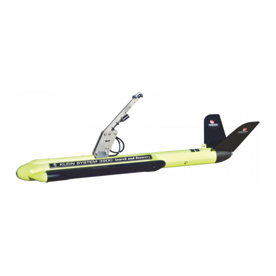
CHAPTER 1 Overview 1.3.2 Subsurface Equipment The subsurface equipment comprises the towfish, as shown in Figure 1-2, and a tow cable. Towfish Figure 1-2: The Towfish consists of a negatively buoyant tow body containing Towfish. port and starboard sonar transducers, processing and control electronics for sonar operation, a downlink demultiplexer for control signals, and an uplink multiplexer for sonar and auxiliary sensor data. -
Page 23: Theory Of Operation
Theory of Operation Theory of Operation This section provides a detailed functional description of the Series 3900 Sonar System operation. 1.4.1 Introduction The Series 3900 Sonar System is a single beam side-looking sonar intended for high resolution survey use. The Series 3900 departs from previous single beam systems in that the swath forming process is implemented digitally using digital signal processing (DSP), rather than analog delay lines, phase shifters, or multipliers and adders. - Page 24 CHAPTER 1 Overview NOTE The transducers are side specific and are not interchangeable. The two transducer arrays are each composed of piezoelectric ceramic sub-arrays that operate as both transmit and receive elements. Each set of sub-arrays is arranged into a continuous line array spanning an overall aperture of 48 centimeters.
- Page 25 Theory of Operation Multiplexer board Tow Cable Power Splitter Data and 200 VDC Towfish Power Supply Multiplexed 200VDC Data +5 +15 Multiplexer High Frequency Transceiver Board (900 kHz) Port Transducer Data Starboard Transducer Low Frequency Transceiver Board (445 kHz) Transmit Control TVG Generator Heading, Pitch, Roll Module Pressure Sensor (Optional)
-
Page 26: Figure 1-4: Towfish Connector-At Towfish
CHAPTER 1 Overview The Multiplexer board digitizes the signals from each of Multiplexer board. the transducer sub-array channels along with the signals from the sensors, encodes the data, and transmits a high baud rate digital data stream to the TPU via the tow cable. -
Page 27: Transceiver And Processing Unit
Theory of Operation 1.4.3 Transceiver and Processing Unit The TPU provides signal processing along with the system control and data telemetry functions. The TPU is composed of two circuit boards: an embedded CPU board and a Demultiplexer board. The TPU also contains a 200-volt towfish power supply and a TPU power supply. - Page 28 1-10 CHAPTER 1 Overview The data from the towfish arrives in serial NRZ format and is conditioned and input to the clock recovery circuit. The recovered clock is used to strobe the serial data into a line decoder. The decoded data is converted to parallel format and output the front panel connector.
- Page 29 CHAPTER 2: S PECIFICATIONS This chapter includes the physical and performance specifications for the main components of the Series 3000 Sonar System. NOTE Specifications are typical and subject to change without notice. Sonar System Sonar channels: 900 kHz nominal Sonar frequencies: 445 kHz nominal Toneburst, independent pulse controls Transmission pulse:...
-
Page 30: Chapter 2 Specifications
CHAPTER 2 Specifications Sonar Transceiver and Processing Unit (TPU) 2.2.1 TPU Operation The only operator control on the TPU is the main power switch. 2.2.2 Towfish Input/Output Quantity: Type N Connector: 2.2.3 RS-232 COM 1, COM3 and COM4 Ports Quantity: 9600 baud Baud rate: 9-pin DSUB for receiving sensor data... -
Page 31: Computer Display And Control Unit
Computer Display and Control Unit Computer Display and Control Unit For specifications on the Computer Display and Control Unit, please refer to the manufacturer's manual. Ethernet Hub For specifications on the Ethernet Hub, please refer to the manufacturer's manual. Towfish 2.5.1 General Modular plug-in... -
Page 32: Multiplexer
CHAPTER 2 Specifications 2.5.6 Multiplexer Pulse code modulation (PCM) Modulation format: Time division multiplexing (TDM) Multiplexing format: Number of channels: Data rate: 1.544 Mb/s B8ZS Data format: Better than 1x10 (before correction) Bit error rate: 2.5.7 Power Powered from the TPU; no additional Input power: power required 2.5.8... -
Page 33: Pressure Sensor (Optional)
Tow Cable 2.5.11 Pressure Sensor (Optional) Selectable Pressure range: ±0.10% Accuracy: Tow Cable Polyurethane jacketed coaxial, Kevlar Type: reinforced Conductors: Coaxial copper Diameter (OD): 1.156 cm (0.455 in.) 2270 kg (5000 lb) Breaking strength: Working load: 454 kg (1000 lb) 3000 m maximum Operational length: Voltage rating:... -
Page 35: Chapter 3: Preparation For Use
Remove the computer from the shipping container, and set it on a sturdy, flat surface. Inspect the computer for signs of damage. If there is any damage or if any items are missing, immediately contact Klein Marine Systems, Inc. or your KMS sales representative. Record the serial numbers of the computer modules. -
Page 36: Unpacking The Towfish
The tow cable is shipped on a cable palette or reel. Inspect the cable for damage. If there is any damage or if any items are missing, immediately contact Klein Marine Systems, Inc. or your KMS sales representative. The TPU end of the cable has a Type N connector. -
Page 37: Power Connection
Power Connection Power Connection The Series 3000 requires AC power to operate. The power source requirements are 115 VAC, 50–60 Hz, single phase or 230 VAC, 50–60 Hz. The system is designed to protect against over and under voltage and transient spikes. However, it is always best to check the power source carefully before operating the equipment. -
Page 38: Power Line Fuse
CHAPTER 3 Preparation for Use TPU Power Cord Wiring Table 3-1: COLOR FUNCTION Yellow/green Ground (earth) Blue Neutral Brown After checking the power source, and modifying the power cord if required, connect the TPU to AC power. 3.3.2 Power Line Fuse The main AC power input line is protected by two 2-A, 5 x 20-mm slow-blow fuses rated for 250 volts (P/N 13000045). -
Page 39: Grounding
Towfish Setup 3.3.4 Grounding It is important that the TPU be well grounded to minimize potential hazards to the operator and electrical interference from other equipment. A good ground for the system is a low impedance, well conducted path to the sea water. Always check the quality of the electrical ground. - Page 40 CHAPTER 3 Preparation for Use WARNING In all of the procedures which follow, be sure that the power is turned off. Disconnect the TPU power cable from the power source. Failure to follow this practice may result in personal injury or damage to the towfish or the TPU electronics, or to both.
-
Page 41: Towfish And Optional Depressor Connection
If the tow cable is disconnected, however, it is very important that all connectors be properly maintained. Connectors must be kept clean and must remain out of the way of traffic while on deck. Klein Marine Systems, Inc. supplies dummy connectors which can be used to protect the underwater connectors on the towfish and cable when they are not mated to each other. -
Page 42: Quick Start Installation And Operating Guide
CHAPTER 3 Preparation for Use WARNING Power to the sonar system must be turned off prior to connection or disconnection of the tow cable to either the towfish or the TPU, as serious damage may occur to the sonar system electronics or injury may occur to the operator as a result of this action. -
Page 43: Deck Test
TPU. Make sure the GPS is outputting the NEMA 0183 format data string. It should contain GGA&VTG, GLL&VTG or RMC at 4800 baud. If 4800 baud is not available, contact contact Klein Marine Systems, Inc. technical support for assistance. -
Page 44: At-Sea Test
At-Sea Test CAUTION When the towfish is close to the sea floor, the 900-kHz bottom tracking (altitude) performance is not exact. Klein Marine Systems, Inc. advises extreme caution when operating the towfish at altitudes of less than 4 meters (13 feet). -
Page 45: Chapter 4: Equipment Maintenance
CHAPTER 4: E QUIPMENT AINTENANCE This chapter provides instructions for equipment maintenance and includes guides for taking care of the equipment on a daily, weekly, and long term basis. In addition, instructions are provided for replacing the fixed tail cone assembly. Maintenance General Comments Equipment used at sea is subjected to severe environmental and handling conditions. -
Page 46: Weekly Maintenance Checklist
CHAPTER 4 Equipment Maintenance 4. Keep the tow cable plugged into the towfish, or use dummy plugs on the tow cable and towfish to keep the connectors from exposure to the salt atmosphere. Remember to put a thin film of silicone grease, such as Dow-Corning 4, on the rubber portion of the underwater connector every time the towfish is disconnected. -
Page 47: Chapter 5: Splashproof Tpu
CHAPTER 5: S PLASHPROOF For use in open boat operations where exposure to rain and spray is likely, a lightweight, rugged, splashproof configuration of the Transceiver and Processor Unit (TPU) is available. The Splashproof TPU is similar to the rack mount configuration but is housed in a watertight, corrosion proof, high impact resistant Pelican Protector Case. -
Page 48: Optional Wireless Router-Series 3000 Only
CHAPTER 5 Splashproof TPU 5.1.1 Optional Wireless Router—Series 3000 Only The optional wireless router provides a wireless network connection to a computer running SonarPro with a wireless Ethernet device. This wireless router is capable of providing sufficient data bandwidth to support the data throughput of the system. -
Page 49: External Connections
General Description 5.1.3 External Connections The external connections to the Splashproof TPU are made on the connector panel which is shown in Figure 5-4. The connector panel is also shown inside the case cover in Figure 5-5. Most of the connectors on this panel are wired to internal connectors which connect to the Demultiplexer and CPU boards as shown in Figure 5-6 on page 5-6. -
Page 50: Figure 5-5: Inside The Cover Of The Splashproof Tpu Case
CHAPTER 5 Splashproof TPU View ports Connector panel Splashproof TPU Connector Panel Figure 5-4: Baffle Antenna Wireless Baffles router Connector panel Inside the Cover of the Splashproof TPU Case Figure 5-5: Series 3900 Sonar System Operations and Maintenance Manual 11214510, Rev. 02... -
Page 51: Operator Controls And Indicators
General Description 8-pin bulkhead connector for receiving navigation GPS IN: data. This connector is internally wired to a 9-pin DSUB connector that connects to the COM1 connector of the Demultiplexer board and to the output of the 12 VDC power supply. 3-pin bulkhead connector that connects to either a 120/240 VAC: 115 or 230 VAC, 50–60 Hz power source. - Page 52 VME chassis COM1 CABLE COM2 DEBUG TRIG 1 Demultiplexer board CPU board VOLTAGE SELECT switch (See CAUTIONS on page 5-10.) Low voltage Inverter power supply Figure 5-6: Front Panel of VME Chassis inside Splashproof TPU...
-
Page 53: Figure 5-7: Vme Backplane And Power Supply Connections Inside
VME chassis VME backplane Low voltage power supply VME fan 200 VDC power supply Transformer Power fuse 12 VDC power supply Choke GPS fuse Towfish fuse Figure 5-7: VME Backplane and Power Supply Connections inside Splashproof TPU... -
Page 54: Functional Components
CHAPTER 5 Splashproof TPU The connector panel also includes two view ports, as shown in Figure 5-4 on page 5-4, which allow you to view the setting of the VOLTAGE SELECT switch and the indicators on the Demultiplexer and CPU boards. For information about the indicators, refer to APPENDIX C: “General Setup and Configuration.”... -
Page 55: Setting Up And Connecting The Splashproof Tpu
Setting up and Connecting the Splashproof TPU The power fuse is in series with the main AC power input, the Power fuse. transformer input and the input to the low voltage power supply. It is a 2-A, 5 x 20-mm slow-blow fuse rated for 250 volts (P/N 13000045). The towfish fuse is in series with the 200 VDC output of the Towfish fuse. -
Page 56: Included Accessories
5-10 CHAPTER 5 Splashproof TPU 5.2.1 Included Accessories The following accessories are included with the Splashproof TPU: • AC power cord • DC power cord • Towfish jumper cable • GPS connector • TRIG connector • Waterproof LAN cable 5.2.2 Connecting Power The TPU can be powered from a 115 VAC, 230 VAC or 12 VDC power source. -
Page 57: Configuring The Wireless Network Connection For Windows 2000
5-11 Setting up and Connecting the Splashproof TPU 5.2.3 Configuring the Wireless Network Connection for Windows 2000 To configure the wireless network connection for Windows 2000: Refer to “Windows 2000 LAN Configuration Setup” on page C-10 and perform the first two steps to open the Network and Dial up Connection dialog box. -
Page 58: For Windows Xp
5-12 CHAPTER 5 Splashproof TPU 5.2.4 Configuring the Wireless Network Connection for Windows XP To configure the wireless network connection for Windows XP: Refer to “Windows XP LAN Configuration Setup” on page C-15 and perform the first two steps to open the Network Connection dialog box. Then in Step 3, right click Wireless Network Connection. -
Page 59: Activating The Splashproof Tpu
5-13 Activating the Splashproof TPU Activating the Splashproof TPU Activating the Splashproof TPU is similar to that of the rack mount TPU. SHOCK HAZARD Do not connect or disconnect the tow cable from the towfish or the TPU when power is on. Failure to follow this practice may result in personal injury and will damage the towfish or the TPU electronics, or both. -
Page 60: Specifications
5-14 CHAPTER 5 Splashproof TPU Specifications The specifications for the Splashproof TPU, except for those listed below, are the same as the rack mount TPU. Refer to CHAPTER 2: “Specifications,” for those specifications. NOTE Specifications are typical and subject to change without notice. 250 VA (nominal) Power consumption: 115 or 230 VAC, 50–60 Hz, manually... - Page 64 5-18 CHAPTER 5 Splashproof TPU Series 3900 Sonar System Operations and Maintenance Manual 11214510, Rev. 02...
- Page 68 5-22 CHAPTER 5 Splashproof TPU Series 3900 Sonar System Operations and Maintenance Manual 11214510, Rev. 02...
- Page 70 5-24 CHAPTER 5 Splashproof TPU Series 3900 Sonar System Operations and Maintenance Manual 11214510, Rev. 02...
-
Page 71: Appendix A: Notes On Handling Tow Cables
APPENDIX A: N OTES ON ANDLING ABLES A few methods on how to safely unreel tow cables are provided in this appendix. In addition, how cable kinking can occur is identified along with what can result from this condition. A.1 Unreeling Tow Cable The reel should be revolved and the rope taken off the way it was put on the reel as shown in Figure A-1 for two effective methods. -
Page 72: Uncoiling Tow Cable
APPENDIX A Notes on Handling Tow Cables A.2 Uncoiling Tow Cable Remove ties and roll the coil along the ground so the rope lies straight. There will be no twist or kink in the cable if these instructions are followed. CAUTION If the reel and coil do not revolve freely, it will cause the cable to twist as each turn is taken off. -
Page 73: Effect Of Cable Kinking
Cable Kinking Cable Loop Cable Kink Cable Loop and Kink Figure A-3: A.3.2 Effect of Cable Kinking The effect of kinking is shown in Figure A-4. The cable is permanently damaged Damaged Cable Figure A-4: A.3.3 Result of Cable Kinking The result of cable kinking is that strands and wires are displaced, creating uneven tension which causes excessive wear at the point of the kink. -
Page 75: Control Methods
APPENDIX B: TPU S OFTWARE NTERFACE ONTROL This appendix describes the various control and initialization procedures for the 3000, 5000 and 5900 Sonar System TPUs. The information in this document applies to TPU software version 5.3 and later. B.1 Control Methods Aside from control of the TPU via the Ethernet interface, the 3000/5000/5900 System may be controlled via NMEA messages or via a startup script file. - Page 76 APPENDIX B TPU Software Interface and Control RESPDIV {d = 0 - 15}. Sets the responder divisor to 2^d, where d = 0 – 15. A value of 15 turns the responder off. Default is 15 (off). RESPFREQ {d = 0 - 15}. Sets the responder frequency to 24 kHz + d * 500 Hz, where d = 0 –...
- Page 77 Startup Script TRIGOUTTYPE {d = 0,1}. Sets the Trig 1 Out trigger type. For normal installations the type is ‘0’ and a pulse is generated simultaneous with the towfish trigger. For the BlueFin AUV project the type should be set to ‘1’ which programs the port to output a pulse 31 milliseconds prior to the end of the range and at a rate such that the rate is maximum without exceeding 4 Hz.
- Page 78 DO NOT set this unless there is a fiber hooked up to the towfish and the fiber is properly terminated into the Klein FOI-01 Fiber Optic interface module. Setting this to ‘0’ deactivates the laser and activates the standard coaxial uplink.
- Page 79 Startup Script LBOGAIN {d = 0 – 3}. Along with the PREEMPHAIS variable (see above) this allows longer cables to be driven. The default value of ‘1’ provides for optimum performance on short to medium length cables. A value of ‘0’ decreases the uplink signal level by 6 dB.
- Page 80 APPENDIX B TPU Software Interface and Control towfish-motion-induced imbalance as well. A value between 50 and 200 is recommended. The default value of ‘0’ deactivates the new algorithm and uses the previous algorithm. MAXSAMPLES {d = 4096 – 65536} (System 5900 only). This limits the maximum number of samples generated per ping per beam.
- Page 81 Startup Script BLOVERRIDE {d = 0,1} (System 5000 only). Setting d = '1' limits the number of beams to 4. Setting d = '0' uses 5 beams. Note: If Bathy is enabled, number of beams is also limited to 4. Default is '0'. DECIMATIONMODE (System 5900 only).
- Page 82 APPENDIX B TPU Software Interface and Control SYS7KCONFIG33_64 {d = 0 - 0xFFFFFFF} (System 7XXX/5900 Only). Sets the channel configuration mask for channels 33 thru 64 to 'd'. Each bit in the mask enables a channel. For example 0x10000001 would enable channels 33 and 61 and disable all other channels.
- Page 83 Startup Script SUBBOTTOM {d = 0,1} (System 3000 Only). Setting d = '1' indicates the Towfish has the sub bottom profiler option. Enabling this option will cause the TPU to allow the sub bottom profiler to be enabled and sub bottom data collected.
- Page 84 "startup script" parameter field in the boot configuration. (See “TPU LAN Configuration Setup” on page C-23 for details on boot parameters.) For example: if the file is located in /klein, then the "startup script" parameter must be set to / klein/startup.ini.
-
Page 85: Remote Control
B-11 Remote Control SonarPro connected as master) then many of the commands will have no effect as there can only be one master and the software request to change a parameter will be rejected because there is an existing master. Many commands will echo the current setting if the data field is replaced with "?". - Page 86 B-12 APPENDIX B TPU Software Interface and Control Format the hard-drive. WARNING: this will erase all data. Only use if a new disk has been installed. Note: only supported if local disk-drive option installed. Set the length of the recorded files where d is the number of FLdddd: pings per file.
- Page 87 B-13 Remote Control Synchronize the internal clock. The <data> field is defined SC<data>: as follows: mm,dd,yyyy,hh,mm,ss,mmm which is month, day, year (4 digit), hours, minutes, seconds, and milliseconds. Prepare the system for shutdown. This puts the system in standby, stops any recording, and closes all files. When shutdown preparations are complete a status message is issued and the SD value is set to one.
-
Page 88: Snapshots
B-14 APPENDIX B TPU Software Interface and Control Turn velocity filter on|off, where d = 0 is off and d = 1 is on. VFd: Default is on. Set transmit waveform, where d = 0 is 50 µs, d = 1 is 100 µs WFd: and d = 2 is 200 µs. -
Page 89: Messages
B-15 Messages B.5 Messages B.5.1 Status Message Upon query of the system by the ST (status) command the system outputs a status message of the form: $PKLA,ST,RSdWFdRMdSMdDMdTPdVFdRCdSDdHDddERdd*hh<CR><LF> where the fields are as described above and HD is the percentage of hard drive space used and ER is an error/health monitoring byte (in ASCII hex representation) where zero indicates normal operation and a non-zero value indicates an error state defined as:... -
Page 90: Heartbeat Message
B-16 APPENDIX B TPU Software Interface and Control TPU watchdog. If this bit is set then a task may be locked. The TPU uses multi-threaded OS technology where multiple tasks are performed simultaneously. These tasks include acquiring the data, formatting it, parsing the sensor messages, handling navigation input, etc. -
Page 91: Towfish Commands
B-17 Towfish Commands NOTE The systems are available with a range of pressure sensors. This is the reason that absolute depth is not calculated by the TPU. B.6 Towfish Commands Although sonar control is normally performed using the Ethernet or NMEA interfaces, direct control of the towfish is possible. -
Page 92: 5000 System Transmitter Commands
B-18 APPENDIX B TPU Software Interface and Control Sets the uplink pre-emphasis amount where d = 0 – 7. See $MLd: the ‘PREEMPHASIS’ description in the startup script above for more information. This command can be used to fine tune the uplink for various cables. When the performance is optimized then this value can be incorporated into the startup script to initialize the pre- emphasis on boot-up. -
Page 93: System 5000 Actuator Commands
B-19 Towfish Commands B.6.3 System 5000 Actuator Commands For System 5000s equipped with an actuated wing, the wing actuator may be controlled using towfish commands. This is not recommended. The syntax is $MA<command><CR><LF> where <command> is a actuator control command. Refer to the appropriate actuator motor controller user's manual for more information on actuator commands. -
Page 94: System 5900 Mux Commands
B-20 APPENDIX B TPU Software Interface and Control Likewise for the 3000 System commands may be sent to an auxiliary sensor connected to the towfish auxiliary RS-232 port. The format of the commands is obviously specific to the sensor used. To issue a command to an auxiliary sensor the format would be $A<command><CR><LF>. -
Page 95: System 5900 Dsp Commands
B-21 Towfish Commands B.6.7 System 5900 DSP Commands The following commands are available to control the System 5900 DSP board: Resets the DSP. This command resets the DSP card to its $DR: initial default state. Selects the DSP test mode where d = 0 – 5. Test mode ‘0’ is $DTd: off. -
Page 96: System X000 Sub-Bottom Profiler (Sbp) Commands
B-22 APPENDIX B TPU Software Interface and Control Selects the transmitter mask. Each transmitter board is $XMdddd: comprised of 16 transmitters. Each transmitter can be individually masked. Each bit in the hex value dddd corresponds to a transmitter. For example $XM0001 would enable only the first transmitter. -
Page 97: Datalogger On/Off Commands
B-23 Towfish Commands B.6.10 Datalogger On/Off commands The 4 acceptable commands will be: Will turn power off to the sonar only. $PKLA,PC1: Will turn power off to the TPU only. $PKLA,PC2: Will turn power on to both the TPU and sonar. $PKLA,PC3: Will turn power off to both the TPU and sonar. -
Page 99: Appendix C: General Setup And Configuration
Basic System Requirements APPENDIX C: G ENERAL ETUP AND ONFIGURATION Included in this appendix are basic setup and configuration instructions along with other information useful for setting up the Series 3900 Sonar System. In addition, information is provided which can be helpful for system troubleshooting should problems occur, including instructions on how to verify operation of hardware components and transducers. -
Page 100: Figure C-1: Basic System Setup Diagram
APPENDIX C General Setup and Configuration Sample navigation strings: The preferred is RMC $GPRMC,101842.572,A,3318.577,N,07845.424,W,7.452,2 45.4,050202,0.0,E*72 $GPVTG,245.4,T,245.4,M,7.5,N,13.8,K*76 However the following can also be used $GPGLL,3446.8877,N,07849.0595,W,091739.00,A*1d $GPVTG,290.0,T,290.0,M,06.6,N,12.2,K*4f Navigation Unit NMEA 0183 4800 baud Formats: RMC or GLL&VTG or GGA&VTG Computer Terminal or PC boot device processor number Running HyperTerminal for... -
Page 101: Figure C-2: System Setup Diagram With Acoustic Positioning System
Basic System Setup Navigation Unit Acoustic Tacking Unit NMEA 0183 NMEA 0183 4800 Baud Formats: RMC, or GLL&VTG, Depth or GGA&VTG from PC COM 2 Navigation Computer System Output Format: RMC and TLL or GLL&VTG and TLL or GGA&VTG and TLL Computer Terminal or PC boot device... -
Page 102: Installing Sonarpro
Multiple versions of SonarPro can reside on the same computer. When installation is complete, verify that your startup.ini file or your vxWorks files are located directly in the klein directory. C.4 Configuring the LAN Connection Three LAN configuration setup procedures are provided, one for each of three Windows operating systems: NT, 2000 and XP. - Page 103 Configuring the LAN Connection 3. Note your computer name. Select the Protocols tab.
- Page 104 APPENDIX C General Setup and Configuration 5. Select TCP/IP Protocol, click , and then verify or set your Properties IP address and subnet mask. These settings will be used later to direct the TPU to the location of the boot program vxWorks. Next, see if you have Internet Service Manager and FTP Service installed and set up on your computer: 1.
- Page 105 Configuring the LAN Connection NOTE A new empty directory C:\InetPub\ftroot will be created on your C: drive. Do not delete it. 2. On the desktop choose Start/ Programs/Microsoft Peer Web Services (Common)/Internet Service Manager. Right-click the computer running the FTP service and choose Service Properties.
- Page 106 APPENDIX C General Setup and Configuration 5. Click the Directories tab and check for the c:\klein directory. If it is not present click and set up the dialog box as shown. Make sure the dialog boxes match. Series 3900 Sonar System Operations and Maintenance Manual...
- Page 107 Configuring the LAN Connection Finally, set up the user profile: 1. On the desktop choose Start/ Programs/ Administrative Tools/(Common)/ User Manager.
-
Page 108: Windows 2000 Lan Configuration Setup
C-10 APPENDIX C General Setup and Configuration 2. Check or add new user klein. If adding a new user, choose User/New User, enter klein in all the text boxes and set up the check boxes as shown. If checking the user klein setup, click klein and check the dialog box. - Page 109 C-11 Configuring the LAN Connection 2. Right-click Network and Dial-up Connection. 3. Right-click Local Area Connection. The Local Area Connection Properties dialog box opens. 4. Select Internet Protocol (TCP/IP), and then click Properties 5. Enter the IP address and the subnet mask for your computer, and then click...
- Page 110 C-12 APPENDIX C General Setup and Configuration Next, set up the FTP service: 1. On the desktop choose Start/Settings/Control Panel/Administrative Tools/ Computer Management. NOTE If the Internet Information Services item is not in the Computer Management (Local) menu above, it will need to be installed. Locate your Windows CD, select Install Add-on Components, and then select Internet Information Services.
- Page 111 C-13 Configuring the LAN Connection 2. Select Internet Information Services. 3. Right-click Default FTP Site and choose Properties. The Default FTP Site Properties dialog box will open to the FTP Site tab. 4. Enter the parameters as shown. The IP address is the address that was set up earlier.
- Page 112 C-14 APPENDIX C General Setup and Configuration 5. Click the Home Directory tab. 6. Set up the dialog box as shown, including entering C:\ in the text box. Local Path Finally, set up the user profile: 1. On the desktop choose Start/Settings/ Control Panel/Administrative Tools/ Computer Management.
-
Page 113: Windows Xp Lan Configuration Setup
3. Right-click Users, and then choose New User. The New User dialog box will open. 4. Enter klein in all the text boxes and set up the check boxes as shown. 5. Click Create . 6. Verify that your vxWorks file is located in the klein directory. - Page 114 C-16 APPENDIX C General Setup and Configuration 2. Right-click Network Connections. The Network Connection dialog box opens. 3. Right-click Local Area Connection. The Local Area Connection dialog box opens. 4. Select Internet Protocol (TCP/IP), and then click Properties Series 3900 Sonar System Operations and Maintenance Manual 11214510, Rev.
- Page 115 C-17 Configuring the LAN Connection 5. Enter the IP address and the subnet mask for your computer, and then click Next, set up the FTP service: 1. On the desktop choose Start/Control Panel/Administrative Tools/Computer Management.
- Page 116 C-18 APPENDIX C General Setup and Configuration NOTE If the Internet Information Services item is not in the Computer Management (Local) menu above, it will need to be installed. Locate your Windows XP Professional CD, select Install Optional Windows Components, and then select Internet Information Service (IIS) and add it to the list of other checked components.
- Page 117 C-19 Configuring the LAN Connection 5. Click the Home Directory tab. 6. Set up the dialog box as shown, including entering C:\ in Local Path text box. Finally, set up the user profile. 1. On the desktop choose Start/Control Panel/Administrative Tools/Computer Management.
- Page 118 3. Right-click Users, and then choose New User. The New User dialog box opens. 4. Enter klein in all the text boxes and set up the check boxes as shown. With the addition of XP Service Pack 2, Microsoft has added a firewall. This firewall prevents the system from downloading the vxWorks program and will cause the system to not boot up properly and usually produce an error message.
- Page 119 C-21 Configuring the LAN Connection 2. Right-click Network Connections. The Network Connection dialog box opens. 3. Right-click Local Area Connection., and then choose Properties. The Local Area Connection dialog box opens. 4. Select Internet Protocol (TCP/IP), and then click Properties...
- Page 120 APPENDIX C General Setup and Configuration 5. Select the Advanced tab. 6. Click Settings , select the option, and then click Verify that your vxWorks file is located in the klein directory. Series 3900 Sonar System Operations and Maintenance Manual 11214510, Rev. 02...
- Page 121 Press any key to stop auto-boot... auto-booting... boot device : fei unit number processor number host name : sonarclient file name : \klein\vxWorks inet on ethernet (e) : 192.168.0.81 host inet (h) : 192.168.0.82 user (u) : klein ftp password (pw) : klein...
- Page 122 ##### ####### # # | | 3333333333 000000000 000000000 00000000 3333333333 0 | | 333333333 000000000 000000000 000000000 ------------------------------------------------- Copyright (C) 2002 Klein Associates, Incorporated | |____________________________________________________________| | +----------------------------------------------------------------+ Series 3900 Sonar System Operations and Maintenance Manual 11214510, Rev. 02...
-
Page 123: Tpu Lan Configuration Setup
$ML7 $MH0 $MH0 $MH0 $MA0 $MA0 $MA0 $MB0 $MB0 $MB0 $MDF $MDF $MDF $MF7 $MF7 $MF7 Opening script file on sonarclient:\klein\startup.ini Processing startup script: $MDF $MDF $MDF $MF7 $MF7 $MF7 $ML1 $ML1 $ML1 $MH0 $MH0 $MH0 $PS1 $PS1 System Ready. - Page 124 (s) : \klein\startup.ini...Location of startup.ini file Turn the TPU off and then back on and watch the boot sequence again. The Klein startup.ini file is used to set boot parameters. The following is a typical .ini file. set SONARTYPE 3000...
- Page 125 C-27 TPU LAN Configuration Setup SonarPro needs to know the IP address of the TPU. Start SonarPro, and then click to connect to the towfish in real time. The TPU Connection dialog box will open. Enter the TPU IP address into the dialog box if different.
-
Page 126: Tow Cable Considerations
C-28 APPENDIX C General Setup and Configuration C.6 Tow Cable Considerations For lightweight tow cables, we recommend that you use tow cables with the following characteristics: Polyurethane jacketed, coaxial Kevlar Type: reinforced Coaxial copper Conductors: 1.03 cm (0.405 in.) Diameter (OD): 2270 kg (5000 lb) Breaking strength: 454 kg (1000 lb) - Page 127 C-29 Tow Cable Considerations A sample plot is shown in Figure C-3. Sample Plot of Tow Cable Characteristics Figure C-3: If you do not have access to a Hewlett Packard 4194A Impedance/Gain-Phase Analyzer, you can get a close reading by using a function generator, a 50-ohm terminator and an oscilloscope as shown in Figure C-4.
-
Page 128: Spare Tow Cable
C-30 APPENDIX C General Setup and Configuration the specific frequency of interest. Measure the peak output at the other end of the cable on the scope through the 50-ohm termination. Use the formula dB = 20 log (Vout /Vin) For example, if at 15 MHz, you get a reading of 160 mv, then dB = 20 log (0.16/1.0) = -15.9 dB (loss). - Page 129 APPENDIX D: D RAWINGS AND ARTS ISTS Listed in Table D-1 are the drawings and parts lists included in this appendix. They are provided for reference and troubleshooting purposes. Each assembly drawing is followed by its corresponding parts list. Table D-1: List of Drawings and Parts Lists DRAWING PARTS...
-
Page 136: Appendix D Drawings And Parts Lists
APPENDIX D Drawings and Parts Lists Series 3900 Sonar System Operations and Maintenance Manual 11214510, Rev. 02...
Need help?
Do you have a question about the 3900 Series and is the answer not in the manual?
Questions and answers