
Related Manuals for Pyronix Matrix Series


Summary of Contents for Pyronix Matrix Series
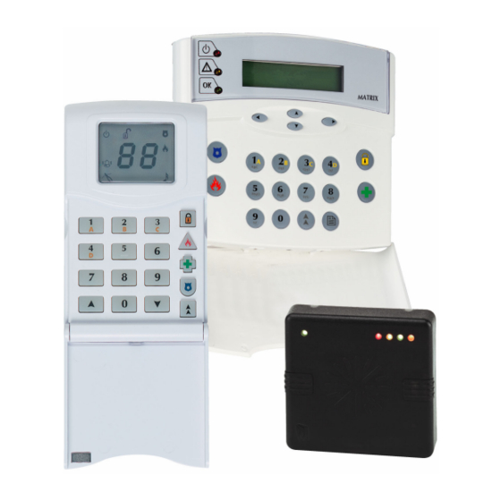
- Page 1 Matrix Installation Guide This Guide Supports the Following Panels: MATRIX 832 MATRIX 832+ MATRIX 424 RINS428-5 Tel: +44(0) 1709 700100...
- Page 2 Pyronix Association of Security Specialists Installer Support The Pyronix Association of Security specialists has been developed with the focus on what you the installer would like to see from one of the leading manufactures of security equipment. The philosophy behind the association is that you will receive tangible benefits, which are applicable to both the work and home environment.
-
Page 3: Table Of Contents
Matrix 832 / 832+ / 424 Contents SECTION 1: TECHNICAL SPECIFICATIONS & SYSTEM OVERVIEW ......1 1.1 Technical Specifications......................1 1.1.1 Main Control Panel..........................1 1.1.2 Additional Expanders ........................3 1.2 Battery Capacity Calculations....................4 1.2.1 UK Requirements..........................4 1.2.2 Norwegian & Danish Requirements....................4 1.2.3 Swedish Requirements ........................4 1.3 System Overview........................ - Page 4 Matrix 832 / 832+ / 424 7.5 Entering / Exiting Engineer Mode ..................32 7.5.1 Entering Engineer Mode......................... 32 7.5.2 Exiting Engineer Mode ........................32 7.5.3 Changing Engineer Code ....................... 32 7.6 Global System Options ......................33 7.6.1 System Options 1 ........................... 39 7.6.2 System Options 2 ...........................
- Page 5 Matrix 832 / 832+ / 424 8.1.9 Telephone Number 2 Allocation......................78 8.1.10 Telephone Number 3 Allocation....................79 8.1.11 Test Dial Sequence (Group Reporting)..................79 8.1.12 Anti-Code Algorithm Number ......................79 8.2 Reporting Formats ....................... 79 8.2.1 Telephone Number Programming & Format Allocation ..............82 8.2.2 BSIA Format Channel Map ......................83 8.3 Send Options &...
- Page 6 Matrix 832 / 832+ / 424 11.5 Modem Settings ........................111 11.5.1 Modem Types..........................111 11.5.2 Configuring Communications Options..................111 11.5.3 Configuring Dial Options ......................112 11.5.4 Configuring Dial Back Options ....................113 11.5.5 Configuring Computer Network Options ..................114 11.5.6 Character Set Options........................ 115 11.5.7 Customer Map ..........................
-
Page 7: Section 1: Technical Specifications & System Overview
Matrix 832 / 832+ / 424 Section 1: Technical Specifications & System Overview 1.1 Technical Specifications 1.1.1 Main Control Panel Matrix 832+ Matrix 832 Matrix 424 ZONES 0.54mA - Max 0.54mA - Max 0.54mA - Max Zone Loop Current Activation Resistance Zone DEOL Short circuit... - Page 8 Matrix 832 / 832+ / 424 Matrix 832+ Matrix 832 Matrix 424 FUSES Bell fuse Quick blow 1A – F1L Quick blow 1A – F1L Quick blow 1A – F1L Aux fuse Quick blow 1A – F1L Quick blow 1A – F1L Keypad fuse Quick blow 1A –...
-
Page 9: Additional Expanders
Matrix 832 / 832+ / 424 1.1.2 Additional Expanders PROGRAMMABLE OUTPUT EXPANDERS TRANSISTOR MX-ROX8T Supply Voltage 13.8V typical (9-16V range) Supply Current 45mA +/- 5 % @13.8V Outputs Type Open Collector Maximum Switching Voltage 12Vdc Maximum Switching Current 225mA RELAY MX-ROX8R Supply Voltage 13.8V typical (9-16V range) Supply Current... -
Page 10: Battery Capacity Calculations
Matrix 832 / 832+ / 424 1.2 Battery Capacity Calculations Maximum Battery recharge time must not exceed 72 hours to satisfy EN50131-6. 1.2.1 UK Requirements In the event of mains failure BS4737 Part 1, Section 7.2.1, specifies that a stand-by battery should be able to power the system for a non-alarmed period of 8 hours. -
Page 11: System Overview
Matrix 832 / 832+ / 424 1.3 System Overview Matrix 832 / 832+ Matrix 424 ZONES Zones on Main Board 8 fully programmable zones (16 4 fully programmable zones (8 using using zone doubling option) zone doubling) Zone Expander (On Board) 8 fully programmable zones on local 8 fully programmable zones on local plug In expander... - Page 12 Matrix 832 / 832+ / 424 Matrix 832 / 832+ Matrix 424 PGM Options 1. Off 1. Off 2. PIR remote LED enable (E-) 2. PIR remote LED enable (E-) 3. PIR Latch memory (C+) 3. PIR Latch memory (C+) 4.
- Page 13 9. Limited number of uses CENTRAL MONITORING OPTIONS Telephone Numbers 9 telephone numbers shared with 9 telephone numbers shared with pager, Pyronix PC format and digital pager, Pyronix PC format and digital communication formats communication formats Communication Protocols 1. Contact ID 1.
- Page 14 6.75kV/125Amps 6.75kV/125Amps OTHER 1. UDL programming software 1. UDL programming software Software Support 2. Pyronix MX-MON software to be 2. Pyronix MX-MON software to be used with: used with: a. Modem + Pyronix format a. Modem + Pyronix format b. RC12/RC112 + b.
-
Page 15: Section 2: Safety & Approvals
Matrix 832 / 832+ / 424 Section 2: Safety & Approvals SAFETY A technically competent person must carry out the mains installation in accordance with the national and local electrical installation regulations Protective Earth: This equipment must be earthed/grounded Functional Earth: Must be connected to earth terminal to allow the equipment to operate correctly. Has no safety implications. - Page 16 Matrix 832 / 832+ / 424 Page 10 RINS428-5...
- Page 17 Matrix 832 / 832+ / 424 RINS428-5 Page 11...
- Page 18 Matrix 832 / 832+ / 424 The maximum voltage applied to the equipment must not exceed the safety extra low voltage SELV limits specified in IEC60950 / EN60950 / UL60950 30VDC / 30VAC / 42.4Vpeak If you need to switch greater voltage, current or power you will require the use of a separate external switching relay Page 12 RINS428-5...
- Page 19 Matrix 832 / 832+ / 424 PYRONIX Ltd Pyronix House Braithwell Way Hellaby, Rotherham South Yorkshire S66 8QY ENGLAND, UK ://www.pyronix.com HTTP ______________________________________________________________ EU Declaration of Conformity EN45014 Manufacturer: As above Details of electrical equipment Model name(s) Matrix 832+ (Plastic & Metal Housing)
-
Page 20: Section 3: Mounting Procedure
Matrix 832 / 832+ / 424 Section 3: Mounting Procedure 3.1 Mounting Procedure for Matrix – Plastic & Metal Case The following steps illustrate basic mounting procedure for matrix plastic & metal case. (See section 12 for complete wiring diagrams) Step 1 - Remove the case lid from the matrix panel and check all parts and components are in place. -
Page 21: Panel Layout - Metal Case
Matrix 832 / 832+ / 424 3.3 Panel Layout – Metal Case Wall Fixin g Ho les Tamper Switch B atter y Te st Module (O ptional ) Tran sformer MX-Voice Mo dule Ba ttery 7 Ah - 17Ah Tamper Switch Wall Fixin g Ho le Wall Fixin g Ho le 3.4 Battery Installation Procedure... -
Page 22: Section 4: Cabling Rules For The Matrix Bus
Care must be taken when connecting devices to the bus over long cable runs. This is to ensure maximum system integrity under all circumstances (battery backup etc.). Pyronix recommends using standard 0.22mm cross sectional area, unshielded multi-core alarm cable for Matrix installations. -
Page 23: System Examples
Matrix 832 / 832+ / 424 4.1 System Examples A Matrix System is required to provide the following: 6 PIR Detectors (15mA each). A bell-box (max. current draw 400mA) connected to PGM1. 2 Matrix ICON Keypads (60mA each), one 50m away, and the other 100m away. A Matrix Transistor Output Expander (30mA) with 3 LEDs (10mA each) and 3 buzzers (12mA each) controlled by the outputs (accompanying the keypad 100m away) power supply. - Page 24 Matrix 832 / 832+ / 424 Example 2 This is now an acceptable solution because the ground return is shared between 2 cores of cable. Referring to table 2, the second column shows that by doubling up the ground return it is acceptable to have up to 4 ‘KEN’...
-
Page 25: Section 5: Operating Modes
Matrix 832 / 832+ / 424 Section 5: Operating Modes 5.1 Disarmed Mode This is the state of the panel when disarmed. However, Fire, Personal Attack, Medical, Tamper and 24 Hr inputs remain active 24 hours a day. 5.2 Armed Mode When the panel is armed an activation of any Access, Immediate or 24 hour zone will cause an alarm condition. -
Page 26: First To Alarm Mode
Matrix 832 / 832+ / 424 5.7 First to Alarm Mode When the system is in alarm mode it resets either automatically or by entering a valid user code. When the system is reset entering the user code the first zone to alarm will be displayed on the display. One further user code entry will clear the FTA and reset the panel to disarmed mode. -
Page 27: Section 6: Keypad/Reader Symbols & Indications
Matrix 832 / 832+ / 424 Section 6: Keypad/Reader Symbols & Indications 6.1 The ICON Keypad Rest of the World Denmark, Norway, Finland & Sweden Illuminated Correct AC & DC power sources AC power is OK Blinking Indicates DC source (battery) fault Indicates an AC fault Extinguished Indicates AC fault / no power to panel... -
Page 28: The Lcd Keypad
Matrix 832 / 832+ / 424 6.2 The LCD Keypad Rest of the World Denmark, Norway, Finland & Sweden Illuminated Correct AC & DC power sources AC power is OK Blinking Indicates DC source (battery) fault Indicates an AC fault Extinguished Indicates AC fault / no power to panel No power to the panel... -
Page 29: Section 7: Programming The System
Examples of both the PC software and ICON/LCD keypad functionality are shown with explanations of all the programming options (PC software can be downloaded from the Pyronix web site at www.pyronix.com). The following key is used in each of the programming sections to show the following functionality. -
Page 30: Addressing The Proximity Reader
Matrix 832 / 832+ / 424 7.2 Addressing the Proximity Reader The Matrix panel recognizes individual MX PROX readers by the link settings on the back of each MX PROX reader. NOTE: Before you start programming the system, use engineers function 754 to scan for all devices on the Matrix bus. -
Page 31: Finding Bus Devices
Matrix 832 / 832+ / 424 7.3 Finding Bus Devices Every time you add or remove a device on system bus, you must rescan for bus devices, so that the panel can recognise the new hardware. See page 99 for more details. LH Digit –... -
Page 32: Zone Types, Zone Attributes & Zone Settings
Matrix 832 / 832+ / 424 Zone Types Default Notes Zones Normally Closed Zone Doubling Disabled Fast Zones Disabled Zone 1 Fast Zone Disabled Zone Attributes Default Notes Chime Disabled Test Disabled Mask Disabled Double Knock Disabled Normally Open Disabled 7.4.3 Zone Types, Zone Attributes &... -
Page 33: User Codes, User Code Attributes & Proximity Card Allocation
Matrix 832 / 832+ / 424 7.4.4 User Codes, User Code Attributes & Proximity Card Allocation User Code Attributes User Code 01 User Codes 02 – 32 Notes Uses of Code Unlimited Unlimited Master User Enabled - 1234 Disabled - XXXXXX Omit (Bypass) Zones Enabled Enabled... -
Page 34: System Timers
Matrix 832 / 832+ / 424 7.4.9 System Timers Partition 1, 2, 3, 4 Timers Default Notes Bell Time 4 Minutes Entry Time 20 Seconds Exit Time 20 Seconds Bell Delay Time 0 Minutes Final Exit Delay Time 7 Seconds Inactivity Auto-Arm Disabled Number of Rearms... -
Page 35: Digital Communicator
Matrix 832 / 832+ / 424 7.4.11 Digital Communicator Partition Account Code Notes XXXX XXXX XXXX XXXX Up/Down Loading Code Notes 1234 Test Dials Default Notes Test Dial Time Disabled Test Dial Interval Disabled Group Reporting Send to Tel 1 with Tel 2 as a backup Telephone 1 Disabled Telephone 2... -
Page 36: Dd243 Option Defaults
Matrix 832 / 832+ / 424 7.4.14 DD243 Option Defaults Option Default Notes Enable DD243 Option 2-8 Open Set Zone Stops Confirmation Open Entry Zone Stops Confirmation Omit Open Zones on Confirmation Timer End Cut Wires Stops Causes Confirmed Alarm Fire, PA and Medical Keys Disabled Entry Time End 7.4.15 Confirmation Timer Defaults... -
Page 37: Zone Mapping Defaults
Matrix 832 / 832+ / 424 7.4.16 Zone Mapping Defaults Zone Zone Map Notes Map-1 Map-2 Map-3 Map-4 Map-5 Map-6 Map-7 Map-8 Map-9 Map-10 Map-11 Map-12 Map-13 Map-14 Map-15 Map-16 Map-17 Map-18 Map-19 Map-20 Map-21 Map-22 Map-23 Map-24 Map-25 Map-26 Map-27 Map-28 Map-29... -
Page 38: Entering / Exiting Engineer Mode
Matrix 832 / 832+ / 424 7.5 Entering / Exiting Engineer Mode Engineer Mode must be used to program and change the functionality of the matrix panel. This includes changing the engineer code, programming zones, partitions etc. Whilst in Engineer Mode all tamper alarms (including the case tamper), will be suppressed. -
Page 39: Global System Options
Matrix 832 / 832+ / 424 7.6 Global System Options PC Programming Procedure The PC window illustrated below shows how to program the global system options from the PC software. Once an option has been chosen, press <save> and proceed to the next window. NOTE: To select different system options, click the drop-down menu for System Options 1, 2 or 3. - Page 40 Matrix 832 / 832+ / 424 Log and Event Reporting Yes - This option allows the engineer to limit the event log entry and report to the Central Monitoring Station to a total of 16 events in a row for any one event. No - This option allows the engineer to set the event log entry and report to the Central Monitoring Station for unlimited number of events.
- Page 41 Matrix 832 / 832+ / 424 System Options 2 Bus Device Missing The system scans the system bus for all installed components (keypads, proximity readers, zone/output expanders). Tamper Alarm - If a component is missing from the panel, a tamper alarm will be created and a system fault condition will be generated and displayed on the keypad.
- Page 42 Matrix 832 / 832+ / 424 Suspend Exit Timer On Open Zone Yes - The exit timer will suspend during arming, if any zones are open. The panel will arm only when all zones are closed. No - The exit timer will not be suspended if any zones are left open. At the end of the exit time the panel will go into an alarm condition.
- Page 43 Matrix 832 / 832+ / 424 System Options 3 Hide Display After 20 Seconds Of Inactivity - Hide display after 20 seconds of keypad inactivity. Never - Do not hide display. Hidden Display Mode The Matrix alarm panel incorporates a hidden display (confidential mode) feature, that can be enabled / disabled by your installation engineer.
- Page 44 Matrix 832 / 832+ / 424 NOTE: When in User Menu mode (and hidden display mode is enabled), the keypad will drop out of the user menu and then into hidden display mode if no keys are pressed for 20 seconds. As long as a key is pressed at least once every 20 seconds then user mode will remain active.
-
Page 45: System Options 1
Matrix 832 / 832+ / 424 SU PPLY FA U L T A RMED A L A R M FIRE R EAD Y P.A. D A Y T A MPE R P .A. FIR E FUN C Keypad Programming Procedure 7.6.1 System Options 1 >... -
Page 46: Zone Types, Configuration, Attributes & Partition Allocation
Matrix 832 / 832+ / 424 7.7 Zone Types, Configuration, Attributes & Partition Allocation PC Programming Procedure The PC window below shows how to program zone types, arm modes, zone partition allocation and zone attributes from the UDL software. Once an option has been chosen, press <save> and proceed to the next window. - Page 47 Matrix 832 / 832+ / 424 NOTE: When zone doubling is enabled the matrix panel must be powered down and then powered up before the change will take place. If zone doubling is used only one detector per zone may be used. Table 1 –...
- Page 48 Matrix 832 / 832+ / 424 Arm Modes and Partitions The system can be divided into up to 4 independent subsystems. One zone can be allocated to one subsystem. Within each subsystem the zones can be operated in 4 different Arm Modes configurations A, B, C and D.
- Page 49 Matrix 832 / 832+ / 424 It is possible by using this type of zone to arm / disarm the system in any arm mode Momentary by using an external pulsed switch. Keyswitch Arm Zones and DD243 If the option ‘Open set zone stops confirmation’ is on, this zone can be used to satisfy sections 6.3b and 6.4.3 of DD243 when connected to a shunt lock.
-
Page 50: Zone Types
Matrix 832 / 832+ / 424 FA U L T A RMED A L A R M SU PPLY FIRE D A Y R EAD Y P.A. T A MPE R P .A. FIR E FUN C Keypad Programming Procedure 7.7.1 Zone Types >... - Page 51 Matrix 832 / 832+ / 424 Enter followed by zone number from [01 - 32]. The zone type for Arm A will then be displayed > buttons to choose a zone type. Press to accept and save the new zone type. The zone type for Arm B will then be displayed >...
- Page 52 Matrix 832 / 832+ / 424 The attributes for Arm B will now be displayed > To select an option use the buttons. To change an option press the button. To save the changes press . An acceptance tone will be played. Option Option Off = Alarm LED Off Option On = Alarm LED On...
-
Page 53: Zone Names Programming From Lcd Keypad
Matrix 832 / 832+ / 424 Screens displayed through zone programming sequence: function MATRIX Zone numbers: Enter the zone number [01 – 32] and press B to continue. ARM MODE entry / exit MATRIX Zone configurations: Use the >? keys to scroll through zone types. Press B and repeat 4 times for part sets A, B, C and D. -
Page 54: Key Map Tables
Matrix 832 / 832+ / 424 7.7.4 Key Map Tables The following tables show how to obtain certain characters when programming user names, zone names etc. Each time you press the same numerical key, the next character is chosen. There are three tables shown. Use only the table that corresponds to the country of installation as some keys will vary. -
Page 55: User Codes & User Attributes
Matrix 832 / 832+ / 424 7.8 User Codes & User Attributes PC Programming Procedure The PC window below shows how to program user codes and names, engineer codes, engineer names and user attributes from the PC software. Once you have chosen an option press <save> and proceed to the next window. - Page 56 Matrix 832 / 832+ / 424 MEANING Programmable Options Explanation User Code Types Limited user code - This code allows the user to arm / disarm the system, duress arming / disarming, omit (bypass) zones if allowed by the engineer, Fire / PA / Medical keypad alarm activation, display open zones if allowed by the engineer, silence fault tones, view event log, change volume, change brightness.
- Page 57 Matrix 832 / 832+ / 424 User Code Active in Partitions The selected user code may be active in partitions 1,2,3 or 4 by ticking the appropriate box. NOTE: If one common keypad is used and different user codes are allocated to 4 separate partitions, for instance partition 1 is allocated to flat 1, partition 2 is allocated to flat 2, partition 3 is allocated to flat 3 and partition 4 is allocated to flat 4, then if user one from partition 1 chooses code 1234 and user 1 from partition 2 chooses the same code they will be able to arm / disarm both flats.
-
Page 58: Programming User Codes
Matrix 832 / 832+ / 424 SU PPLY FA U L T A RMED A L A R M FIRE R EAD Y P.A. D A Y T A MPE R P .A. FIR E FUN C Keypad Programming Procedure 7.8.1 Programming User Codes The engineer should only program the user codes attributes. -
Page 59: Keypads & Proximity Readers Partition Allocation
Matrix 832 / 832+ / 424 7.9 Keypads & Proximity Readers Partition Allocation PC Programming Procedure The PC window below shows how to assign a keypad to a partition from the PC software. Once an option has been chosen press the <save> button and proceed to the next window. NOTE: Each keypad &... - Page 60 Matrix 832 / 832+ / 424 Armed Message This message can be programmed by the installer to display text on the LCD display while the control panel is in armed mode, and the keypad is configured as a private keypad. It is possible to choose a message to be displayed from “LCD Keypad Text 1”.
-
Page 61: Icon Keypad Programming
Matrix 832 / 832+ / 424 SU PPLY FA U L T A RMED A L A R M FIRE R EAD Y P.A. D A Y T A MPE R P .A. FIR E FUN C Keypad Programming Procedure 7.9.1 Icon Keypad Programming 7.9.1.3 Icon Keypad Partition Allocation Enter... - Page 62 Matrix 832 / 832+ / 424 7.9.2.3 Change Label Messages on LCD keypad NOTE: This option allows the engineer to edit and change the text on all available label messages. There are 32 (01 – 32) different labels that can be selected. The engineer can edit any of these labels. BUWV.
- Page 63 Matrix 832 / 832+ / 424 The default Day message is displayed when the panel is disarmed in day mode. It is displayed on the bottom line of the LCD display. The default Armed message is displayed when the panel is Armed and has been programmed for private mode.
-
Page 64: Proximity Reader Programming
Matrix 832 / 832+ / 424 7.9.2.6 Setting the Contrast of the LCD Display BUWY. Enter The following display will be shown. Adjust contrast Use up - down keys MATRIX key reduces the contrast key increases the contrast Press to accept the new contrast setting. The LCD contrast controls the darkness of the characters shown on the LCD display. -
Page 65: System Faults & Tamper Alarms Warning Allocation
Matrix 832 / 832+ / 424 7.10 System Faults & Tamper Alarms Warning Allocation PC Programming Procedure The PC window below shows how to assign system faults and tamper alarms to a partition from the PC software. Once an option has been chosen, press <save> and proceed to the next window. MEANING Programmable Options Explanation Active in Partition... -
Page 66: Partition Options
Matrix 832 / 832+ / 424 7.11 Partition Options PC Programming Procedure The PC window below shows partition options 1 and 2 for partition 1 of the PC software. On the left hand side of this screen shot is a partition selection box, which should be used to change between desired partitions. 1, 2, 3 and 4. - Page 67 Matrix 832 / 832+ / 424 Display Open Zones When Disarmed Yes - When the panel is in disarmed mode, any open zones will be displayed on the keypad. To arm the system all zones should be closed. If all zones are closed the ready LED will be activated on the keypad and only then the system should be armed.
-
Page 68: Partition Options 1
Matrix 832 / 832+ / 424 External Sounder Normal Operation - The sounders will operate using the standard bell time and re-arm settings. French Operation - The resulting bell output (type 14) operation is as follows: The Bell time is fixed to 3 minutes (or seconds if bell time in seconds is selected). No more than 4 bell activations are allowed per arm period. -
Page 69: Partition Options 2
Matrix 832 / 832+ / 424 7.11.2 Partition Options 2 Enter followed by one digit for the desired partition number [1 - 4]. To choose an option use the > buttons. To change an option setting, press the button. To save the changes press . - Page 70 Matrix 832 / 832+ / 424 MEANING Programmable Options Explanation Arm Modes There are 4 arm modes that can be programmed to arm different zones within one partition area. Example Partition 1 Partition 2 Partition 3 Partition 4 Arm A Arm A Arm A Arm A...
-
Page 71: Exit Terminator Type For Arm Mode A
Matrix 832 / 832+ / 424 Common Partition Programming Auto Arm Partition When These Partitions Arm (Partition Dependency) In some instances there is a need to program one or more partitions as common partitions. For instance if we use partition 2, 3 and 4 to protect 3 separate flats we might need to use partition 1 as a common partition protecting the lobby area. -
Page 72: Exit Terminator Type For Arm Mode C
Matrix 832 / 832+ / 424 7.12.3 Exit Terminator Type for Arm Mode C BVWT Enter followed by one digit for the desired partition number [1 - 4]. The current Arm type will be displayed. To select the type of arm mode enter [00], [01] or [02]. To save the changes press . -
Page 73: Keyswitch Zone Arm Mode Allocation
Matrix 832 / 832+ / 424 7.12.7 Keyswitch Zone Arm Mode Allocation BVWX Enter followed by one digit for the desired partition number from [1 - 4]. The current Arm mode will be displayed. To choose an option, enter [01]…[04]. To save the changes press . -
Page 74: System Timers
Matrix 832 / 832+ / 424 7.13 System Timers PC Programming Procedure The PC window below shows how to program the system times from the PC software. On the left hand side of this screen shot is a partition selection box, which should be used to change between desired partitions. 1, 2, 3 and 4. - Page 75 Matrix 832 / 832+ / 424 Auto Arm Commencing Time Every Day - The system can be programmed to auto-arm every day at preprogrammed time (0000 = No Auto Arm timer). Example: If the time programmed is 15’00 the arming procedure will follow in 4 different stages during 30 min before the system actually arms.
-
Page 76: Bell Time
Matrix 832 / 832+ / 424 SU PPLY FA U L T A RMED A L A R M FIRE R EAD Y P.A. D A Y T A MPE R P .A. FIR E FUN C Keypad Programming Procedure 7.13.1 Bell Time Enter followed by the one digit for the desired partition number from [1 - 4]. -
Page 77: Programmable Outputs
When the system in walk test mode this output will emit 0V that will enable the LED. On exiting the walk test mode the LED will be disabled. This option will only work if the detectors have a remote LED enable facility (e.g. Pyronix Enforcer Super, Octopus Super, Equinox AM). [02] = C+ (Latch) This feature is used to reset the latch option of detectors that have this function. - Page 78 Matrix 832 / 832+ / 424 [04] = Follow Arm / Disarm By using this option the programmable output will change state as the panel is armed and disarmed. This may be used for example to electronically lock a door when the panel is armed and unlock it when the panel is disarmed, or with radio-transmitters, etc.
- Page 79 Matrix 832 / 832+ / 424 Digital Communicator Outputs Output types 18 to 25 are controlled by the on board digital communicator and follow the operation of the BSIA fast format protocol channels, these outputs would generally be used for example in conjunction with an external digital communicator.
-
Page 80: Pgm Programming
Matrix 832 / 832+ / 424 SU PPLY FA U L T A RMED A L A R M FIRE R EAD Y P.A. D A Y T A MPE R P .A. FIR E FUN C Keypad Programming Procedure 7.14.1 PGM Programming Enter . -
Page 81: Section 8: Communication Programming
Matrix 832 / 832+ / 424 Section 8: Communication Programming The Matrix 832 & 424 are integrated with a digital communicator. Using internationally recognised formats, the Digi Com will allow the panel to communicate with Central Monitoring Stations and different service companies. -
Page 82: Digital Communicator
Anti-code Algorithm Number - This is a 1-digit number (from 0 to 8) that tells the panel which algorithm to use to generate the seed code. NOTE: Most Pyronix Anti-code generating software will only generate codes for Algorithm 0. Number of Voice Messages – This is the number of times a voice message is dialled for each telephone number. - Page 83 Matrix 832 / 832+ / 424 Test Dial Interval - This may be programmed in days, hours or minutes depending on the Central Monitoring Station policy. If the interval is [00], the time becomes the amount of hours and minutes between each test call (e.g.
-
Page 84: Account Codes & Account Partition Allocation
Matrix 832 / 832+ / 424 SU PPLY FA U L T A RMED A L A R M FIRE R EAD Y P.A. D A Y T A MPE R P .A. FIR E FUN C Keypad Programming Procedure 8.1.2 Account Codes &... -
Page 85: Telephone Number 3 Allocation
[. The current code will be displayed. Press 1 digit for the code from [0 – 8], and press B to accept the changes. An acceptance tone will be heard. NOTE: Most Pyronix Anti-code generating software will only generate codes for Algorithm 0. 8.2 Reporting Formats... - Page 86 Matrix 832 / 832+ / 424 MEANING Programmable Options Explanation Telephone numbers Up to 9 telephone numbers may be programmed with a total length up to 32 digits. Use a comma ( , ) to denote a 2 second pause. Reporting Formats Contact ID - This is a standard events reporting format, the event numbers of which are pre-programmed automatically.
- Page 87 = 1. Sensor no 2. User no 3. Set level (arm mode) Pyronix PC Format – This format is designed to allow the panel to report the same codes as per Contact ID instead to a Digital Receiver to a PC by using the Pyronix Maintenance & Monitoring software and std. US Robotics modem supplied by Pyronix.
-
Page 88: Telephone Number Programming & Format Allocation
The reporting format for this number will now be displayed Press [0] to choose Contact ID format, [1] to choose BSIA Fast format, [2] to choose Pyronix Format, [3] to choose Pager Format, or [4] to choose Voice Module Format. -
Page 89: Bsia Format Channel Map
Matrix 832 / 832+ / 424 8.2.2 BSIA Format Channel Map BXWW Enter . The current channel map will be displayed. Enter 8 digits from [1 - 8]. An acceptance tone will be heard after the 8 digit has been pressed. All the digits must be different or operation of the BSIA channels will be unpredictable. - Page 90 Matrix 832 / 832+ / 424 Arm B - When the panel is armed in Arm B mode the engineer can choose which events to report to the central monitoring station from Alarms, PA alarms, Fire alarms, Maintenance information, Open / Close, Medical, Confirmed Alarms and omitted (bypassed) zones information.
-
Page 91: Disarmed Mode Events Send Options
Matrix 832 / 832+ / 424 Activation When an event occurs the MX-VOICE transmits the related voice message to the alarm event. SU PPLY FA U L T A RMED A L A R M FIRE D A Y R EAD Y P.A. -
Page 92: Arm Mode C Events Send Options
Matrix 832 / 832+ / 424 8.3.4 Arm Mode C Events Send Options Enter followed by one digit for the desired partition number from [1 - 4]. To choose an option use > buttons. To change an option setting, press the button. -
Page 93: Allocating Telephone Numbers To Alarm Types In Partitions
Matrix 832 / 832+ / 424 8.3.7 Allocating Telephone Numbers to Alarm Types in Partitions Enter followed by one digit for the desired partition number from [1 - 4]. Enter the alarm type from [1 - 6]*. [1]* =Alarm, [4]* =Maintenance, [7]* =Confirmed, [2]* =PA, [5]* =Open/Close... -
Page 94: Section 9: Installing Dd243
Installing the Matrix Panel to DD243 The Pyronix Matrix Panel has been carefully designed to incorporate the latest DD243: 2002 features. There are several ways the Matrix can be programmed and installed to satisfy the DD243 requirements. Each of the basic methods is outlined below, variations of these methods exist and it is left to the individual installer to tailor the programming to fit the exact requirements of the installation. -
Page 95: Resetting Following An Alarm Condition
Matrix 832 / 832+ / 424 Installing a Matrix with Proximity Readers Pyronix Proximity Readers are available which directly connect to the Matrix Keypad Bus. This installation method satisfies DD243 section 6.3d – ‘Portable ACE’ and DD243 section 6.4.4 - ‘Completion of unsetting is achieved using portable ACE’. -
Page 96: Dd243 Options Table
Matrix 832 / 832+ / 424 9.6 DD243 Options Table The table below summarizes the expected settings for each method of installation to comply with DD243. Means of Unsetting DD243 Settings Arm Zone Operation Entry Zone Operation Entry Time End Unlocking the Initial Entry Normal Normal... - Page 97 Matrix 832 / 832+ / 424 MEANING DD243 Options Enable DD243 Options This is the first option in the DD243 section. This option needs to be enabled before any of the remaining options will be considered. Change this option to [Yes] to allow the remaining DD243 features to be used. The factory default setting is [No].
-
Page 98: Dd243 Options 1
Matrix 832 / 832+ / 424 9.7 DD243 Options 1 > Enter . Use the keys to select an option to change. To change the state of the option, press the key once. Repeated pressing of the key toggles the state. Option Off / LED Off On / LED On... -
Page 99: Section 10: Events Memory Log & System Maintenance
Matrix 832 / 832+ / 424 Section 10: Events Memory Log & System Maintenance The Matrix 832, 832+ & 424 control panels have an event memory log of 300 events. These are displayed with time and date and can be read from both LCD and Icon keypads or using the UDL software from a PC. 10.1 Reading The Event Log PC Programming Procedure Downloading the Log from the Panel... -
Page 100: Viewing Event Log Memory
Matrix 832 / 832+ / 424 MEANING Programmable Options Explanation Last – This option enables the last log to be down loaded Previous 1, Previous 2, Previous 3 – This shows the previous 3 logs downloaded Complete History – This shows all events downloaded using the <new events> Download option. Partitions To View –... - Page 101 Matrix 832 / 832+ / 424 ICON Keypad Interpretation Event Log Table Keypress Icon Description 00 - 32 BELL Entry / Exit timer expired. The number refers to the zone. 00 - 32 PA (flash) PA zone activated, number signifies zone (00 = keypad) 00 - 32 FIRE (flash) FIRE zone activated, number signifies zone (00 = keypad)
- Page 102 Matrix 832 / 832+ / 424 Keypress Icon Display Description Open / Close 01 - 32 Armed in mode A by user, number signifies code used 01 - 32 Armed in mode B by user, number signifies code used 01 - 32 Armed in mode C by user, number signifies code used 01 - 32 Armed in mode D by user, number signifies code used...
- Page 103 Matrix 832 / 832+ / 424 LCD Keypad Interpretation Event Log Table Press E Description Entry Top Line Bottom Line Entry Exit Zone number Entry / Exit timer expired. The number refers to the zone. Personal Attack Zone number PA zone activated, number signifies zone (00 = keypad) Fire Alarm Zone number FIRE zone activated, number signifies zone (00 = keypad)
- Page 104 Matrix 832 / 832+ / 424 Press E Description Entry Top Line Bottom Line System Events Engineer end Bell time expired Engineer start Engineer Mode entered Walk test enter Walk test entered Walk test end Walk test exited Log cleared Log cleared NVM reset NVM reset to factory defaults...
-
Page 105: System Faults & Maintenance
Matrix 832 / 832+ / 424 10.2 System Faults & Maintenance MEANING Programmable Options Explanation NOTE: See system faults in the memory log table in Section 10.1 for descriptions of possible faults, which may occur. 10.2.1 NVM Reset to Factory Default The system may be programmed for two different ways of reset to factory default. -
Page 106: Local Up / Down Loading Session (Rs232)
Matrix 832 / 832+ / 424 10.2.5 Local Up / Down Loading Session (RS232) Local up/downloading can take place via the on-board RS232 port. In order for the panel to see the local PC this function must be started. The panel busy display will be shown on the keypad while the PC is connected to the panel and the devices on the KD line will become totally unusable, this includes all outputs and keypads. -
Page 107: Section 11: Udl Pc Software Data Management
Matrix 832 / 832+ / 424 Section 11: UDL PC Software Data Management This section shows how to create groups, customer details and default records from PC software. Dial options and configuration are also shown in detail. 11.1 Customer Explorer After entering your name and password to enter the P.C. - Page 108 Matrix 832 / 832+ / 424 Customers On the right hand side of the screen the customers for the selected group are shown. The toolbar at the top of the screen provides the following functions: Add a new customer. Edit the currently highlighted customer and will open the customer edit window. Delete the currently highlighted customer.
-
Page 109: Editing Customer Information
Matrix 832 / 832+ / 424 11.2 Editing Customer Information Enter the customer details using this window. The toolbar at the top of the screen provides the following functions: Close window. If changes to the customer have been made since the last save then a prompt is shown to warn that the details need saving. -
Page 110: Global Information
Matrix 832 / 832+ / 424 11.2.1 Global Information Enter details about the customer’s control panel. Your Reference No. This is a unique code for the customer. This is only entered when adding a customer, once saved this cannot change. Panel Type This is a list of available panel types. -
Page 111: Exporting And Importing Customers
Press OK to create the backup. The file that is created is called the same as the Customer Reference number. For example, if the Customer Reference is “20” then the database created will be called “44.mdb” and is stored in the directory “C:\Program Files\Pyronix UDL Software”. Customers are imported from the Customer Explorer screen. -
Page 112: Entering Panel Details & Uploading/Downloading To The Panel
Matrix 832 / 832+ / 424 11.4 Entering Panel Details & Uploading/Downloading to the Panel From the Customer Details screen click on to edit the panel programming data. The panel details screen is split into separate screens or tabs. The drop down list showing V2.2 in the above screenshot is the panel version. -
Page 113: Default Records
Matrix 832 / 832+ / 424 Instruct a panel to dial you back. This is only available when connected to a panel. See section 12.4.5 for more information. Get data from a panel. This is only available when connected to a panel. See section 12.4.7 for more information. -
Page 114: Normal Dial To The Panel
Matrix 832 / 832+ / 424 To create more Default Records or Templates, press the New button or select the option Default Record on the main menu as shown below. 11.4.2 Normal Dial to the Panel To perform a normal dial to the panel press this icon. Before performing this operation the Master User needs to enter TZ on a keypad connected to Panel to allow the digital modem to detect ringing from the PC. -
Page 115: Local Connection
Whilst connected to the panel the operation of upload/download is that same as for connecting using a modem over a telephone line. To select the Com port to use, see section 11.5.1. The required cable is available from Pyronix. 11.4.5 Dial Back When connected to a panel the engineer can request that the panel disconnects the current upload/download session and dials a specified telephone number to start a new session. -
Page 116: Online Panel Information
Matrix 832 / 832+ / 424 11.4.9 12.4.9 Online Panel Information Shows maintenance information about the panel when connected. Shows the status of each partition, zones, devices and faults. Partition Information Shows information for each partition. Press the 1 to 4 buttons to get information on each partition. A Green circle shows which mode the panel is in apart from Alarm, which is shown as a Red circle. -
Page 117: Modem Settings
Another issue to consider is Software Modems, internal modems that use the PC's processor instead of their own processor. Pyronix has not carried out extensive testing on this type of modem, and our recommendation is that you replace the modem with a hardware modem. -
Page 118: Configuring Dial Options
Matrix 832 / 832+ / 424 ATS10=255 Compatible Modem - Most new modems do not allow the S10 register to be set to 255, see the modem manual for a description of what the S10 register does. If connection is being lost around 25 seconds after connecting to a panel unselect this option. -
Page 119: Configuring Dial Back Options
Matrix 832 / 832+ / 424 11.5.4 Configuring Dial Back Options Dial Back Number - This is the number that the panel will dial. Answer Tone Time - When the panel dials it will keep the answer tone going for this length of time, the value of this can be 1 to 51 seconds. -
Page 120: Configuring Computer Network Options
Matrix 832 / 832+ / 424 11.5.5 Configuring Computer Network Options This will allow the use another database stored in another directory or computer. This could be a directory on a network so that multiple PCs can share the same customer information. The steps to follow for creating a network version are: Create directory on Network - Using Windows Explorer create a directory on the network. -
Page 121: Character Set Options
Matrix 832 / 832+ / 424 11.5.6 Character Set Options This is used for displaying and editing LCD keypad text on the panel information screen. Selecting the correct Charset on this screen will allow the correct editing of this text for the Matrix LCD screen. Failure to set this correctly could result in incorrect data being sent to the panel. -
Page 122: Customer Map
Matrix 832 / 832+ / 424 11.5.7 Customer Map Select the paint package to use on the PC when creating panel maps. Any paint program can be used as long as it can save images in BMP or JPEG format. Page 116 RINS428-5... -
Page 123: Configuring Other Options
Matrix 832 / 832+ / 424 11.5.8 Configuring Other Options Print out panel details every time you save - Select this to get a print out of the panel details when saved. Auto save Details before a Data to Panel - This will save the panel details before the data is sent. If there is a problem with the data then the data is not sent. -
Page 124: Using Help
Matrix 832 / 832+ / 424 11.6 Using Help Access the help system from the Help menu on the main screen. The help system is divided into the following sections: Customer Information - Shows how to manage customers within the system. Panel Information - Shows how to upload/download and contains descriptions for each feature for all supported panels. -
Page 125: Section 12: Installation, Service & Maintenance
Matrix 832 / 832+ / 424 Section 12: Installation, Service & Maintenance Installation This section makes no attempt to detail how one should install an alarm panel. It does however provide some basic information relating to the Matrix alarm panel with regards to installation, service and maintenance. For details concerning mechanical panel installation and cable routing, please refer to sections 4 &... -
Page 126: Scanning For Devices
Matrix 832 / 832+ / 424 Telephone Line Monitoring It is advisable to periodically check that the alarm panel can still contact the CMS. The Matrix alarm panel provides a suitable function that allows the CMS to be test dialled periodically, see section 9. The panel also monitors the telephone line and will generate a system fault if the line is removed, however the presence of a line does not guarantee the ability to dial a CMS. - Page 127 Matrix 832 / 832+ / 424 Maintenance Log Date Notes Engineer Installation Details Installer Engineer CMS Tel. Telephone RINS428-5 Page 121...
- Page 128 Matrix 832 / 832+ / 424 Diagrams This section contains a number of wiring diagrams showing you how to connect to the Matrix alarm panel and the various bus devices. These drawings are intended to help speed up your installation time as well as provide you with real world connection solutions and ideas.
-
Page 129: Matrix 832 Pcb
Connection to Analogue PSTN telephone line Telephone direct connection Series connection of telephone line To be connected to remaining telephone line equipment within the installation RS232 Connection to computer serial port via a Pyronix RS232 cable (RCON095) RINS428-5 Page 123... -
Page 130: Matrix 832+ Pcb
Connection to Analogue PSTN telephone line Telephone direct connection Series connection to telephone line To be connected to remaining telephone line equipment within the installation RS232 Connection to computer serial port via a Pyronix RS232 cable (RCON095) Page 124 RINS428-5... -
Page 131: Matrix 424 Pcb
Matrix 832 / 832+ / 424 12.4 Matrix 424 PCB NOTE: The Matrix 424 does not have a Global Tamper (GT) terminal. To create a tamper loop, use the AUX– terminal and a spare zone programmed as ‘Tamper’. R S2 32 +BELL- KD Z1 +AUX- Z3... -
Page 132: Matrix Voice Module
Matrix 832 / 832+ / 424 12.5 Matrix Voice Module MATRIX ME SSA GE N UM BER 1 -8 PL AY / RE COR D MEANING + BAT- To program a voice message into the MX-VOICE without connecting it to a Matrix panel, connect a 9 -12V battery to the BAT terminals (Remove the battery before connecting the MX-VOICE to the Matrix alarm panel). -
Page 133: Voice Module Connections To Matrix 832
Matrix 832 / 832+ / 424 12.5.1 Voice Module Connections to Matrix 832+ MATRIX 17v A.C. Output Data & Power MX Voice module connections Connection to Matrix control panel Ribbon Cable Aux fuse 1Amp Bell Fuse 1Amp Keypad fuse 1 Amp +BELL- +AUX- P S T N... -
Page 134: Mx-Batt Battery Monitor Board
Matrix 832 / 832+ / 424 12.6 MX-BATT Battery Monitor Board BAT OUT 17V ~ Reset Button The battery monitor board is a unique monitoring and test board for the Matrix range of control panels, including the Matrix 832, 832+, 424 and Matrix 6. Connect the battery monitor board to the control panel as illustrated below. -
Page 135: Matrix Zone Expanders
Matrix 832 / 832+ / 424 12.7 Matrix Zone Expanders 12.7.1 Local Plug-On 8 Zone Expander The MX-16 expands the system by a further 8 DEOL zones (16 if zone doubling is used). NOTE: The Matrix 832/832+ cannot support more than 16 DEOL zones, and the Matrix 424 no more than 12, so if a local expander is fitted remote expanders will be ignored;... - Page 136 Matrix 832 / 832+ / 424 Matrix 832+ R1 R2 MX-VOICE +AUX- Aux fuse 1Amp Bell Fuse 1Amp Key pad fus e 1 A mp COMMON COMMON COMMON COMMON +AUX- Relays +A UX - +B ELL- Matrix 424 +AUX- COMMON COMMON COMMON COMMON...
-
Page 137: Mx-Rix With Zone Analyser
Matrix 832 / 832+ / 424 12.7.2 MX-RIX with Zone Analyser The MX-RIX expands the system by a further 8 DEOL zones (16 if zone doubling is used). NOTE: The Matrix 832/832+ cannot support more than 16 DEOL zones, and the Matrix 424 no more than 12, so if a local expander is fitted remote expanders will be ignored;... - Page 138 Matrix 832 / 832+ / 424 Operation When connected initiate scan for devices on the bus by entering BYWV. The MX-RIX with Zone Analyser input expander has been designed to enable sensitivity adjustment “de- bounce & pulse count switches” for shock sensors that are designed to detect sharp vibrations. When changing between on board and remote zone expanders on an already installed system, it is better to remove all the zone expanders, onboard or remote and perform a scan, then add the expander and perform another scan.
- Page 139 Matrix 832 / 832+ / 424 Example of how pulse count and debounce settings combine ALARM TRIP THRESHOLD Small Pulse Alarm Pulse Count 1 Pulse Count High Sensitivity Debounce Debounce ALARM TRIP THRESHOLD Small Pulse Alarm Pulse Count 1 Pulse Count Debounce Sensitivity Debounce...
- Page 140 Matrix 832 / 832+ / 424 MX-RIX with Zone Analyser Connection to Matrix 832 NVM Rese t Relay 17V~ +BAT- B+ B- BT GT NC C Z2 Z3 +AUX- Z6 Z7 LCD Key pad ICON Keypad NOTE: Matrix 424 connections are the same as those for Matrix 832. Page 134 RINS428-5...
- Page 141 Matrix 832 / 832+ / 424 MX-RIX with Zone Analyser Connection to Matrix 832+ Bell Fuse 1Amp Aux fuse 1Amp Ke yp ad fu se 1 A mp +BEL L- +AU X- LCD Keypad ICON Keypad RINS428-5 Page 135...
-
Page 142: Matrix Pgm Expanders
Matrix 832 / 832+ / 424 12.8 Matrix PGM Expanders RELAY RELAY RELAY RELAY RELAY RELAY RELAY RELAY MX-ROX8R NC = Normally Closed C = Common NO = Normally Open MX-ROX8T The ROX8R/8T is an additional feature to the Matrix panel, which will enable all 12 programmable outputs on the matrix panel to be used. -
Page 143: Mx-Rox8R/8T Connections To 832
Matrix 832 / 832+ / 424 12.8.1 MX-ROX8R/8T Connections to 832 NVM Reset Relay 17V~ +BAT- B+ B- BT GT NC C Z2 Z3 +AUX- Z6 Z7 LCD Keypad ICON Keypad NOTE: Matrix 424 connections are the same as those for Matrix 832. RINS428-5 Page 137... -
Page 144: Mx-Rox8R/8T Connections To 832
Matrix 832 / 832+ / 424 12.8.2 MX-ROX8R/8T Connections to 832+ Aux fuse 1Amp Bell Fuse 1Amp Keypad fuse 1 Amp +BELL- +AUX- LCD Keypad ICON Keypad Page 138 RINS428-5... -
Page 145: Keypads & Proximity Readers Connections
Matrix 832 / 832+ / 424 12.9 Keypads & Proximity Readers Connections NOTE: Terminal connections for the Matrix 424 are the same as for the Matrix 832, with the exception of KTR. This must be connected to a spare zone programmed as ‘Tamper’. NOTE: When connecting keypads to a Matrix panel, the first keypad must always be ID1. -
Page 146: Connecting A Single Keypad To Matrix 832
Matrix 832 / 832+ / 424 12.9.2 Connecting a Single Keypad to Matrix 832 + Aux fuse 1Amp Bell Fuse 1Amp Keypad fuse 1 Amp +BELL- +AUX- LCD Keypad 17V AC Output ICON Keypad Keypad RKP1 Page 140 RINS428-5... -
Page 147: Connecting Multiple Keypads To A Matrix 832 - Daisy Chain
Matrix 832 / 832+ / 424 12.9.3 Connecting Multiple Keypads to a Matrix 832 – Daisy Chain NVM Rese t Relay 17V~ +BAT- B+ B- BT GT NC C Z2 Z3 +AUX- Z6 Z7 RKP 1 LCD Ke ypa d KEYPAD ICO N Keypad Keypads wired in daisy chain... -
Page 148: Connecting Multiple Keypads To A Matrix 832 - Star Configuration
Matrix 832 / 832+ / 424 12.9.4 Connecting Multiple Keypads to a Matrix 832 – Star Configuration NVM Reset Relay 17V~ +BAT- B+ B- BT GT NC C Z2 Z3 +AUX- Z6 Z7 LCD Keypad ICON Keypad Keypads wired in star configuration. -
Page 149: Connecting Proximity Readers To A Matrix 832
Matrix 832 / 832+ / 424 12.9.6 Connecting Proximity Readers to a Matrix 832+ Bell Fuse 1Amp Aux fuse 1Amp Keypad fuse 1 Amp +BELL- +AUX- Keypad 17v A.C. Output ICON Keypad ID 1 ID 1 ID 2 12.10 Connecting a Matrix to a Telephone Line NOTE: Terminal connections for the Matrix 832+ and Matrix 424 are the same as for the Matrix 832. -
Page 150: Zone Wiring Diagrams
Matrix 832 / 832+ / 424 12.11 Zone Wiring Diagrams 12.11.1 Zone Doubling to Matrix 832 NVM Reset Relay 17V~ +BAT- B+ B- BT GT NC C Z2 Z3 +AUX- Z6 Z7 Magnum Ultra Magnum Ultra Zone 1 Zone 17 NOTE: See Section 5.4 - Zone Types for a complete explanation of zone doubling. -
Page 151: Zone Doubling To Matrix 832
Matrix 832 / 832+ / 424 12.11.2 Zone Doubling to Matrix 832+ Aux fuse 1Amp Bell Fuse 1Amp Keypad fuse 1 Amp +BELL- +AUX- 17V AC Output Zone 17 Zone 1 RINS428-5 Page 145... -
Page 152: Zone Doubling To Matrix 424
Matrix 832 / 832+ / 424 12.11.3 Zone Doubling to Matrix 424 NOTE: Terminal connections are the same for both the relay and transistor versions of the Matrix 424. Bel l Fuse 1A mp KD Z1 Z2 +AUX- Z3 +BELL- 17V AC Output Zone 17... -
Page 153: Normally Closed Zones To Matrix 832
Matrix 832 / 832+ / 424 12.11.4 Normally Closed Zones to Matrix 832 NVM Reset Relay 17V~ +BAT- B+ B- BT GT NC C Z2 Z3 +AUX- Z6 Z7 Spare Door Contact Zone 6 Magnum Ultra Zone 8 Zone 7 12.11.5 Double End of Line Resistors to Matrix 832 NVM Reset Relay... -
Page 154: Double End Of Line Resistors To Matrix 832
Matrix 832 / 832+ / 424 12.11.6 Double End of Line Resistors to Matrix 832+ Bell Fuse 1Amp Aux fuse 1Amp Keypad fuse 1 Amp +BELL- +AUX- Any unused zones should be linked by a 4k7 resistor Spare Zone 1 Alarm MAGNET For door Contact... -
Page 155: Programmable Outputs Connections
Matrix 832 / 832+ / 424 12.12 Programmable Outputs Connections 12.12.1 Belle Connection to Matrix 832 NVM Rese t Relay 17V~ +BAT- B+ B- BT GT NC C Z2 Z3 +AUX- Z6 Z7 IMPORTANT The Belle may be connected / programmed using different programmable outputs. -
Page 156: Belle Connection To Matrix 832
Matrix 832 / 832+ / 424 12.12.2 Belle Connection to Matrix 832+ Aux fuse 1Amp Bell Fuse 1Amp Keypad fuse 1 Amp +BELL- +AUX- 17v A.C. Output BELLE TAMPER PG M1 = BA = BELL O UTP UT IMPORTANT PG M2 = STB = STROBE TRIGG ER The Belle may be connected / programmed using different programmable outputs. -
Page 157: Belle Connection To Matrix 424
Matrix 832 / 832+ / 424 12.12.3 Belle Connection to Matrix 424 Bel l Fuse 1Am p +BELL- KD Z1 Z2 +AUX- Z3 17V AC Output BELLE B+ BA STB TF TAMPER IMPORTANT The Belle may be connected / programmed using different programmable outputs. -
Page 158: Decibell Connection To Matrix 832
Matrix 832 / 832+ / 424 12.12.4 Decibell Connection to Matrix 832 NVM Rese t Relay 17V~ +BAT- B+ B- BT GT NC C Z2 Z3 +AUX- Z6 Z7 IMPORTANT The Decibell may be connected / programmed using different programmable outputs. In this instance PGM1 is programmed as “Externa Bell”, and PGM2 is programmed as “Strobe”... -
Page 159: Twin Alert Connection To Matrix 832
Matrix 832 / 832+ / 424 12.12.6 Twin Alert Connection to Matrix 832 NVM Reset Relay 17V~ +BAT- B+ B- BT GT NC C Z2 Z3 +AUX- Z6 Z7 IMPORTANT Twin Alert must be connected to Matrix panel as illustrated.PGM3 must be programmed as Twin Alert In this illustration PGM1 should be programmed as ‘External Bell’... -
Page 160: Twin Alert Connection To Matrix 832
Matrix 832 / 832+ / 424 12.12.7 Twin Alert Connection to Matrix 832+ Bell Fuse 1Amp Aux fuse 1Amp Keypad fuse 1 Amp +BELL- +AUX- IMPORTANT Twin Alert must be connected to the Matrix panel as illustrated. See section 8.3 17v A.C. -
Page 161: Twin Alert Connection To Matrix 424
Matrix 832 / 832+ / 424 12.12.8 Twin Alert Connection to Matrix 424 Bell Fuse 1Amp +BELL- KD Z1 Z2 +AUX- Z3 IMPORTANT Twin Alert must be connected to Matrix panel as illustrated. PGM3 must be programmed as Twin Alert. In this illustration NO/PGM1 should be programmed as 17V AC ‘External Bell’. -
Page 162: Vocaliser Connection To Matrix 832
Matrix 832 / 832+ / 424 12.12.10 Vocaliser Connection to Matrix 832+ Bell Fuse 1Amp Aux fuse 1Amp Keypad fuse 1 Amp +BELL- +AUX- 17V AC Output IMPORTANT See Vocaliser User guide for complete Vocaliser Connections Vocaliser programming options. with 4 programmable outputs In this instance programmable outputs are programmed as follows PGM1 = “External Bell”... -
Page 163: Two Wire Fire Detector Connection To Matrix 832
Matrix 832 / 832+ / 424 12.12.11 Two Wire Fire Detector Connection to Matrix 832 NOTE: Terminal Connections to Matrix 832+ and Matrix 424 are the same as to a Matrix 832. NVM Rese t Relay 17V~ +BAT- B+ B- BT GT NC C Z2 Z3 +AUX-... -
Page 164: Buzzer, Led & Any Siren Connection To Pgm On Matrix 832
Matrix 832 / 832+ / 424 12.12.13 Buzzer, LED & any Siren Connection to PGM on Matrix 832 NOTE: Terminal Connections to Matrix 832+ and Matrix 424 are the same as to a Matrix 832. NVM Rese t Relay 17V~ +BAT- B+ B- BT GT NC C Z2 Z3... -
Page 165: Section 13: Partition Management
Matrix 832 / 832+ / 424 Section 13: Partition Management Area 3 Area 3 Independent Independent Key pad 2 Key pad 3 Common Area Area 3 Proximity Reader Independent 13.1 Example 1 The following example represents an office area with 3 independent departments and 1 reception common area. -
Page 166: Example 2
Matrix 832 / 832+ / 424 Area 4 = Partition 4 = Common Partition / Area User Code 13 - MASTER USER - operative in partitions 1, 2, 3, 4 User Code 14 - Temporary Patrol/Cleaner Code - operative only in partition 4 User Code 15 - Duress Code - operative only in partitions 1, 2, 3, 4 and given to all users User Code 16 - Arm / Disarm Only Code - operative only in partition 4 - given to all department managers to arm / disarm reception area only... -
Page 167: Section 14: Engineer Quick Programming Guide
Matrix 832 / 832+ / 424 Section 14: Engineer Quick Programming Guide All of the engineer functions are listed here for quick reference. Function Description Page VIEWING EVENT LOG SYSTEM OPTION 1 SYSTEM OPTION 2 SYSTEM OPTION 3 ZONE TYPES ZONE CONFIGURATION ZONE NAMES PROGRAMMING FROM LCD AN KEYPAD USER CODE PARTITION ALLOCATION... - Page 168 Matrix 832 / 832+ / 424 Function Description PAGE EXIT TIME FINAL EXIT TIME AUTO ARM TIME OF EVERY DAY INACTIVITY AUTO ARM A.C FAIL REPORT DELAY TELEPHONE FAIL REPORT DELAY SECONDS IN LAST MINUITE OF THE DAY PGM PROGRAMMING ZONE TO FOLLOW IN PARTITION PROGRAMMING ACCOUNT CODES PROGRAMMING UP / DOWN LOADING CODE...
- Page 170 Pyronix are delighted to offer you a full range of products specifically designed to meet both the demands of DD243 and ACPO policies. A range that will make your system easier, reduce your costs and increase your revenue!
Need help?
Do you have a question about the Matrix Series and is the answer not in the manual?
Questions and answers