
Related Manuals for Pyronix MATRIX 6/816


Summary of Contents for Pyronix MATRIX 6/816
- Page 1 MATRIX 6/816 Control Panel with Remote Keypads Software Version 1.34 INSTALLATION MANUAL RINS546-10...
-
Page 3: Table Of Contents
Matrix 6/816 Installation Manual CONTENTS 1. INSTALLATION AND POWER-UP ......................1 1.1 Plastic Case Assembly .........................1 1.2 Keypad Addressing ..........................1 1.3 Cabling Rules for the Matrix Bus ......................2 1.4 Power-up System ..........................4 1.4.1 Power Up Delay ...........................4 2. WIRING DIAGRAMS ..........................5 2.1 Matrix 6 PCB ............................5... - Page 4 Matrix 6/816 Installation Manual Page ii RINS546-10...
-
Page 5: Installation And Power-Up
Matrix 6/816 Installation Manual 1. INSTALLATION AND POWER-UP Before mounting the panel you must decide on the place of installation. The use of remote keypads means that the panel can be concealed anywhere on the premises, and it is recommended that the panel be housed in a concealed place. -
Page 6: Cabling Rules For The Matrix Bus
Matrix 6/816 Installation Manual 1.3 Cabling Rules for the Matrix Bus Care must be taken when connecting devices to the bus over long cable runs. This is to ensure maximum system integrity under all circumstances (battery backup etc.). The following information is based on using wire of a minimum of 0.22mm cross sectional area. - Page 7 Matrix 6/816 Installation Manual Example 1 50m. 100m. ACCEPTABLE Keypad 1 Keypad 2 Keypad 3 Keypad 4 (1 KEN) (1 KEN) (1 KEN) (1 KEN) Example 2 50m. 100m. AUX+ / K+ AUX- / K- ACCEPTABLE SOLUTION Keypad 1 Keypad 2...
-
Page 8: Power-Up System
Matrix 6/816 Installation Manual 1.4 Power-up System To mains supply NVM RESET NBUSJY Lightning protective earth terminal Attention! Panel communicator RS-232 must be earthed/grounded to protect telephone line input 17V~ + BAT - + SIREN - NO1 PGM2 PGM3 PGM4 PGM5 PGM6... -
Page 9: Wiring Diagrams
Matrix 6/816 Installation Manual 2. WIRING DIAGRAMS 2.1 Matrix 6 PCB Fuse 1A of RKP Panel configuration Connector for supply output “K+” reset link MX-VOICE module Fuse 5A of Fuse 1A of auxiliary RS232 port for direct battery output supply output “+AUX”... -
Page 10: Matrix 816 Pcb
Matrix 6/816 Installation Manual 2.2 Matrix 816 PCB Connector for Connector for 1A Auxilliary Fuse 1A RKP Fuse Panel Configuration 5A Battery Fuse MX-IX16 Module MX-VOICE Module Supply Output “+AUX-” Supply Output “K+” Reset Link NVM RESET MATRIX 816 RS-232 –... -
Page 11: Power Supply & Telephone Line Wiring
Matrix 6/816 Installation Manual 2.3 Power Supply & Telephone Line Wiring 2.3.1 Matrix 6 To other To analogue telephone telephone Transformer equipment network Battery 12V 230V/17V Telephone terminals cross point RING ~ 17V To mains ~ 230V 2.3.2 Matrix 816... -
Page 12: Tamper Switch Wiring
Matrix 6/816 Installation Manual 2.4 Tamper Switch Wiring 2.4.1 Matrix 6 Tamper switch connects to zone programmed as “Tamper” 2.4.2 Matrix 816 Tamper switch connects to zone programmed as “Tamper” Page 8 RINS546-10... -
Page 13: Keypad Wiring
Matrix 6/816 Installation Manual 2.5 Keypad Wiring 2.5.1 Matrix 6 Without Tamper Multiple RKP connection to the panel RINS546-10 Page 9... - Page 14 Matrix 6/816 Installation Manual With Tamper – South Africa For tamper loop use zone programmed as Tamper No 1 Tamper outputs of RKP Multiple RKP connection to the panel For tamper loop use zone programmed as Tamper No 1 No 2...
- Page 15 Matrix 6/816 Installation Manual With Tamper – Other Countries Tamper outputs of RKP Multiple RKP connection to the panel RINS546-10 Page 11...
-
Page 16: Matrix 816
Matrix 6/816 Installation Manual 2.5.2 Matrix 816 Without Tamper No 1 Multiple RKP connection to the panel No 1 No 2 No 3 No 4 Page 12 RINS546-10... - Page 17 Matrix 6/816 Installation Manual With Tamper No 1 Tamper outputs of RKP Multiple RKP connection to the panel No 1 No 2 No 3 No 4 RINS546-10 Page 13...
-
Page 18: Zone Wiring
Matrix 6/816 Installation Manual 2.6 Zone Wiring 2.6.1 Normally Closed Wiring – South Africa Matrix 6 For tamper loop use spare zone programmed as Tamper Magnetic Contact Detector Detector Zone 1 Zone 2 Zone 5 Matrix 816 Magnetic Contact Detector... -
Page 19: Normally Closed Wiring - Other Countries
Matrix 6/816 Installation Manual 2.6.2 Normally Closed Wiring – Other Countries Matrix 6 Magnetic Contact Detector Detector Zone 1 Zone 2 Zone 5 Matrix 816 Magnetic Contact Detector Detector Zone 7 Zone 1 Zone 2 RINS546-10 Page 15... -
Page 20: Single End Of Line (Seol) Resistor Wiring
Matrix 6/816 Installation Manual 2.6.3 Single End of Line (SEOL) Resistor Wiring NOTE: Any unused zones should be linked out using a 4k7Ω resistor. Matrix 6 Magnetic Contact Detector Detector Zone 1 Zone 2 Zone 6 Matrix 816 Detector Detector... -
Page 21: Double End Of Line (Deol) Resistor Wiring
Matrix 6/816 Installation Manual 2.6.4 Double End of Line (DEOL) Resistor Wiring NOTE: Any unused zones should be linked out using a 4k7Ω resistor. Matrix 6 4К7 4К7 4К7 Magnetic Contact Detector Detector Zone 1 Zone 2 Zone 6 Matrix 816... -
Page 22: On-Board Zone Expander (Matrix 816 Only)
Matrix 6/816 Installation Manual 2.7 On-Board Zone Expander (Matrix 816 Only) Z13 COM Z14 +AUX- Z15COM Z16 J4 PLACED ON OTHER SIDE OF PCB Z9 COM Z10 +AUX- Z11 COM Z12 Terminal Designation Zone 9 input Common input for zones (0V) -
Page 23: Mx-Voice Module
Matrix 6/816 Installation Manual 2.8 MX-VOICE Module Speaker for playing recorded Connector to Supply input 9-12V for recording/playing messages MATRIX PCB messages if disconnected from panel Microphone Message number Play/Record pin Select message pin indicator PROGRAMMING Initial state: The MX-VOICE module should be connected to the panel or power supply unit. -
Page 24: Pgm Output Wiring
Matrix 6/816 Installation Manual 2.9 PGM Output Wiring 2.9.1 Matrix 6 Buzzer, LED & Any Siren Wiring К(-) Strobe lamp А(+) К(-) 1К А(+) Siren 2.9.2 Matrix 816 – Monitored Siren (and Buzzer & LED) К(-) Buzzer К(-) А(+) А(+) 1К... -
Page 25: High Power Siren Wiring
Matrix 6/816 Installation Manual 2.9.3 High Power Siren Wiring High Power Siren FUSE 15W, 30W 3A Anti-Surge Battery NOTE: When a high power siren is to be connected to the Matrix, the PGM1 (C1, NO1) output should be used. This output uses a relay to switch up to a maximum 3A dc current capacity, allowing the use of an additional battery to power the siren as shown in the diagram above. -
Page 26: Belle Wiring
Matrix 6/816 Installation Manual 2.9.4 Belle Wiring Matrix 6 PGM output stage diagram Transistor output PGM 2, PGM 3 and PGM 4 10К 4К7 Relay output PGM 1 BELLE external с ombined sounder С1 NO1 NC1 Contacts position when output is off relay coil is de-energized NOTE: PGM1 must be programmed as “External Bell”. - Page 27 Matrix 6/816 Installation Manual Matrix 816 PGM output stage diagram Relay output Transistor output PGM 1 PGM 2, PGM 3 and PGM 4 10К 4К7 BELLE С1 NO1 NC1 external с ombined Contacts position when output is off sounder relay coil is de-energized NOTE: PGM1 must be programmed as “External Bell”.
-
Page 28: Battery Monitor Board Wiring
Matrix 6/816 Installation Manual 2.10 Battery Monitor Board Wiring Header Settings 17V~ + BAT OUT – Header J1 = Normally Closed = End of Line J1 Header = Single End of Line Header A = Enable Cut Off Header B = Enable / Disable 24Hr... -
Page 29: Smoke Detector Wiring
Matrix 6/816 Installation Manual 2.11 Smoke Detector Wiring 2.11.1 Matrix 6 Normally Open 4 Wire Fire 4 Wire Fire 4 Wire Fire Detector Detector Detector The last in the zone loop The second The first (or the only one in the zone) - Page 30 Matrix 6/816 Installation Manual Normally Closed Normally Closed Zone 4 Wire Fire 4 Wire Fire 4 Wire Fire Detector Detector Detector The last in the zone loop The second The first (or the only one in the zone) in the zone loop...
- Page 31 Matrix 6/816 Installation Manual 2.11.2 Matrix 816 Normally Open 4 Wire Fire 4 Wire Fire 4 Wire Fire Detector Detector Detector The last in the zone loop The second The first (or the only one in the zone) in the zone loop...
- Page 32 Matrix 6/816 Installation Manual Normally Closed Normally Closed Zone 4 Wire Fire 4 Wire Fire 4 Wire Fire Detector Detector Detector The second The last in the zone loop The first (or the only one in the zone) in the zone loop...
-
Page 33: Keypad
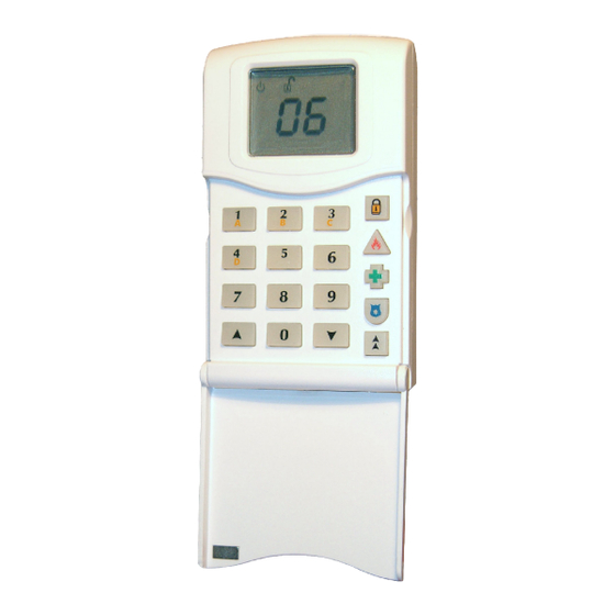
Matrix 6/816 Installation Manual 3. KEYPAD 3.1 Keypad Buttons Numerical buttons To enter user codes and other digital values A, B, C and D To select A, B, C or D arm modes Directional buttons To scroll through the display... -
Page 34: Keypad Indications
Matrix 6/816 Installation Manual 3.2 Keypad Indications Denmark, Norway, Finland & Rest of the World Sweden Supply Illuminated Correct AC & DC power sources AC power is OK Blinking Indicates DC source (battery) fault Indicates an AC fault Indicates AC fault / no power to... -
Page 35: Specifications
Matrix 6/816 Installation Manual 4. SPECIFICATIONS 4.1.1 Matrix 6 ZONES POWER SUPPLY Number of programmable zones – 6 Power input – 17V AC Zone loop types – Normally Open, Normally Closed, Low voltage output 13.8V DC regulated – SEOL, DEOL Max. -
Page 36: Matrix 816
Matrix 6/816 Installation Manual 4.1.2 Matrix 816 ZONES POWER SUPPLY Number of programmable zones – 8, expandable to 16 Power input – 17V AC Zone loop types – Normally Closed, Normally Open, Low voltage output 13.8V DC regulated – SEOL, DEOL Max. -
Page 37: Battery Capacity Calculations
Matrix 6/816 Installation Manual 4.2 Battery Capacity Calculations Maximum Battery recharge time does not exceed 72 hours to satisfy EN50131-6. Total system current (including panel and auxiliary equipment) must not exceed 610mA (panel + Aux + bell + K+). In the event of mains failure EN50131-1:2006+A1:2009 specifies that a stand-by battery should be able to power the system for a non-alarmed period of 12 hours, providing that the prime power source fault is notified to an alarm receiving centre. -
Page 38: Safety & Approvals
Matrix 6/816 Installation Manual 5. SAFETY & APPROVALS SAFETY A technically competent person must carry out the mains installation in accordance with the national and local electrical installation regulations Protective Earth: This equipment must be earthed/grounded Functional Earth: Must be connected to earth terminal to allow the equipment to operate correctly. - Page 40 This product is sold subject to our standard warranty conditions and is warranted against defects in workmanship for a period of 2 years. In the interest of continuing improvement of quality, customer care and design, Pyronix reserves the right to amend specifications without giving prior notice.
Need help?
Do you have a question about the MATRIX 6/816 and is the answer not in the manual?
Questions and answers