Pyronix sterling 10 Installation Manual
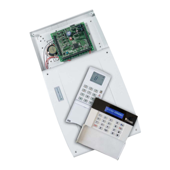
Control panel with remote keypads
Hide thumbs
Also See for sterling 10:
- Installation instructions manual (34 pages) ,
- User manual (24 pages) ,
- Installation instructions (2 pages)

Subscribe to Our Youtube Channel
Related Manuals for Pyronix sterling 10


Summary of Contents for Pyronix sterling 10
- Page 1 STERLING 10 Control Panel with Remote Keypads ICON and LCD INSTALLATION MANUAL IMPORTANT: Please note the Sterling 10 LCD keypad is not compatible for use with the Sterling 10 ICON keypad. RINS1413-1...
- Page 2 Dedicated Website You will have access to a dedicated PI Club section of the Pyronix website which is packed full of features that will keep you updated on Pyronix and industry news.
-
Page 3: Table Of Contents
Sterling 10 Installation Manual CONTENTS 1. INSTALLATION PROCEDURE ........................1 1.1 NVM Reset ............................2 2. WIRING DIAGRAMS..........................3 2.1 Relay PCB Layout & Terminal Connections....................3 2.2 Transistor PCB Layout & Terminal Connections ..................4 2.3 Power & Battery Connections.......................5 2.4 Keypad Connections (LCD Keypad) ......................6 2.5 Keypad Connections (ICON Keypad).....................6... - Page 4 Sterling 10 Installation Manual 7. SYSTEM FAULTS...........................38 7.1 LCD Keypad............................38 7.2 ICON Keypad ............................38 8. QUICK REFERENCE..........................39 8.1 ICON Keypad Programming .......................39 8.2 LCD Keypad Programming .........................40 Page iv RINS1413-1...
-
Page 5: Installation Procedure
1. INSTALLATION PROCEDURE The Sterling 10 is packaged with the transformer and tamper switch. The speaker cover (if a speaker is used), tamper switch pin and cable knock-outs should be removed from the panel prior to fixing to the wall. The following steps illustrate the basic setup procedure for mains and battery connection. -
Page 6: Nvm Reset
Sterling 10 Installation Manual 1.1 NVM Reset To reset the panel back to factory defaults, follow the procedure below. 1. Open the panel, and disconnect the mains power (by removing the fuse from the terminal block) and the battery. 2. Locate the pins marked “NVM RESET”, and short them together using a length of wire or a jumper. -
Page 7: Wiring Diagrams
Sterling 10 Installation Manual 2. WIRING DIAGRAMS NOTE: If a PA button is NOT connected to the system, you MUST link out the PA terminals on the PCB. 2.1 Relay PCB Layout & Terminal Connections SPEAKER VOLUME TUFSMJOH +AUX– +AUX–... -
Page 8: Transistor Pcb Layout & Terminal Connections
Sterling 10 Installation Manual 2.2 Transistor PCB Layout & Terminal Connections +BAT- Connections for Battery Programmable Zone 17V AC Supply Programmable Zone Line Fail Programmable Zone Open/Close +AUX- Auxiliary Supply Confirmed Alarm Tamper Terminal DigiCom Abort Tamper Terminal Outputs FIRE... -
Page 9: Power & Battery Connections
Sterling 10 Installation Manual 2.3 Power & Battery Connections SPEAKER VOLUME TUFSMJOH +AUX– +AUX– Transformer Battery 12V RINS1413-1 Page... -
Page 10: Keypad Connections (Lcd Keypad)
K+ KD K- KT KTR K+ KD K- KT KTR ICON KEYPAD NVM RESET SPEAKER VOLUME TUFSMJOH +AUX- +AUX- IMPORTANT: Please note the Sterling 10 LCD keypad is not compatible for use with the Sterling 10 ICON keypad. Page 6 RINS1413-1... -
Page 11: Belle Connections
Sterling 10 Installation Manual 2.6 Belle Connections SPEAKER VOLUME TUFSMJOH +AUX– +AUX– BELLE NOTE: Ensure that the Belle is selected as Negative Applied (default). RINS1413-1 Page... -
Page 12: Deltabell Connections
Sterling 10 Installation Manual 2.7 Deltabell Connections Page 8 RINS1413-1... -
Page 13: Detector Connections
Sterling 10 Installation Manual 2.8 Detector Connections NOTE 1: Any unused zones must be linked out. NOTE 2: The tamper connections from each detector must be connected in SERIES. SPEAKER VOLUME TUFSMJOH +AUX– +AUX– +AUX- +AUX- Spare SUPPLY SUPPLY ALARM... -
Page 14: Siren Connections
Sterling 10 Installation Manual 2.9 Siren Connections NOTE: If tamper is not used, you MUST link BT to Bell- SPEAKER VOLUME TUFSMJOH +AUX– +AUX– Page 10 RINS1413-1... -
Page 15: Smoke Detector Connections
Sterling 10 Installation Manual 2.10 Smoke Detector Connections NOTE: The zone the detector is connected to must be programmed as Fire. SPEAKER VOLUME TUFSMJOH +AUX– +AUX– Supply Supply Supply 4-Wire Fire 4-Wire Fire 4-Wire Fire Detector Detector Detector NC Output... -
Page 16: Vocaliser Connections
Sterling 10 Installation Manual 2.11 Vocaliser Connections SPEAKER VOLUME TUFSMJOH +AUX– +AUX– +BAT- Page 12 RINS1413-1... -
Page 17: Technical Specifications
Zone loop timers – 0.35 sec. (0.035 sec.) PGM2 – Transistor Open Collector, 10mA @12V Zone activation resistance – not less than 2kOhm CURRENT CONSUMPTION Sterling 10 PCB (alone) – 130mA POWER SUPPLY LCD Remote keypad – 100mA Power input – 17V AC ICON Remote Keypad –... -
Page 18: Safety
Sterling 10 Installation Manual 4. SAFETY SAFETY 5. A technically competent person must carry out the mains installation in accordance with national and local electrical installation regulations. 6. Protective Earth: This equipment must be earthed / grounded. 7. Functional Earth: Provides additional interference protection of a functional purpose only. -
Page 29: Zones
Sterling 10 Installation Manual 6. LCD PROGRAMMING 6.1 Entering/Exiting Engineer Mode Press ENGINEER MODE where is the Enter Engineer mode engineer code (default 9999) Press SYSTEM ARMED SYSTEM ARMED SYSTEM ARMED SYSTEM ARMED SYSTEM ARMED... - Page 30 Sterling 10 Installation Manual 6.2.2 Arm Mode B (Function 11) ENGINEER MODE This starts the function Press 1 ENTRY / EXIT ENGINEER MODE Zone Types: 2 ENTRY / EXIT Entry / Exit ENGINEER MODE Access 3 IMMEDIATE Zone 1 is displayed.
-
Page 31: Timers
Sterling 10 Installation Manual 6.2.4 Arm Mode D (Function 13) ENGINEER MODE This starts the function Press 1 ENTRY / EXIT ENGINEER MODE Zone Types: 2 ACCESS Entry / Exit ENGINEER MODE Access 3 IMMEDIATE Zone 1 is displayed. -
Page 32: Changing Engineer Code (Function 19)
Sterling 10 Installation Manual 6.3.3 Exit Time (Function 16) ENTER SEQUENCE This starts the function Press Enter seconds. ENTER SEQUENCE Example shows 30 seconds. NOTE: Default is 30 seconds. Press You will be returned to engineer mode. -
Page 33: Pgm Programming
Sterling 10 Installation Manual 6.5 PGM Programming 6.5.1 PGM 1 (Function 20) ENTER SEQUENCE This starts the function Press 0 = Not Used Enter the PGM type 1 = PIR Remote LED Enable ENTER SEQUENCE 2 = PIR Latch Memory NOTE: Default is 0 (Not Used). - Page 34 Sterling 10 Installation Manual 6.6.2 System Options 2 (Function 23) ENTER SEQUENCE This starts the function Press ENTER SEQUENCE Use keys to toggle the Example shows option 2 on. options on or off. Press You will be returned to engineer mode.
-
Page 35: Programmable Rearms (Function 26)
Sterling 10 Installation Manual 6.6.4 System Options 4 (Function 25) ENTER SEQUENCE This starts the function Press ENTER SEQUENCE Use keys to toggle the Example shows option 2 off. options on or off. Press You will be returned to engineer mode. -
Page 36: Keyswitch Arm Configuration (Function 28)
Sterling 10 Installation Manual 6.9 Keyswitch Arm Configuration (Function 28) ENTER SEQUENCE This starts the function Press 0 = Arm Mode A 1 = Arm Mode B Enter the required Arm Mode ENTER SEQUENCE 2 = Arm Mode C NOTE: Default is Not Configured. -
Page 37: Anti-Code Algorithm (Function 31)
Sterling 10 Installation Manual 6.12 Anti-Code Algorithm (Function 31) ENTER SEQUENCE This starts the function Press Enter the required Anti-Code Algorithm ENTER SEQUENCE NOTE: This should be left at 0 (Default). The configuration will save automatically. You will be returned to engineer mode. -
Page 38: Final Door Arm Delay (Function 36)
Sterling 10 Installation Manual 6.13.3 Arm Mode C Exit Options (Function 34) ENTER SEQUENCE This starts the function Press Enter the required Exit Option 0 = Timed Exit ENTER SEQUENCE 1 = Push To Arm 2 = Final Door NOTE: Default is 0 (Timed Exit). -
Page 39: System Test
Sterling 10 Installation Manual 6.16 System Test Press a nd use the key to scroll SYSTEM TEST to SYSTEM TEST . Press . The DISPLAY TEST display test starts. SYSTEM TEST To proceed to the strobe test, press any STROBE TEST key. -
Page 40: Change Text
Sterling 10 Installation Manual 6.18 Change Text and use the CHANGE TEXT Press key to scroll to CHANGE TEXT . Press Use the key to scroll to the user, zone or label you wish to edit. -
Page 41: Adjust Brightness
Sterling 10 Installation Manual 6.19 Adjust Brightness and use the ADJUST Press key to scroll to SET BACKLIGHT . Press ADJUST Use the keys to adjust the brightness of the LCD screen. to save the brightness level. -
Page 42: System Faults
Sterling 10 Installation Manual 7. SYSTEM FAULTS There are 4 fault conditions automatically detected by the Sterling 10. 7.1 LCD Keypad The user is informed of a fault via a flashing '!' and an error beep. Press to stop the error beep. The '!' will remain on until the fault has been corrected. -
Page 43: Quick Reference
Sterling 10 Installation Manual 8. QUICK REFERENCE 8.1 ICON Keypad Programming View Log Page 38 Clear Log Page 38 System Test Page 24 Zone Programming – Arm Mode A Page 15 Zone Programming – Arm Mode B Page 16 ... -
Page 44: Lcd Keypad Programming
Sterling 10 Installation Manual 8.2 LCD Keypad Programming View Log Page 38 Clear Log Page 38 Zone Programming – Arm Mode A Page 25 Zone Programming – Arm Mode B Page 25 ... - Page 45 Sterling 10 Installation Manual Adjust Brightness Page 37 RINS1413-1 Page...
- Page 48 This product is sold subject to our standard warranty conditions and is warranted against defects in workmanship for a period of two years. In the interest of continuing improvement of quality, customer care and design, Pyronix Ltd. reserves the right to amend specifications without giving prior notice.
Need help?
Do you have a question about the sterling 10 and is the answer not in the manual?
Questions and answers