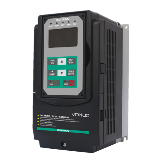
gefran VDI100 Series Instruction Manual
General purpose full vector inverter
Hide thumbs
Also See for VDI100 Series:
- Start-up and installation manual (78 pages) ,
- Instruction manual (38 pages)
Table of Contents
Advertisement
Advertisement
Chapters
Table of Contents

Subscribe to Our Youtube Channel
Related Manuals for gefran VDI100 Series


Summary of Contents for gefran VDI100 Series
- Page 1 General Purpose Full Vector Inverter VDI100 ..Instruction manual...
-
Page 2: Information About This Manual
Keep the manual in a safe place and available to engineering and installation personnel during the product functioning period. Gefran S.p.A has the right to modify products, data and dimensions without notice. The data can only be used for the product description and they can not be understood as legally stated properties. -
Page 3: Table Of Contents
Table of contents Information about this manual ........................2 Software version ..............................2 General information ..............................2 Safety Precautions ..........................5 1.1. Symbols used in the manual ........................5 1.2. Before Supplying Power to the Inverter / Avant d’alimenter le variateur ..........5 1.3. Wiring / Câblage ............................6 1.4. - Page 4 13 - Maintenance Parameters ..............................241 14 - PLC Parameters ................................246 15 - PLC Monitoring Parameters ............................247 16 - LCD Function group ................................248 17 - Automatic Tuning Parameters ............................253 18 - Slip Compensation Parameters............................257 19 - Wobble Frequency Parameters ............................260 20 - Speed Control Parameters ..............................262 21 - Torque And Position Control Parameters ........................271 22 - PM Motor Parameters ..............................280 4.4.1. Annexed 1: Parameters’ default and upper limit values according to the inverter sizes ........283 4.5. Built-in PLC Function ...........................286 4.5.1. Basic Command ..............................286 4.5.2. Basic Command Function ............................287 4.5.3. Application Functions ............................288 4.6. Modbus Protocol Descriptions ......................294 4.6.1.
-
Page 5: Safety Precautions
Safety Precautions Preface • Ensure you have sound knowledge of the device and familiarize yourself with all safety information and precautions before proceeding to operate the inverter. • Please pay close attention to the safety precautions indicated by the warning and caution symbol. Préface Vérifiez que vous avez une bonne connaissance de l’entraînement et de vous familiariser avec les con- •... -
Page 6: Wiring / Câblage
personnel, and should be avoided. To avoid the risk of fire, do not install the inverter on or near flammable objects. Install on nonflammable • objects such as metal surfaces. • If several inverters are placed inside the same control panel, provide adequate ventilation to maintain the temperature below 40°C/104°F (50°C/122°F) without a dust cover) to avoid overheating or fire. -
Page 7: Before Operation / Avant L'opération
Ne pas effectuer un test de tenue en tension diélectrique (mégohmmètre) sur le variateur ou cela va entraî- • ner des dommages de lecture pour les composants semi-conducteurs. The line voltage applied must comply with the inverter’s specified input voltage. (See product nameplate • section 2.1) Caution • Connect braking resistor and braking unit to the designated terminals. (See section 3.10) Do not connect a braking resistor directly to the DC terminals P (+) and N (-), otherwise fire may result. •... -
Page 8: Parameters Setting / Configuration Paramètre
Parameters Setting / Configuration Paramètre 1.5. • Do not connect a load to the motor while performing a rotational auto-tune. Make sure the motor can freely run and there is sufficient space around the motor when performing a rota- • Caution tional auto-tune. Attention ! Ne branchez pas une charge pour le moteur tout en effectuant un auto-tune. -
Page 9: Maintenance, Inspection And Replacement / Entretien, Inspection Et Remplacement
result. • Note the parameter settings related to the braking unit when applicable. • Do not use the inverter braking function for mechanical holding, otherwise injury may result. • Do not check signals on circuit boards while the inverter is running. Attention ! Ne touchez pas les composants générant de la chaleur tels que radiateurs et des résistances de freinage. - Page 10 Attention ! Jeter cet appareil avec soin comme un déchet industriel et selon les réglementations locales nécessaires. • Les condensateurs du circuit principal d’entraînement et circuits imprimés sont considérés comme des • déchets dangereux et ne doivent pas être brûlés. L’enveloppe et d’autres éléments en plastique du variateur, tels la plaque de revêtement supérieure, dé- • gagent des fumées toxiques en cas d’incinération. VDI100 • Instruction manual...
-
Page 11: Model Description
Model Description 2.1. Nameplate Data It is essential to verify the VDI100 inverter nameplate and make sure that the VDI100 inverter has the correct rating so it can be used in your application with the proper sized AC motor. Unpack the VDI100 inverter and check the following: (1) The VDI100 inverter and start-up and installation manual are contained in the package. - Page 12 400V Class Voltage VDI100 Model Applied Motor Filter (HP) (kW) with without VDI100-1007 0.75 • VDI100-1015 • VDI100-1022 • VDI100-2037 • VDI100-2055 • VDI100-3075 • 3ph, 380~480V +10%/-15% VDI100-3110 • 50/60Hz VDI100-4150 • VDI100-4185 18.5 • VDI100-4220 • VDI100-5300 • VDI100-5370-KXX-4-F •...
-
Page 13: Environment And Installation
Environment and Installation 3.1. Environment The environment will directly affect the proper operation and the life span of the inverter. To ensure that the inverter will give maximum service life, please comply with the following environmental conditions: Protection Protection Class IP20/NEMA 1 or IP00 Operating Temperature Ambient Temperature: (-10°C - +40°C (14 -104 °F) -
Page 14: External View
rial rated for this temperature. La température du dissipateur de chaleur de l’inverseur peut atteindre 194°F / 90°C pendant le fonctionnement ; veiller à utiliser un matériau isolant compatible avec cette température. 3.3. External View (a) Sizes 1 and 2 (230V Class: 0.75 ~ 5.5 kW / 400V Class: 0.75 ~ 5.5 kW) Fan cover Fan cover Anti-dust cover Mounting hole Mounting hole Heatsink Rings (4 rings) Front cover Front cover Keypad Keypad Nameplate Nameplate and barcode and barcode Terminal Terminal cover cover (Wall-mounted type, IEC IP20) (Wall-mounted type, IEC IP20, NEMA1) - Page 15 (c) Size 5 (230V Class: 22 kW / 400V Class: 30 ~ 55 kW) (Wall-mounted type, IEC IP20, NEMA1) (d) Size 6 (400V Class: 75 ~ 90 kW and models with “NEMA 1 kit for VDI100”) (Wall-mounted type, IEC IP20) (Wall-mounted type, IEC IP20, NEMA1) (e) Size 7 (400V Class: 110 ~ 160 kW and models with “NEMA 1 kit for VDI100”) (Wall-mounted type, IEC IP00) (Wall-mounted type, IEC IP20, NEMA1) VDI100 • Instruction manual...
-
Page 16: Warning Labels
3.4. Warning Labels Warning information located on the front cover must be read upon installation of the inverter. Lors de l’installation de l’inverseur, lire les avertissements apposés sur le cache de façade. Important (a) Drive sizes 1, 2 and 3 WARNING / AVERTISSEMENT Risk of electrical shock. Shut off main power and wait for 5 minutes before servicing. Risque de choc électrique. -
Page 17: Standard Type
3.5.1. Standard Type (a) Sizes 1 and 2 (230V Class: 0.75 ~ 5.5 kW / 400V Class: 0.75 ~ 5.5 kW) Step 1: Unscrew Step 2: Remove cover Step 3: Make wire connections and place cover back Step 4: Fasten screw (b) Sizes 3 and 4 (230V Class: 7.5 ~ 18.5 kW / 400V Class: 7.5 ~ 22 kW) Step 1: Unscrew cover Step 2: Remove cover VDI100 • Instruction manual... - Page 18 Step 3: Make wire connections and place cover back Step 4: Fasten screw (c) Size 5 (230V Class: 22 kW / 400V Class: 30 ~ 55 kW) Step 1: Unscrew cover Step 2: Remove cover Step 3: Make wire connections and place cover back Step 4: Fasten screw VDI100 • Instruction manual...
-
Page 19: Add-On Filter Type (400V Class: 0.75 ~ 45 Kw)
(d) Sizes 6 and 7 (400V Class: 75 ~ 160 kW) Step 1: Unscrew cover Step 2: Remove cover Step 3: Make wire connections and place cover back Step 4: Fasten screw Add-on filter type (400V Class: 0.75 ~ 45 kW) 3.5.2. Step 1: Unscrew cover Step 2: Remove cover VDI100 •... -
Page 20: Wire Gauges And Tightening Torque
To comply with UL standards, use UL approved copper wires (rated 75° C) and round crimp terminals (UL List- ed products) as shown in table below when connecting to the main circuit terminals. Gefran recommends using crimp terminals manufactured by NICHIFU Terminal Industry Co., Ltd and the terminal crimping tool recom- mended by the manufacturer for crimping terminals and the insulating sleeve. -
Page 21: Wiring Peripheral Power Devices
Terminal Model of the round Model of insulating Model of Wire size Fastening torque screw size crimp terminal sleeve crimp tool (AWG) kgf.cm (in.lbs) R14-4 12.2 to 14 (10.4 to 12.1) TIC 14 NH 1 / 9 R14-5 20.4 to 24 (17.7 to 20.8) TIC 14 NH 1 / 9 14 (6) - Page 22 230V Class : 7.5kW / 400V Class: 7.5~15 kW 230V Class : 11~18.5 kW / 400V Class: 18.5~22kW Disconnect the ground wire of isolated metal plate. Disconnect the ground wire of isolated metal plate. 230V Class : 22kW / 400V Class: 30~55 kW 400V Class: 75 kW and the above Disconnect the ground wire of isolated metal plate.
- Page 23 Input Noise filter: • A filter must be installed when there are inductive loads affecting the inverter. The inverter meets EN 61800-3:2012, category C3 or C2 when the Gefran special filter is used. See section 11.3. Inverter: • Output terminals T1, T2, and T3 are connected to U, V, and W terminals of the motor. If the motor runs in reverse while the inverter is set to run forward, swap any two terminals connections for T1, T2, and T3.
-
Page 24: General Wiring Diagram
3.8. General Wiring Diagram AC Input Voltage Braking Resistor L1(R) L2(S) L3(T) B1/P B2 *1 3ph Induction motor L1/R U/T1 L2/S V/T2 L3/T W/T3 Ground < 100Ω Main Power Section FWD / STOP Analog REV / STOP Output 1 Analog Outputs Multi-Step Speed Ref. - Page 25 230V Class: 2.2~22kW, 400V Class: 3.7~160kW, Description of User Terminals Type Terminal Terminal Function Signal Level / Information 2-wire forward/ stop (default) * 1 2-wire reversal/ stop (default) * 1 Signal Level 24 VDC Multi-speed/ position setting command 1 (default) * 1 (photo isolated) Multi-speed/ position setting command 2 (default) * 1 Digital input...
-
Page 26: Power Terminals
• Maximum output current capacity for terminal 10V is 20mA. • Multi-function analog output AO1 and AO2 are used for an analog output meter. Do not use these outputs Caution for feedback control. • Control board’s 24V and ±10V are to be used for internal control only, Do not use the internal power-supply to power external devices. - Page 27 230V Class: 22kW, 400V Class: 37 ~ 55kW Terminal screw size 400V Class: 75kW Terminal screw size 400V Class: 90kW Terminal screw size 400V Class: 132~160kW Terminal screw size Note ! For wire gauges and screw torques, please refer to the table in section 3.6 VDI100 •...
-
Page 28: Input / Output Power Section Block Diagram
Input / Output Power Section Block Diagram 3.11. The following diagrams 1 - 5 show the basic configuration of the power sections for the range of power and input voltages. This is shown for reference only and is not a detailed description. DC power supply All the VDI100 ranges below can be power supply from DC link: - 230V 3ph up to 22kW, - 400V 3ph up to 90kW Note ! -
Page 29: Cooling Fan Supply Voltage Selection (400V Class)
: 400V Class: 110-132-160 kW DC Link L1/R Reactor U/T1 L2/S V/T2 L3/T W/T3 Control DC /DC Circuit Converter AC/DC Cooling Fan Main Power Section 3.11.1. Cooling Fan Supply Voltage Selection (400V class) The inverter input voltage range of the VDI100 400V class models ranges from 380 to 480Vac. In these models the cooling fan is directly powered from the power supply. -
Page 30: Inverter Wiring
3.12. Inverter Wiring Wiring Precautions • Do NOT remove any protective covers or attempt any wiring while input power is applied. Connect all Warning wiring before applying input power. When making wiring changes after power up, remove input power and wait a minimum of five minutes after power has been turned off before starting. Also confirm that the charge lamp is off and that DC voltage between terminals B1/P or (+) and (-) does not exceed 25V, other- wise electric shock may result. -
Page 31: Input Power And Motor Cable Length
3.13. Input Power and Motor Cable Length The length of the cables between the input power source and /or the motor and inverter can cause a significant phase to phase voltage reduction due to the voltage drop across the cables. The wire size shown in Tables 3.16.1 is based on a maximum voltage drop of 2%. - Page 32 Wire section (mm Class VDI100 Model Grounding line Main circuit Control line E(G) VDI100-1007-KBX-4 2.5~6 2.5~6 0.5~2.5 VDI100-1015-KBX-4 2.5~6 0.5~2.5 VDI100-1022-KBX-4 2.5~6 0.5~2.5 VDI100-2037-KBX-4 2.5~6 0.5~2.5 VDI100-2055-KBX-4 0.5~2.5 VDI100-3075-KBX-4 0.5~2.5 VDI100-3110-KBX-4 0.5~2.5 VDI100-3150-KBX-4 0.5~2.5 VDI100-4185-KBX-4 0.5~2.5 400V VDI100-4220-KBX-4 0.5~2.5 3 Ph VDI100-5300-KBX-4 0.5~2.5 VDI100-5370-KXX-4...
- Page 33 Fig. 3.17.2: Photo-Coupler Connected to an External Relay (5) In Section 3.8 the control boards referenced have a jumper SW3 that can select the digital input to terminals - , to be set for SINK or SOURCE. The following Fig. 3.17.3 (a.) – (d.) shows examples for the various SINK / Source interfaces.
- Page 34 Inverter Specifications 3.18. Single-Phase - 230V Class Sizes VDI100 1007 1015 2022 Rated Output Capacity Rated Output Current Maximum Applicable Motor 0.75 Rated Output Capacity Rated Output Current Maximum Applicable Motor Maximum Output Voltage Three-Phase, 200V to 240V Maximum Output 0.1~599 (Based on parameter setting) Frequency Rated Voltage, Frequency Single-Phase, 200V to 240V, 50/60Hz...
- Page 35 Three phase - 400V Class Sizes VDI100 Rated Output Capacity 11.3 13.7 18.3 23.6 29.7 34.3 45.7 57.2 69.3 85.4 114 137 165 198 225 Rated Output Current 9.2 14.8 118 150 180 216 260 295 100 125 150 175 215 Maximum Applicable Motor 0.75 1.5...
-
Page 36: Powerloss
3.18.1. Powerloss Watt Loss Heat Loss Carrier Frequency Drive Model (kcal/hr) (kHz) Single phase / Three phase - 230V Class VDI100-1007-...-2T-… 107,0 92,0 VDI100-1015-...-2T-… 145,5 125,1 VDI100-2022-...-2T-… 166,6 143,3 Three phase - 230V Class VDI100-2037-...-2T-… 288,0 247,7 VDI100-2055-...-2T-… 461,2 396,6 VDI100-3075-...-2T-…... -
Page 37: General Specifications
3.18.2. General Specifications Motor type Asynchronous Motor, Surface Permanent Magnet Motor, Interior Permanent Magnet Motor Control Modes V/f, V/f+Encoder, SLV (vector control open loop), SV (vector control closed loop), PMSLV, PMSV ±1% (SLV, overload 200% and control range 1 : 30 (60..2Hz ; 50...1.6Hz)), Speed control accuracy ±1% (SLV, overload 150% and control range 1 : 50 (60..1.2Hz ;... -
Page 38: Inverter Derating Based On Carrier Frequency
3.19. Inverter Derating Based on Carrier Frequency 230V Class 0.75 ~ 15 kW 18.5 kW Iout Iout 80% of HD 80% of HD 0 2kHz 6kHz 12kHz 0 2kHz 8kHz 16kHz 22 kW Iout 80% of HD 0 2kHz 5kHz 12kHz 400V Class 0.75 ~ 22 kW... -
Page 39: Inverter Derating Based On Temperature
160 kW Iout 70% of HD 0 2kHz 3kHz 8kHz 3.20. Inverter Derating Based on Temperature Iout 80% of ND IP00 and IP20 without anti-dust covers: 80% of HD >50 °C up to Max.60 °C, 2% derate per °C. Temperature 60°C 50°C Iout... -
Page 40: Inverter Dimensions
3.22. Inverter Dimensions Sizes 1 and 2 (IP20/NEMA1) Dimensions in mm (inch) Net Weight kg Inverter Model (lbs) VDI100-1007-KBX-2T 130 (5.12) 215 (8.46) 150 (5.91) 118 (4.65) 203 (7.99) 5 (0.20) 2.2 (4.9) VDI100-1015-KBX-2T 130 (5.12) 215 (8.46) 150 (5.91) 118 (4.65) 203 (7.99) 5 (0.20) 2.2 (4.9) VDI100-2022-KBX-2T... - Page 41 Size 5 (IP20/NEMA1) Dimensions in mm (inch) Net Weight Inverter Model kg (lbs) VDI100-5220-KXX-2T 286.5 (11.29) 525 (20.67) 252 (9.92) 220 (8.66) 505 (19.88) 3.3 (0.13) 30 (66.14) VDI100-5300-KBX-4 286.5 (11.29) 525 (20.67) 252 (9.92) 220 (8.66) 505 (19.88) 3.3 (0.13) 30 (66.14) VDI100-5370-KXX-4 286.5 (11.29) 525 (20.67)
- Page 42 Sizes 6 and 7 + NEMA 1 kit (IP20/NEMA1) Dimensions in mm (inch) Net Weight Inverter Model kg (lbs) VDI100-6750-KXX-4 348.5 (13.72) 740 (29.13) 300 (11.81) 250 (9.84) 560 (22.05) 1.6 (0.06) 49.7 (109.57) + NEMA 1 kit for VDI100 VDI100-6900-KXX-4 348.5 (13.72) 740 (29.13) 300 (11.81) 250 (9.84) 560 (22.05) 1.6 (0.06) 49.7 (109.57)
-
Page 43: Dimensions For Models With Add-On Filter
Dimensions for Models with Add-on filter 3.23. Sizes 1 and 2 Dimensions in mm (inch) Net Weight Inverter Model kg (lbs) VDI100-1007 130 (5.12) 306 (12.05) 150 (5.91) 118 (4.65) 203 (7.99) 215 (8.46) 3.5 (7.71) VDI100-1015 130 (5.12) 306 (12.05) 150 (5.91) 118 (4.65) 203 (7.99) - Page 44 Size 5 Dimensions in mm (inch) Net Weight Inverter Model kg (lbs) VDI100-5300 286.5 (11.28) 679 (26.73) 252 (9.92) 220 (8.66) 505 (19.88) 525 (20.67) 3.3 (0.13) 32.5 (71.65) VDI100-5370-KXX-4-F 286.5 (11.28) 679 (26.73) 252 (9.92) 220 (8.66) 505 (19.88) 525 (20.67 3.3 (0.13) 32.5 (71.65)
-
Page 45: Keypad And Programming Functions
Keypad and Programming Functions (KB-LED-VDI100) 4.1. LED Keypad 4.1.1. Keypad Display and Keys Reverse Direction External Sequence Forward Direction Status Indicator Indicator Status Indicator External Reference Fault Status Indicator Indicator 5 Digit, 7 Segment LED Display 8 button Membrane Keypad Run Status Indicator Stop Status... -
Page 46: Seven Segment Display Description
4.1.2. Seven Segment Display Description Actual LED Display Actual LED Display Actual LED Display Actual LED Display ° Display output frequency Frequency Reference Set Frequency Reference LED lights on LED flashes Flashing digit At power-up, the display will show the frequency reference setting and all LEDs are flashing. Press the ▲ (UP) or ▼... -
Page 47: Led Indicator Description
4.1.3. LED Indicator Description • Fault LED State Description No Fault Illuminated Fault or alarm Active Forward LED (FWD) • State Description Inverter in reverse direction Illuminated Inverter is running in forward direction Flashing Forward direction active, no run command Reverse LED (REV) •... -
Page 48: Power-Up Monitor
4.1.4. Power-up Monitor • Power-up DSP/FUN DSP/FUN After 3 sec. Switch Mode Display at Power-up Frequency Reference Parameter Selection • Changing Monitor at Power-up 12-00 Display Selection Highest bit -> 0 0 0 0 0 <- Lowest bit The setting range for each bit is 0 ~ 7 from the highest bit to the lowest bit. 0: No display 4: Temperature Range... -
Page 49: Modifying Parameters/ Set Frequency Reference
4.1.5. Modifying Parameters/ Set Frequency Reference Example: Modifying Parameters Frequency Reference Press DSP/FUN Press </RESET Press </RESET ▲ Press Press ▲ READ/ENTER Press Press READ/ENTER Flashing Press DSP/FUN for 3 sec. Example: Set Frequency Reference Display Voltage Class Display Voltage Class Flashing for 3 seconds Flashing for 3 seconds ▲... -
Page 50: Operation Control
4.1.6. Operation Control Stopped Running Stopping Stopped Output Frequency R E V c o m m a n d F W D c o m m a n d R U N c o m m a n d R E V c o m m a n d F W D c o m m a n d S t o p c o m m a n d P o w e r o n... -
Page 51: Lcd Keypad (Kb-Lcd-Vdi100)
4.2. LCD Keypad (KB-LCD-VDI100) 4.2.1. Keypad Display and Keys Reverse Direction External Sequence Forward Direction Status Indicator Indicator Status Indicator External Reference Fault Status Indicator Indicator LCD Display Monitor Fref Ref 12-16=005.00Hz 12-17=000.00Hz 12-18=0000.0A 8 button Run Status Membrane Keypad Indicator Stop Status Indicator DISPLAY... -
Page 52: Keypad Menu Structure
4.2.2. Keypad Menu Structure Main Menu The VDI100 inverter main menu consists of two main groups (modes). The DSP/FUN key is used to switch between the monitor mode and the parameter group mode. Power On Power-up Monitor Mode Parameter Group Mode Mode Description Monitor Mode... - Page 53 To scroll through the available monitor parameter list, press and hold the ▲(up) or ▼ (down) key. Note ! Programming Mode In programming mode inverter parameters can be read or changed. See Fig 4.2.2.3 for keypad navigation. Power ON Monitor Freq Ref 12-16=005.00Hz 12-17=000.00Hz...
-
Page 54: Notes
Auto-tuning Mode In the auto-tuning mode motor parameters can be calculated and set automatically based on the selected con- trol mode. See Fig 4.2.2.4 for keypad navigation. Group 17 Auto-tuning 18 Slip Compen 19 Traverse Func. READ E NT ER Press ▲... - Page 55 (d) The RUN LED (in the upper left corner of the RUN key) will be lit during auto-tuning. (e) The LCD display shows “>>>” or “Atund” during the auto-tuning process. 4. Press the STOP key on the keypad to abort the auto-tuning operation. 5.
-
Page 56: Parameters
4.3. Parameters Parameter group Group Name Group 00 Basic Parameters Group 01 V/f Control Parameters Group 02 IM Motor Parameters Group 03 External Digital Input and Output Parameters Group 04 External Analog Input and Output Parameters Group 05 Multi-Speed Parameters Group 06 Automatic Program Operation Parameters Group 07... - Page 57 Group 00: Basic Parameters Control mode Code Parameter Name Setting Range Default Unit Attribute SLV2 0: V/f 1: V/f+PG 2: SLV 00-00 Control Mode Selection 3: SV 4: PMSV 5: PMSLV 6: SLV2 0: Forward 00-01 Motor’s Rotation Direction 1: Reverse 0: Keypad 1: External Terminal (Control Circuit) Main Run Command Source...
- Page 58 Group 00: Basic Parameters Control mode Code Parameter Name Setting Range Default Unit Attribute SLV2 00-21 Acceleration time 3 0.1~6000.0 00-22 Deceleration time 3 0.1~6000.0 00-23 Acceleration time 4 0.1~6000.0 00-24 Deceleration time 4 0.1~6000.0 Switch-Over Frequency of 00-25 0.00~599.00 Acc/Dec Time 1 and Time 4 00-26 Emergency Stop Time 0.1~6000.0...
- Page 59 Group 01: V/f Control Parameters Control mode Code Parameter Name Setting Range Default Unit Attribute SLV2 01-00 V/f Curve Selection 0~FF 01-01 Reserved Maximum Output Frequen- 01-02 5.0~599.0 60.0 cy of Motor 1 230V: 0.1~255.0 Maximum Output Voltage of 01-03 220.0 Motor 1 400V: 0.2~510.0...
- Page 60 Group 02: IM Motor Parameters Control mode Code Parameter Name Setting Range Default Unit Attribute SLV2 02-00 Control mode selection 0.01~600.00 Modes of V/f, V/f+PG are 10%~200% of inverter’s rated current. Modes of SLV, 02-01 Rated Current of Motor1 SV are 25%~200% of inverter’s rated current.
- Page 61 Group 03: External Digital Input and Output Parameters Control mode Code Parameter Name Setting Range Default Unit Attribute SLV2 0: 2-Wire Sequence (ON: Forward Run Command). 1: 2-Wire Sequence (ON: Reverse Run Command). Multi-Function 2: Multi-Speed/Position Setting Command 1 03-00 Terminal Function Setting-S1 3: Multi-Speed/Position Setting Command 2...
- Page 62 Group 03: External Digital Input and Output Parameters Control mode Code Parameter Name Setting Range Default Unit Attribute SLV2 51: Mode Switching between Speed and Position 52: Multi Position Reference Enable 53: 2-Wire Self Holding Mode (Stop Com- mand) 54: Reserved 55: Reserved 56: Reserved Multi-Function...
- Page 63 Group 03: External Digital Input and Output Parameters Control mode Code Parameter Name Setting Range Default Unit Attribute SLV2 29 : During Traverse Operation Status 30 : Motor 2 Selection 31: Zero Speed Servo Status (Position Mode) 32: Communication Control Contacts 33: Reserved 34: Reserved 35: Reserved...
- Page 64 Group 03: External Digital Input and Output Parameters Control mode Code Parameter Name Setting Range Default Unit Attribute SLV2 03-33 Pulse Input Bias -100.0~100.0 03-34 Filter Time of Pulse Input 0.00~2.00 Function Setting of Pulse 03-35 1: Frequency Command Output 2: Output Frequency 3: Output Frequency after Soft-Start 4: Motor Speed...
- Page 65 Group 04: External Analog Input and Output Parameters Control mode Code Parameter Name Setting Range Default Unit Attribute SLV2 14: Positive / Negative Torque Limit 15: Torque Reference/ Torque Limit (in Speed Control) 16: Torque Compensation 17: PTC Overheat Protection AI2 Signal Scanning and 04-06 0.00~2.00...
- Page 66 Group 05: Multi-Speed Parameters Control mode Code Parameter Name Setting Range Default Unit Attribute SLV2 0: Acceleration and deceleration time are Acceleration and Decelera- set by 00-14 ~ 00-24 05-00 tion Selection of Multi-Spe- 1: Acceleration and Deceleration Time are set by 05-17 ~ 05-48 *Frequency Setting of 05-01...
- Page 67 Group 05: Multi-Speed Parameters Control mode Code Parameter Name Setting Range Default Unit Attribute SLV2 Deceleration Time Setting 05-30 0.1~6000.0 10.0 of Multi Speed 6 Acceleration Time Setting 05-31 0.1~6000.0 10.0 of Multi Speed 7 Deceleration Time Setting 05-32 0.1~6000.0 10.0 of Multi Speed 7 Acceleration Time Setting...
- Page 68 Group 06: Automatic Program Operation Parameters Control mode Code Parameter Name Setting Range Default Unit Attribute SLV2 5: Execute continuous cycle operation. Restart speed is based on the Speed-Sta- ge 0. 6: After completion of a single cycle, the on-going operation speed is based on the speed of the last stage.
- Page 69 Group 06: Automatic Program Operation Parameters Control mode Code Parameter Name Setting Range Default Unit Attribute SLV2 Operation Time Setting of 06-28 0.0~6000.0 Speed-Stage 12 Operation Time Setting of 06-29 0.0~6000.0 Speed-Stage 13 Operation Time Setting of 06-30 0.0~6000.0 Speed-Stage 14 Operation Time Setting of 06-31 0.0~6000.0...
- Page 70 Group 06: Automatic Program Operation Parameters Control mode Code Parameter Name Setting Range Default Unit Attribute SLV2 0: Stop Operation Direction Se- 06-47 1: Forward lection of Speed-Stage 15 2: Reverse * If the maximum output frequency of motor is over 300HZ,the frequency resolution is changed to 0.1Hz Group 07: Start /Stop Parameters Control mode Code...
- Page 71 Group 07: Start /Stop Parameters Control mode Code Parameter Name Setting Range Default Unit Attribute SLV2 0: Not Allowable to Run Run Command Selection at 07-29 the Action of DC Braking 1: Allowable to Run 0: Disable 07-30 Low Voltage Level Selection 1: Enable **Low Voltage Run Fre- 07-31...
- Page 72 Group 08: Protection Parameters Control mode Code Parameter Name Setting Range Default Unit Attribute SLV2 0: Stop Output after Overload Protection Start-up Mode of Overload 08-06 1: Continuous Operation after Overload Protection Operation (OL1) Protection. 08-07 Reserved 0: Enable Automatic Voltage Regula- 08-08 tion (AVR) 1: Disable...
- Page 73 Group 08: Protection Parameters Control mode Code Parameter Name Setting Range Default Unit Attribute SLV2 08-26 Reserved 08-29 0: Deceleration to Stop Digital Input Stop Command 08-30 Selection 1: Coast to Stop 08-31 08-32 Reserved 08-33 08-34 Motor Overheat Fault 08-35 0: Disable Selection...
- Page 74 Group 09: Communication Parameters Control mode Code Parameter Name Setting Range Default Unit Attribute SLV2 Communication Error 09-06 0.0~25.5 Detection Time 0: Deceleration to Stop Based on Decele- 09-07 Fault Stop Selection ration Time 1 when Communication Fault Occurs. 1: Coast to Stop when Communication Fault Occurs.
- Page 75 Group 10: PID Parameters Control mode Code Parameter Name Setting Range Default Unit Attribute SLV2 PID Feedback Loss Det. 10-13 0.0~10.0 Time 10-14 PID Integral Limit 0.0~100.0 100.0 10-15 Reserved 10-16 *Start Frequency of PID 10-17 0.00~599.00 0.00 Sleep 10-18 Delay Time of PID Sleep 0.0~255.5 *Frequency of PID Waking 10-19...
- Page 76 Group 10: PID Parameters Control mode Code Parameter Name Setting Range Default Unit Attribute SLV2 10-36 Reserved 10-38 *Output Frequency Setting 10-39 00.00~599.00 30.00 of PID Disconnection 0: Disable Selection of PID Sleep Com- 10-40 pensation Frequency 1: Enable * If the maximum output frequency of motor is over 300HZ,the frequency resolution is changed to 0.1Hz Group 11: Auxiliary Parameters Control mode Code...
- Page 77 Group 11: Auxiliary Parameters Control mode Code Parameter Name Setting Range Default Unit Attribute SLV2 Frequency Gain of Over 11-28 1~200 Voltage Prevention 2 11-29 Auto De-rating Selection 0: Disable 1: Enable Variable Carrier Frequency 11-30 2~16 Max. Limit Variable Carrier Frequency 11-31 1~16 Min.
- Page 78 Group 11: Auxiliary Parameters Control mode Code Parameter Name Setting Range Default Unit Attribute SLV2 1: When Operator’s UP/DOWN is Enabled, it will be Enabled after Frequency Modi- fication. 11-57 Reserved Record Reference Fre- 11-58 0: Disable quency 1: Enable Gain of Preventing Oscil- 11-59 0.00~2.50...
- Page 79 Group 12: Monitoring Parameters Control mode Code Parameter Name Setting Range Default Unit Attribute SLV2 2: xxxFL (flow) 1500/ 12-03 Line Speed Display (LED) 0~65535 1800 Modes of Line Speed 12-04 0: Display Inverter Output Frequency Display (LED) 1: Display Line Speed with integer (xxxxx) 2: Display Line Speed with the First Decimal Place (xxxx.x) 3: Display Line Speed with the Second...
- Page 80 Group 12: Monitoring Parameters Control mode Code Parameter Name Setting Range Default Unit Attribute SLV2 Motor’s rotation speed = output power x (120/motor’s pole number) In PG/SV mode, motor’s rotation speed is calculated by feedback frequency. Max limit is 65535 12-23 Output Power Factor (Pfo) Display the current output power factor 12-24 Control Mode...
- Page 81 Group 12: Monitoring Parameters Control mode Code Parameter Name Setting Range Default Unit Attribute SLV2 1: CRC Error 1: Data length Error 1: Data Function Error 12-42 RS-485 Error Code 1: Parity Error 1: Overrun Error 1: Framing Error 1: Time out Error Reserved 1: Inverter ready 1: During running...
- Page 82 Group 12: Monitoring Parameters Control mode Code Parameter Name Setting Range Default Unit Attribute SLV2 12-78 Z-Phase Bias Value -9999~9999 Pulse 12-79 Pulse Input Percentage 0.0~100.0 *: Refer to the following attachment 1 ** VDI100 230V Class 37 kW (50HP), and the above, 400V Class 75 kW (100HP) and the above, don’t support heatsink temperature display function. Group 13: Maintenance Parameters Control mode Code...
- Page 83 Group 13: Maintenance Parameters Control mode Code Parameter Name Setting Range Default Unit Attribute SLV2 13-22 Previous two Fault History Exhibit Previous two Fault History 13-23 Previous three Fault History Exhibit Previous three Fault History 13-24 Previous four Fault History Exhibit Previous four Fault History 13-25 Previous five Fault History Exhibit Previous five Fault History...
- Page 84 Group 14: PLC Setting Parameters Control mode Code Parameter Name Setting Range Default Unit Attribute SLV2 14-05 T3 Set Value 2 (Mode 7) 0~9999 14-06 T4 Set Value 1 0~9999 14-07 T4 Set Value 2 (Mode 7) 0~9999 14-08 T5 Set Value 1 0~9999 14-09 T5 Set Value 2 (Mode 7) 0~9999...
- Page 85 Group 15: PLC Monitoring Parameters Control mode Code Parameter Name Setting Range Default Unit Attribute SLV2 15-07 T4 Current Value 2 (Mode7) 0~9999 15-08 T5 Current Value 1 0~9999 15-09 T5 Current Value 2 (Mode7) 0~9999 15-10 T6 Current Value 1 0~9999 15-11 T6 Current Value 2 (Mode7) 0~9999 15-12 T7 Current Value 1...
- Page 86 Group 16: LCD Function Parameters Control mode Code Parameter Name Setting Range Default Unit Attribute SLV2 20001~29999: Users specify the format, Input 2XXXX represents the display of XX.XX at 100%. 30001~39999: Users specify the format, Input 3XXXX represents the display of X.XXX at 100%. 16-04 Engineering Unit 0: without using engineering unit 1: FPM...
- Page 87 Group 17: Automatic Tuning Parameters Control mode Code Parameter Name Setting Range Default Unit Attribute SLV2 Mode Selection of Automa- 17-00 0: Rotation Auto-tuning tic Tuning* 1: Static Auto-tuning 2: Stator Resistance Measurement VF:2 VF+PG:2 3: Reserved SLV:6 4: Loop Tuning SV:6 SLV2:6 5: Rotation Auto-tuning Combination...
- Page 88 Group 18: Slip Compensation Parameters Control mode Code Parameter Name Setting Range Default Unit Attribute SLV2 Slip Compensation Filter 18-03 0.0~10.0 Time Regenerative Slip Compen- 18-04 0: Disable sation Selection 1: Enable 18-05 FOC Delay Time 1~1000 18-06 FOC Gain 0.00~2.00 *: Refer to the following attachment 1 Group 19: Wobble Frequency Parameters...
- Page 89 Group 20: Speed Control Parameters Control mode Code Parameter Name Setting Range Default Unit Attribute SLV2 Low-pass Filter Time Con- 20-14 1~1000 stant of Speed Feedback 2 ASR Gain Change Frequen- 20-15 0.0~599.0 cy 1 ASR Gain Change Frequen- 20-16 0.0~599.0 cy 2 Torque Compensation Gain...
- Page 90 Group 21: Torque And Position Control Parameters Control mode Code Parameter Name Setting Range Default Unit Attribute SLV2 21-04 Speed Limit Bias 0~120 21-05 Positive Torque Limit 0~300 21-06 Negative Torque Limit 0~300 Forward Regenerative 21-07 0~300 Torque Limit Reversal Regenerative 21-08 0~300 Torque Limit...
- Page 91 Group 21: Torque And Position Control Parameters Control mode Code Parameter Name Setting Range Default Unit Attribute SLV2 The Command of Rotation 21-36 -9999 ~ 9999 Cycle Number of Section 13 The Command of the Pulse 21-37 -9999 ~ 9999 Number of Section 13 The Command of Rotation 21-38...
-
Page 92: Attachment 1: Parameters' Default Value And Upper Limit Value Are Adjusted By Different Inverter Sizes
Group 22: PM Motor Parameters Control mode Code Parameter Name Setting Range Default Unit Attribute SLV2 2: Auto tune for PMSV Fault History of PM Motor 22-22 0. No Error Tuning 1. Static Magnetic Alignment Fault 2. Without PG Option Card 3. - Page 93 Max. frequency in SLV Max. frequency (Hz) The initial value of pa- when carrier frequency in SLV when carrier Display parameter 12-41 rameter 18-00 in SLV/ SV ≤ 8 kHz frequency > 8 kHz Models Size (Inverter temperature) (Slip compensation at low 11-01 11-01 speed)
-
Page 94: Low Voltage Detection Level Function
400V Class Models 01-09 01-07 01-23 01-21 11-59 11-60 Model Minimum Output Middle Output Minimum Output Middle Output Gain of Preventing Upper Limit of Voltage 1 of Motor 1 Voltage 1 of Motor 1 Voltage 1 of Motor 2 Voltage 1 of Motor 2 Oscillation Preventing Oscillation 1007... -
Page 95: Description Of Parameters
4.4. Description of Parameters 00 - Basic Parameters Code Parameter Name / Range 00-00 Control mode selection 0: V/f 1: V/f+PG 2: SLV 3: SV 4: PMSV 5: PMSLV 6: SLV2 The inverter offers the following control modes: Value Mode Info Application V/f Control without PG... - Page 96 parameters for higher performance operation. Perform auto-tuning before operation to enhance the performance of PMSLV mode. Refer to parameter 22-21 for the descriptions of PM motor tuning function. Select the appropriate motor rating and braking resistor based on your motor and applications. Please install the braking module in the models of 230V Class 22 kW / 400V Class 37 kW or the above.
- Page 97 Terminal S1 Terminal S2 Operation Closed Closed Stop Inverter, Display EF9 Alarm after 500ms Parameter 13-08 to 2, 4 or 6 for 2-wire program initialization, multi-function input terminal S1 is set to forward , operation/ stop, and S2 is set for reverse, operation / stop. Forward, Run / Stop Reverse...
- Page 98 ■ 2-wire operation with hold function To enable 2-wire operation with hold function set any of parameters 03-02 to 03-07 (terminal S3 ~ S8) to 53. When this mode is enabled set terminal S1 (03-00=0) to forward and S2 (03-01=1) to reverse run command. Forward Run Command (On: Run Forward) Reverse Run Command...
- Page 99 Note: It will not restore to the default value when this parameter performs initialization. Code Parameter Name / Range 00-05 Main Frequency Command Source Selection 00-06 Alternative Frequency Source Selection 0: Keypad 1: External control (analog) 2: Terminal UP / DOWN 3: Communication control 4: Pulse input 5: Reserved...
- Page 100 The frequency reference command is set via the RS-485 communication port using the MODBUS RTU proto- col. Refer to parameter group 9 for additional information. 00-05/00-06= 4: Pulse input To use this function a pulse train input is required to be connected to the PI input and GND (see fig. 4.4.5). Set parameter 03-30 to 0 to use the pulse input as frequency reference.
- Page 101 00-10=1: Frequency command is lower than 01-08 (Minimum Output Frequency of Motor 1), inverter run as Minimum Output Frequency of Motor 1. Code Parameter Name / Range 00-11 Selection of PID Lower Limit Frequency [0] PID is bound to lower limit frequency when inverter sleeps. [1] PID is bound to 0Hz when inverter sleeps.
- Page 102 00-22 Deceleration time 3 00-23 Acceleration time 4 00-24 Deceleration time 4 00-25 Switch-Over Frequency of Acceleration and Deceleration Time 1 and Time 4 0.1~6000.0 s Acceleration time is the time required to accelerate from 0 to 100% of maximum output frequency. Deceleration time is the time required to decelerate from 100 to 0% of maximum output frequency.
- Page 103 C. Automatically switch acceleration/deceleration time When output frequency equals to the value of 00-25, it follows the value of 00-25 to automatically switch accel- eration/deceleration time1 and time2. Please refer to the following Figure 4.4.8. Figure 4.4.8 automatically switch Acceleration/Deceleration time Output Frequency 00 - 25 time Tdec4 Tdec1 Tacc1 Tacc4 Rate...
- Page 104 Code Parameter Name / Range 00-26 Emergency stop time 0.0~6000.0 s The emergency stop time is used in combination with multi-function digital input function #14 (Emergency stop). When emergency stop input is activated the inverter will decelerate to a stop using the Emergency stop time (00-26) and display the [EM STOP] condition on the keypad.
- Page 105 440V: 18.5~22 kW 100Hz 220V: 22 kW, 440V: 30~160 kW Carrier frequency (11-01) set 8kHz or below 100Hz 220V: 22 kW, 440V: 30~132 kW Carrier frequency (11-01) set 8kHz or higher 80Hz 00-27= 1: Normal Duty Mode In normal duty mode only applies to control modes V/f and V/f + PG. All other modes must use the Heavy Duty settings.
- Page 106 Parameter Name / Range 00-32 Application Selection ** 0: General 1: Reserved 2: Conveyor 3: Exhaust fan 4: Reserved 5: Compressor 6: Hoist- * Consult Gefran for the settings 7: Crane- * Consult Gefran for the settings VDI100 • Instruction manual...
- Page 107 0: HD 01-00 V/f curve selection 07-00 Momentary stop and restart selection 1: Enable 08-00 Stall prevention function xx0xb: Stall prevention during deceleration 00-32=6: Hoist* Consult Gefran for the detailed settings Parameter Name Value 00-00 Control mode selection 2: SLV 00-05 Main Frequency command source selection 0: keypad...
- Page 108 00-27 HD/ND Mode selection 0: HD 11-01 Carrier frequency 5.0kHz 05-01 Frequency setting of speed-stage 0 6.0 Hz 05-02 Frequency setting of speed-stage 1 30.0 Hz 05-03 Frequency setting of speed-stage 2 60.0 Hz 03-04 Multi-function terminal Function setting-S5 2: Multi-speed/position setting command 1 03-05 Multi-function terminal Function setting-S6 3: Multi-speed/position setting command 2...
- Page 109 00- 44 User parameter 3 00- 45 User parameter 4 00- 46 User parameter 5 00- 47 User parameter 6 00- 48 User parameter 7 00- 48 User parameter 8 00- 50 User parameter 9 00- 51 User parameter 10 00- 52 User parameter 11 00- 53...
- Page 110 Example 2: After one or more parameters in 00-41 ~ 00-56 are set, user parameters settings are as follows. Steps LCD Display Descriptions Group 13 Driver Status Select the start parameter group (03) in the advanced modes. 14 PLC Setting 15 PLC Monitor PARA Press (READ/ ENTER) and ▲ (Up) / ▼ (Down) key to enter the access level of parameter -06.
- Page 111 User Parameter Run Mode Structures A. Define Parameter Group 0~24 as user parameters except parameter 00-00 and 00-41~00-56. [ Main Screen ] [ Main Menu] [ Subdirectory] [ READ/ ENTER ] READ ENTER PARA Monitor Group Freq Ref -00 Control Method 12 –...
-
Page 112: V/F Control Parameters
01 - V/f Control Parameters Code Parameter Name / Range 01-00 V/f curve selection 0~FF The V/f curve selection is enabled for V/f mode with or without PG or SLV2 mode. Make sure to set the inverter input voltage parameter 01-14. There are three ways to set V/f curve: (1) 01-00 = 0 to E: choose any of the 15 predefined curves (0 to E). - Page 113 Table 4.4-A: V/f curve selection (200V) - Sizes 1007-2T / 1015-2T Type Specification 01-00 V/f curve Type Specification 01-00 V/f curve Starting Torque (0),(F) 50Hz 50Hz 14.6 High 50Hz 13.5 Starting (Default Torque (Hz) 0 1.3 (Hz) 1.3 2.5 setting) 60Hz Starting F (60Hz Saturation Torque Default 60Hz 60Hz setting) 14.6 High (1),(F)
- Page 114 Table 4.4-B: V/f curve selection (200V) - Sizes 2022-2T ... 5220-2T Type Specification 01-00 V/f curve Type Specification 01-00 V/f curve Starting Torque (0),(F) 50Hz 50Hz 13.8 High 13.3 50Hz 12.7 Starting (Default (Hz) (Hz) Torque 0 1.3 1.3 2.5 setting) 60Hz Starting F (60Hz Saturation Torque Default 60Hz setting) 60Hz 13.8 (1),(F)
- Page 115 Table 4.4-C: V/f curve selection (220V) - Sizes 1007-2T ... 1015-2T Type Specification 01-00 V/f curve Type Specification 01-00 V/f curve Starting Torque (0),(F) 50Hz 50Hz 16.1 High 15.4 ( 50Hz 14.8 Starting Default (Hz) 0 1.3 Torque (Hz) 1.3 2.5 setting ) 60Hz Starting Saturation ( 60Hz Torque Default 60Hz 60Hz setting )
- Page 116 Table 4.4-D: V/f curve selection (220V) - Sizes 2022-2T ... 5220-2T Type Specification 01-00 V/f curve Type Specification 01-00 V/f curve Starting Torque (0),(F) 50Hz 50Hz 15.2 High 14.6 ( 50Hz Starting Default Torque (Hz) (Hz) 0 1.3 1.3 2.5 setting ) 60Hz Starting Saturation Torque ( 60Hz Default 60Hz 60Hz setting ) 15.2...
- Page 117 Table 4.4-E: V/f curve selection (230V) - Sizes 1007-2T ... 1015-2T Type Specification 01-00 V/f curve Type Specification 01-00 V/f curve Starting Torque (0),(F) 50Hz 50Hz 16.8 High 16.1 ( 50Hz 15.5 Starting Default Torque (Hz) 0 1.3 (Hz) 1.3 2.5 setting ) 60Hz Starting Saturation ( 60Hz Torque Default 60Hz 60Hz setting )
- Page 118 Table 4.4-F: V/f curve selection (230V) - Sizes 2022-2T ... 5220-2T Type Specification 01-00 V/f curve Type Specification 01-00 V/f curve Starting Torque (0),(F) 50Hz 50Hz 15.9 High 15.3 ( 50Hz 14.6 Starting Default Torque (Hz) (Hz) 0 1.3 1.3 2.5 setting ) 60Hz Starting Saturation ( 60Hz Torque Default 60Hz 60Hz setting )
- Page 119 Table 4.4-G: V/f curve selection (380V) - Sizes 1007-4 ... 1015-4 Type Specification 01-00 V/f curve Type Specification 01-00 V/f curve Starting Torque (0),(F) 50Hz 50Hz 27.8 High 26.6 ( 50Hz 25.6 Starting 13.6 13.8 Default (Hz) Torque 0 1.3 (Hz) 1.3 2.5 setting ) 60Hz Starting Saturation ( 60Hz Torque Default 60Hz...
- Page 120 Table 4.4-H: V/f curve selection (380V) - Sizes 1022-4 ... 4220-4 Type Specification 01-00 V/f curve Type Specification 01-00 V/f curve Starting Torque (0),(F) 50Hz 50Hz 26.3 High 25.2 ( 50Hz 24.2 13.3 Starting 13.1 Default Torque (Hz) (Hz) 0 1.3 1.3 2.5 setting ) 60Hz Starting Saturation ( 60Hz Torque Default 60Hz...
- Page 121 Table 4.4-I: V/f curve selection (380V) - Sizes ≥ 5300-4 Type Specification 01-00 V/f curve Type Specification 01-00 V/f curve Starting Torque (0),(F) 50Hz 50Hz 27.6 High 26.4 ( 50Hz 25.9 15.5 Starting 14.7 Default 14.7 (Hz) Torque (Hz) 1.3 2.5 0 1.3 setting ) 60Hz Starting Saturation ( 60Hz Torque Default 60Hz...
- Page 122 Table 4.4-L: V/f curve selection (400V) - Sizes 1007-4 ... 1015-4 Type Specification 01-00 V/f curve Type Specification 01-00 V/f curve Starting Torque (0),(F) 50Hz 50Hz 29.3 High ( 50Hz 26.9 14.7 Starting 14.5 14.4 Default Torque (Hz) 0 1.3 (Hz) 1.3 2.5 setting ) 60Hz Starting Saturation ( 60Hz Torque Default 60Hz...
- Page 123 Table 4.4-M: /f curve selection (400V) - Sizes 1022-4 ... 4220-4 Type Specification 01-00 V/f curve Type Specification 01-00 V/f curve Starting Torque (0),(F) 50Hz 50Hz 27.6 High 26.5 ( 50Hz 25.5 Starting 13.8 13.6 Default Torque (Hz) (Hz) 0 1.3 1.3 2.5 setting ) 60Hz Starting Saturation ( 60Hz Torque Default 60Hz...
- Page 124 Table 4.4-N: V/f curve selection (400V) - Sizes ≥ 5300-4 Type Specification 01-00 V/f curve Type Specification 01-00 V/f curve Starting Torque (0),(F) 50Hz 50Hz 29.1 High 27.8 ( 50Hz 27.3 16.4 Starting 15.5 Default 15.5 (Hz) Torque (Hz) 1.3 2.5 0 1.3 setting ) 60Hz Starting Saturation ( 60Hz Torque Default 60Hz...
- Page 125 Table 4.4-O: V/f curve selection (415V) - Sizes 1007-4 ... 1015-4 Type Specification 01-00 V/f curve Type Specification 01-00 V/f curve Starting Torque (0),(F) 50Hz 50Hz 30.4 High 29.1 ( 50Hz 27.9 15.3 Starting 15.1 14.9 Default Torque (Hz) 0 1.3 (Hz) 1.3 2.5 setting ) 60Hz Starting Saturation ( 60Hz Torque Default 60Hz...
- Page 126 Table 4.4-P: V/f curve selection (415V) - Sizes 1022-4 ... 4220-4 Type Specification 01-00 V/f curve Type Specification 01-00 V/f curve Starting Torque (0),(F) 50Hz 50Hz 28.7 High 27.5 ( 50Hz 26.4 14.5 Starting 14.3 14.1 Default Torque (Hz) (Hz) 0 1.3 1.3 2.5 setting ) 60Hz Starting Saturation ( 60Hz Torque Default 60Hz...
- Page 127 Table 4.4-Q: V/f curve selection (415V) - Sizes ≥ 5300-4 Type Specification 01-00 V/f curve Type Specification 01-00 V/f curve Starting Torque (0),(F) 50Hz 50Hz 30.2 High 28.9 ( 50Hz 28.3 Starting Default (Hz) Torque (Hz) 1.3 2.5 0 1.3 setting ) 60Hz Starting Saturation ( 60Hz Torque Default 60Hz 60Hz setting )
- Page 128 Table 4.4-R: V/f curve selection (440V) - Sizes 1007-4 ... 1015-4 Type Specification 01-00 V/f curve Type Specification 01-00 V/f curve Starting Torque (0),(F) 50Hz 50Hz 32.2 High 30.8 ( 50Hz 29.6 16.2 Starting 15.8 Default Torque (Hz) 0 1.3 (Hz) 1.3 2.5 setting ) 60Hz Starting Saturation ( 60Hz Torque Default 60Hz...
- Page 129 Table 4.4-S: V/f curve selection (440V) - Sizes 1022-4 ... 4220-4 Type Specification 01-00 V/f curve Type Specification 01-00 V/f curve Starting Torque (0),(F) 50Hz 50Hz 30.4 High 29.2 ( 50Hz 15.4 Starting 15.2 Default Torque (Hz) (Hz) 0 1.3 1.3 2.5 setting ) 60Hz Starting Saturation ( 60Hz Torque Default 60Hz 60Hz...
- Page 130 Table 4.4-T: V/f curve selection (440V) - Sizes ≥ 5300-4 Type Specification 01-00 V/f curve Type Specification 01-00 V/f curve Starting Torque (0),(F) 50Hz 50Hz High 30.6 ( 50Hz Starting Default (Hz) Torque 1.3 2.5 (Hz) 0 1.3 setting ) 60Hz Starting Saturation ( 60Hz Torque Default 60Hz 60Hz setting ) High (1),(F)
- Page 131 Table 4.4-U: V/f curve selection (460V) - Sizes 1007-4 ... 1015-4 Type Specification 01-00 V/f curve Type Specification 01-00 V/f curve Starting Torque (0),(F) 50Hz 50Hz 33.7 High 32.2 ( 50Hz 30.9 16.9 Starting 16.7 16.5 Default Torque (Hz) 0 1.3 (Hz) 1.3 2.5 setting ) 60Hz Starting Saturation ( 60Hz Torque Default 60Hz...
- Page 132 Table 4.4-V: V/f curve selection (460V) - Sizes 1022-4 ... 4220-4 Type Specification 01-00 V/f curve Type Specification 01-00 V/f curve Starting Torque (0),(F) 50Hz 50Hz 31.8 High 30.5 ( 50Hz 29.3 16.1 Starting 15.9 15.7 Default Torque (Hz) (Hz) 0 1.3 1.3 2.5 setting ) 60Hz Starting Saturation ( 60Hz Torque Default 60Hz...
- Page 133 Table 4.4-W: V/f curve selection (460V) - Sizes ≥ 5300-4 Type Specification 01-00 V/f curve Type Specification 01-00 V/f curve Starting Torque (0),(F) 50Hz 50Hz 33.5 High ( 50Hz 31.4 18.8 Starting 17.8 Default 17.8 (Hz) Torque 1.3 2.5 (Hz) 0 1.3 setting ) 60Hz Starting Saturation ( 60Hz Torque Default 60Hz...
- Page 134 Code Parameter Name / Range 01-02 Maximum output frequency of motor 1 5.0~599.0 Hz 01-03 Maximum output voltage of motor 1 230V: 0.1~255.0 V 400V: 0.2~510.0 V 01-04 Middle output frequency 2 of motor 1 0.0~599.0 Hz 01-05 Middle output voltage 2 of motor 1 230V: 0.0~255.0 V 400V: 0.0~510.0 V 01-06...
- Page 135 Figure 4.4.13 Torque boosting Output Voltage (V) Vmax Vmid2 Vmid1 Vmin Fmin Fbase Fmid2 Fmax ( 01 - 02 ) ( 01 - 12 (01- 08) ( 01- 04) Fmid1 ( 01 - 06) When setting the frequency related parameters for a custom V/f curve values make sure that: Fmax > Fbase > Fmid2 > Fmid1 >Fmin (01-02) (01-12) (01-04) (01-06) (01-08) The ‘SE03’...
- Page 136 Figure 4.4.14 Torque compensation gain to increase/decrease output torque Output Voltage 100% Torque Increase 01-10 Torque Decrease Base frequency Increase value when: • The wiring between the inverter and the motor very too long • The motor size is smaller than the inverter size Note: Gradually increase the torque compensation value and make sure the output current does not exceed inverter rated current.
- Page 137 Code Parameter Name / Range 01-16 Maximum output frequency of motor 2 5.0~599.0 Hz 01-17 Maximum output voltage of motor 2 230V: 0.1~255.0 V 400V: 0.2~510.0 V 01-18 Middle output frequency 2 of motor 2 0.0~599.0 Hz 01-19 Middle output voltage 2 of motor 2 230V: 0.0~255.0 V 400V: 0.0~510.0 V 01-20...
-
Page 138: Im Motor Parameters
02 - IM Motor Parameters Code Parameter Name / Range 02-00 No-load current of motor 1 0.01~600.00 A 02-01 Rated current of motor 1 V/f and V/f+PG modes are 10%~200% of inverter’s rated current. SLV, SV modes are 25%~200% of inverter’s rated current. 02-03 Rated rotation speed of motor1 0~60000 rpm... - Page 139 Set the motor rpm according to the motor nameplate. (7) No-load motor voltage (02-19) Parameter determines the rated flux during motor’s rated rotation in SLV or SV control mode. Set the value of this parameter to the same value as parameter 17-08. A value of 10~50V below the input voltage level ensures that the motor is capable of providing adequate torque performance when operating at nominal speed (or higher speed).
- Page 140 Figure 4.4.15 Y-equivalent model an induction motor Code Parameter Name / Range 02-20 No-Load Current of motor 2 0.01~600.00 A 02-21 Rated current of motor 2 10%~200% of inverter’s rated current 02-22 Rated rotation speed of motor 2 0~ 60000 rpm 02-23 Rated voltage of motor 2 230V: 50.0~240.0 V 400V: 100.0~480.0 V 02-24...
- Page 141 The default value of motor slip is set to 1.78 Hz. Motor slip is obtained from the nameplate. × × Frequence Take 60Hz, 4-pole motor for example, synchronous speed: 1800 rpm Pole − 1800 1700 Slip Rated speed in the nameplate is 1700 rpm, then Adjusting motor slip will change the rotor resistance parameter.
-
Page 142: External Digital Input And Output Parameters
03 - External Digital Input and Output Parameters Code Parameter Name / Range 03-00 Multi-function terminal function setting – S1 03-01 Multi-function terminal function setting – S2 03-02 Multi-function terminal function setting – S3 03-03 Multi-function terminal function setting – S4 03-04 Multi-function terminal function setting –... - Page 143 63: Reserved 64: Reserved 65: Short-circuit braking Refer to the multi-function digital input and related parameters in the following figure 4.4.16. Figure 4.4.16 Multi-function digital input and related parameters Related Parameters 03-00 03-01 03-02 03-03 03-04 03-05 03-06 03-07 24VG Table 4.4.6 Multi-function digital input setting (03-00 to 03-07) (“O”: Enable, “X”: Disable) Function Control mode Value Description Name LCD Display SLV2 2-wire type (Forward oper-...
- Page 144 Function Control mode Value Description Name LCD Display SLV2 Frequency Command Source Main/ Alternative Frequency is set in parameter of alter- Freq Change Sel Switch Function native frequency command (00-06) Emergency stop (decelerate to E-Stop ON: Emergency stop input zero and stop) External baseblock command Ext.
- Page 145 Function Control mode Value Description Name LCD Display SLV2 Switching between motor 1/ Motor 2 Switch ON: Start motor 2 motor 2 PID Sleep PID Sleep ON: PID Sleep PG disabled PG disabled ON: Speed control without PG ON: Integral value reset of PG integral reset I-Time Reset speed control with PG...
- Page 146 03-0X =05: Multi-speed/position setting command 4 (setting =05). Select frequency reference using multi-function digital input. In SV or PMSV mode (00-00=3, 4), with 03-00~07 set to 51, multi-speed command can be used to select multi- ple segment positions. 03-0X =29: Jog frequency selection (setting =29). Select frequency reference using the multi-function digital input.
- Page 147 Figure 4.4.18: 9-speed timing diagram Frequency Reference (05-08) (05-07) (05-06) aux. speed (05-05) master speed (05-04) (05-03) (05-02) (05-01) (00-18) speed speed speed speed speed speed speed speed speed Termina Forward RUN (S1) Multi - step (S5) speed Ref 1 Multi - step (S6) speed Ref 2 Multi - step (S7)
- Page 148 For the examples of UP/DOWN control wiring and operation, please refer to figure 4.4.19 and 4.4.20. Figure 4.4.19 UP/DOWN wiring and operation example UP Command (Terminal S1 Forward Run / Stop (03-00 = 0) Down Command (Termi- S5 Up Command (03-04=8) nal S6) Operation Accel (UP) Decel (DWN) Hold Hold...
- Page 149 Refer to Figure 4.4.21. for an example. Figure 4.4.21 Inhibit acceleration / deceleration command operation Power Supply Forward Inhibit ACC / DEC Command Frequency Fref 1 Reference Fref Fref 1 Output Fref Frequency Hold Hold 03-0X =12: Main/ Alternative Run Switch Function When function terminals conduct, run command source is set in alternative run command (00-03). When functional terminal is set to 27 (Local/ Remote control selection), it will be precedential to main/alternative run switch.
- Page 150 Figure 4.4.22 External base block operation Command External Baseblock Output Frequency Coast to Coast to stop Speed search active stop 03-0X =16: PID control disabled. 03-0X =17: Fault reset The output becomes active when the inverter trips on a fault. Upon an inverter fault the inverter output will turn off (base block) and the keypad displays the dedicated fault message.
- Page 151 RS485). Use parameter 00-05 (Main frequency command source selection) and 00-02 (Run command selec- tion) to select the remote source. Note: In 3-wire operation terminal S1 and S2 are reserved for run/stop operation and the Local / Remote function can only be set to digital input terminals S3 to S8 (03-02 to 03-07).
- Page 152 Input Ref. Frequency Reference / Run/Stop Command Source Source Pulse Input - Frequency reference set by pulse input Parameter - Frequency reference source selected by parameter 00-05 00-05 Note: - Function is disabled when the Local/Remote selection (25) or Remote mode selection (26) is active. - To switch between local and remote the inverter has to be stopped.
- Page 153 Input Control Torque Control Speed Control 03-0X =45: Negative torque command When input is active reverses torque reference command. Refer to Figure 4.4.128 for more details. 03-0X =46: Zero-servo Command; Start: zero-servo operation. When input is active starts zero-servo operation. Refer to Figure 4.4.129 for more details. 03-0X =47: Fire mode When input is active disables all inverter warning and hardware protections.
- Page 154 03-0X =53: 2-Wire Self-holding Mode (Stop Command) Refer to parameter description of 00-02 (2-wire operation with self-holding function) 03-0X =58: Safety function When safety function is on, the inverter will stop depending on the setting of 08-30 after the digital terminal is active.
- Page 155 03-10= 0: normally open switch s8 s7 s6 s5 1: normally close switch Example: S1 and S2 wired to a normally closed contact / switch set 03-09=0011. Do not set the operation command parameter 00-02 to terminal control before setting the digital input type. Failure to comply may cause death or serious injury.
- Page 156 Figure 4.4.25 Multi-function digital output and related parameters Default function Related parameter Fault signal 03-11 Zero 03-12 speed *use DO2/DOG on Frame 1. Table 4.4.8 Function table of multi-function digital output Function Control mode Setting Contents Name LCD display SLV2 During Running Running ON: During running (Run Command is ON) Fault contact output Fault ON: Fault contact output (except CF00 and CF01 ) ON: frequency agree (frequency agree width detec- Frequency agree...
- Page 157 Function Control mode Setting Contents Name LCD display SLV2 Reserved Invalid Do Func. Reserved Reserved Invalid Do Func. Reserved PID Feedback Loss PID Fbk Loss ON: PID Feedback Loss Detection Output Break Release Brake Release ON: Release Brake Frequency Detection Freq.
- Page 158 Output is active during low torque detection see parameters 08-17 ~ 08-20. 03-1X=13: Current Agree When output current > 03-15 and output current > 03-15 duration >03-16, it is ON. 03-1X=18: PLC status (setting =18) Output is active when operation command parameter (00-02) is set to 3: PLC Control. 03-1X=19: PLC control contact Output is controlled by the PLC logic 03-1X=20: Zero-speed...
- Page 159 erate to a stop. When parameter 11-41 is set to 1 operation will continue at the value of parameter 11-42 times the last know frequency reference. 03-1X=27: Time function output Output is controlled by timer function see parameter 03-37 and 03-38. 03-1X=28: Traverse operation UP status Output is controlled by frequency wobbling operation;...
- Page 160 03-14 Frequency detection width 0.1~25.5 Hz Frequency detection Level: set the multi-function output terminals R1A-R1C, R2A-R2C or PH1 (03-11, 03-12 or 03-28) to the desired detection level and bandwidth for use with multi-function output functions 2 to 5. The time charts for the Frequency Agree Detection operation are shown in the following table 4.4.9. Code Parameter Name / Range 03-44...
- Page 161 Function Detection operation of frequency confirmation Description 03-14 Output Frequency Output is active when the output frequency is below the frequency 03-13 03-13 detection level (03-13) + frequency detection width (03-14) and time turns off when the output frequency falls below frequency detection Output frequency 03-14 level.
- Page 162 Function Detection operation of frequency confirmation Description If the output frequency > frequency detection level (03-13) + fre- 03-14 Output quency detection width (03-14) during acceleration, signal of output Frequency frequency detection 1 (dedicated for Crane) is ON. 03-13 03-13 Output Frequency time If the output frequency <...
- Page 163 When 03-11=14, the real frequency equal to the value of 03-17(Delay Time of Current Agree Detection) in acceleration time, the relay output will execute. When 03-11=14, the real frequency equal to the value of 03-18(Delay Time of Current Agree Detection) in de- celeration time, the relay output will stop execute.
- Page 164 03-27=3: Keep the state of frequency command not to be cleared. When run command re-sends, press UP/DOWN key before the run frequency reaches the frequency command. Code Parameter Name / Range 03-40 Up/Down Frequency Width Setting 0.00~5.00 Hz When 03-40 is set to 0 Hz, Up / Down function is maintained. When 03-40 is not set to 0 Hz, frequency command is set by the run frequency plus the setting frequency of 03-40.
- Page 165 xxx0b: Photo-coupler A Contact xxx1b: Photo-coupler B Contact 0 = Normally open (A), 1 = Normally closed (B) Code Parameter Name / Range 03-30 Function setting of pulse input 0: General Pulse Input 1: PWM There are two ways for pulse input selection: (1) General pulse input: PI= cutoff frequency divided by pulse input scale set by 03-31, corresponding to the maximum output fre- quency of motor 1 (01-02).
- Page 166 Code Parameter Name / Range 03-33 Pulse input bias -100.0~100.0 % Target value (03-03) in % = Pulse input frequency scaled to 100% based on maximum pulse frequency (03-31) times the gain (03-32) + bias (03-33). Code Parameter Name / Range 03-34 Pulse input filter time 0.00~2.00 s...
- Page 167 Refer to Table 4.4.10 for pulse output function selection overview. Code Parameter Name / Range 03-36 Scale of pulse output 1~32000 Hz Pulse output scaling, 100% = Maximum pulse frequency (see table 4.4.10). Note: When setting 03-35 to 2 (output frequency) and setting 03-36 to 0 (0 Hz), PO’s pulse output and the inverter output frequency are sync.
- Page 168 Application examples Example A: Speed follower from external PG • Use the pulse input signal as frequency reference or synchronization operation. Refer to Fig. 4.4.31. Figure 4.4.31 Speed follower from external PG Inverter Fwd Run/Stop Rev Run/Stop 24VG (*1 ) Parameter settings: 1. Frequency reference selection: 00-05=4 (Pulse input) 2.
- Page 169 Inverter #2: parameter settings: 1. Frequency reference selection: 00-05=4 (Pulse input) 2. Pulse input’s function selection: 03-30=0 (General pulse input) 3. Pulse input scale: 03-31 (set the number of pulse in Hz to match maximum output frequency, 01-02) 4. Pulse input gain: 03-32 (Set the input gain of the pulse frequency set by 03-31) 5.
- Page 170 Master inverter parameter settings: 1. Pulse output function selection: 03-35=1 (Pulse output is output frequency 2. Scale pulse output parameter 03-36 to 100% of output frequency 3. Set one of the Multi-function inputs Sn: 03-00 ~ 03-07=32 (Synchronization command) Follower inverter parameter settings: 1.
- Page 171 Motor Speed (Output Frequency) Output Freq.< 03-13 Output Freq.> 03-13 Output Torque < 03-41 Output Torque > 03-41 DO 03-11、03-12、03-28 set 38 Brake Release 03-42 03-42 Brake Release delay time Brake Release delay time It is recommended to be with starting and stopping frequency locked function (11-43~11-46), shown as the following figure: Motor Speed (Output Frequency)
-
Page 172: External Analog Input / Output Parameter
04 - External Analog Input / Output Parameter Code Parameter Name / Range 04-00 AI input signal type 0: AI1: 0~10V AI2: 0~10V/ 0~20mA 1: AI1: 0~10V AI2: 4~20mA/ 2~10V 2: AI1: -10~10V AI2: 0~10V/ 0~20mA 3: AI1: -10~10V AI2: 4~20mA/ 2~10V 04-01 AI1 signal scanning and filtering time 0.00~2.00 s... - Page 173 Figure 4.4.35 Analog inputs and related parameters Related Parameters +10V 04-00 (Level Selection) 0 - 10V, -10V - +10V AI 1 04-02 (Gain) 04-03 (Bias) 04-00 (Level Selection) 0 - 10V / 0 - 20mA 04-05 (Function Selection) AI 2 04-07 (Gain) 4 - 20mA / 2 -10V 04-08 (Bias) -10V Sets the level in % that corresponds to a 10V, -10V or 20mA signal at the analog input.
- Page 174 Table 4.4.11 Multi-function analog input list (04-05 setting) Function Control mode Setting Contents Name Screen display SLV2 Auxiliary frequency AUX.Freq Ref Max Output Frequency (01-02, Fmax) = 100% Frequency Reference Aggregated gain = Freq Ref Gain Gain (FGAIN) AI1 = 04-02 * FGAIN Frequency Reference Aggregated bias = Freq Ref Bias bias (FBIAS) AI1 = 04-03 * FBIAS...
- Page 175 Figure 4.4.38 Frequency gain adjustment FGAIN 100% Terminal AI2 analog input +10V -10V (20mA) (4mA) Example: When the internal gain of AI1 (04-02) is set to 100% and AI2 to 5V (for example FGAIN = 50%), the reference frequency of terminal AI1 will be 50%, as shown in Figure 4.4.39. Figure 4.4.39 Frequency reference gain adjustment (example) Frequency Reference...
- Page 176 Figure 4.4.41 Frequency Reference bias adjustment (example) Frequency Reference 100% Bias Terminal AI1 input voltage 04-05=3: Output Voltage Bias (VBIAS) Multi-function analog input AI2 can be used to adjust the output voltage. The total output voltage of inverter is the sum of output voltage based on the selected V/f curve and VBIAS. The maximum output voltage is set by 01-03, Vmax = 100%.
- Page 177 04-05=5: DC braking current Multi-function analog input AI2 can be used to adjust the DC Injection braking current. DC braking current parameter 07-07 setting should be set to 0% to use this function. The inverter rated current = 100% Figure 4.4.44 DC braking current adjustment DC Injection Braking Current...
- Page 178 04-05=8: Frequency lower limit Multi-function analog input AI2 can be used to adjust the lower limit of frequency reference. Maximum output frequency (Fmax, 01-02) = 100%. The actual lower limit is determined by the maximum value of 00-13 (frequency lower limit) and level of the multi-function analog input AI2. Figure 4.4.47 Adjustment of lower limit of frequency reference Frequency Reference...
- Page 179 Example: 04-02 (AI1 gain) = 100%, 04-03 (AI2 gain) = 0%, and terminal AI2 level is 2V. If input terminal AI1 is 0V, the internal reference frequency of terminal AI1 will be 20 %. 04-05=11: Positive torque limit Multi-function analog input AI2 can be used to adjust the positive torque limit. 04-05=12: Negative torque limit Multi-function analog input AI2 can be used to adjust the negative torque limit.
- Page 180 -100.0~100.0% 04-16 AO2 function Setting See parameter 04-11 04-17 AO2 gain 0.0~1000.0% 04-18 AO2 bias -100.0~100.0% For the analog output and related parameters, refer to figure 4.4.50. Figure 4.4.50 Analog outputs and related parameters Related Parameters 04-11 (Function Selection) 04-12 (Gain) 04-13 (Bias) 04-16 (Function Selection) 04-17 (Gain) 04-18 (Bias) Analog output AO1 and AO2 adjustment (04-12, 04-13 and 04-17, 04-18)
- Page 181 Control mode Monitoring 04-11, 04-16 Function Parameters Parameter setting (Keypad display) SLV2 Group 12 Output PF 12-23 AI1 Input 12-25 AI2 Input 12-26 Torque Ref 12-27 Current Iq 12-28 Current Id 12-29 Speed Deviation 12-30 Reserved ASR Output 12-32 Reserved Voltage Ref Vq Voltage Ref Vd Reserved...
-
Page 182: Multi-Speed Parameters
05 - Multi-Speed Parameters Code Parameter Name / Range 05-00 Acceleration and deceleration selection of multi-speed 0: Acceleration and deceleration time 1 ~ 4 used. 1: Use independent acceleration and deceleration time for each multi-speed setting. 05-00=0: Standard Acceleration and deceleration times parameters 00-14 ~ 00-17 / 00-21 ~ 00-24 are used for multi-speed 0 ~ 15. - Page 183 Acceleration / Deceleration Calculation Mode 1: If the run command is cycled on and off, acceleration and deceleration time (a ~ f) is calculated based on the active speed command as follows: 05-03 05-02 05-01 Stop Stop Stop Terminal S1 Terminal S2 Terminal S3 Terminal S4 (05-17) x (05-01) (05-18) x (05-01) (05-19) x (05-02)
- Page 184 (05-17) x (05-01) (05-19) x [(05-02)-(05-01)] (05-21) x [(05-03) – (05-02)] in sec. (01-02) (01-02) (01-02) (05-24) x [(05-03) – (05-04)] (05-26) x (05-04) (05-25) x (05-05) in sec. (01-02) (01-02) (01-02) (05-27) x (05-05) (05-27) x (05-06) (05-19) x (05-06) in sec.
- Page 185 05-35 Acceleration time setting for multi speed 9 0.0~6000.0 s 05-36 Deceleration time setting for multi speed 9 0.0~6000.0 s 05-37 Acceleration time setting for multi speed 10 0.0~6000.0 s 05-38 Deceleration time setting for multi speed 10 0.0~6000.0 s 05-39 Acceleration time setting for multi speed 11 0.0~6000.0 s...
-
Page 186: Automatic Program Operation Parameters
06 - Automatic Program Operation Parameters 06-00 Auto Run (sequencer) mode selection 0: Disabled 1: Execute a single cycle operation mode. Restart speed is based on the previous stopped speed. 2: Execute continuous cycle operation. Restart speed is based on the previous stopped speed. 3: After the completion of a single cycle, the on-going operation speed is based on the speed of the last stage. - Page 187 Figure 4.4.53 Periodic automatic operation Freq. 06-02 06-02 50 Hz 06-01 06-01 30 Hz 05-01 05-01 15 Hz 06-03 06-03 20 Hz 06-19 06-16 06-17 06-18 06-16 06-19 06-17 06-18 Example 3: Automatic operation mode – Single cycle and continue running at last speed of the cycle In this example the inverter executes a single cycle and continue running at last speed of the cycle.
- Page 188 Automatic operation frequency reference settings Code Parameter Name / Range 06-01 Frequency setting of speed-stage 1 06-02 Frequency setting of speed-stage 2 06-03 Frequency setting of speed-stage 3 06-04 Frequency setting of speed-stage 4 06-05 Frequency setting of speed-stage 5 06-06 Frequency setting of speed-stage 6 06-07...
-
Page 189: Start/Stop Parameters
07 - Start/Stop Parameters Code Parameter Name / Range 07-00 Momentary Power Loss/Fault Restart Selection 0: Disable 1: Enable 07-00=0: Inverter trips on “UV” fault if power loss time is greater than 8ms. 07-00=1: Inverter restarts after restarting the power at the momentary power loss. Note: When 07-00=1, inverter restore automatically the motor rotation after restarting the power even if momentary power loss occurs. - Page 190 Figure 4.4.56 Auto-restart operation. ( When 07-00 = 1 , the fault contact is active ) 07-18 The automatic restart function is active for the following faults. Please note that when the fault is not listed in the table the inverter will not attempt an automatic restart. Parameter Name Faults Numbers of Restart...
- Page 191 inverter reconnects. • Wen 07-04=(1) and the external run is set (00-02/ 00-03=1), If the operation switch is not conducted at power up, the inverter is not able to start and the warning signal ofSTP1 falshes. It is required to turn off the operation switch first and the delay time of direct start at power up is completed.
- Page 192 3. Control mode: SV and PMSV (00-00=3,4) It start zero-speed operation by the time 07-16. Deceleration to stop is according to 07-06 and 07-08. When output frequency is lower than 07-06 in deceleration time, It start zero-speed operation by the time 07-08. Output frequency 07 - 06 (Braking start...
- Page 193 Figure 4.4.57 DC braking operation Output 07-16 Frequency The larger value of 01-08 or 07-06 01-08 07-06 (Fmin) Motor 07-08 Speed Braking time Command DC braking operation can be controlled via any one of the multi-function input terminals (03-00 to 07) function 33. Refer to figure 4.4.57 for DC braking operation. DC braking current can be controlled via the multi-function analog input (04-05) function 5.
- Page 194 Figure 4.4.58 Deceleration to stop Run Command Stop Time Deceleration Ramp to stop Output Frequency 07-06 Time T: DC Braking Time at stop (07-08) 07-09=1: Coast to stop When a stop command is issued, the motor will coast to a stop. Stop time depends on motor load and friction of the system.
- Page 195 Figure 4.4.60 DC braking to stop Output frequency DCDB Stop 07-08 × 10 Time Output frequency upon stop command 07-08 × 1 Time tb.b DCDB Maximum output tb.b :Minimum baseblock time (07 -18) frequency :DC braking time DCDB (Fmax, 01- 02) 07-09=3: Coast to stop with timer When a stop command is issued the motor will coast to a stop after the minimum Baseblock time (07-18) has expired.
- Page 196 07-15 Pre-excitation level 100~200 % If a high starting torque is required for the application, especially for a large horsepower motors, the pre-excita- tion operation can be used to pre-flux (magnetize) the motor. Pre-excitation time (07-14) When an operation command (forward or reverse) is activated, the inverter will automatically start pre-excita- tion based on the time set in parameter 07-14.
- Page 197 Figure 4.4.63 Minimum B.B time and momentary power loss time Momentary Momentary power loss power loss Minimum B.B. Minimum B.B. Time (07-18) Time (07-18) Inverter B.B. Inverter B.B. time time (a) Minimum baseblock time (07-18) greater (b) Minimum baseblock time (07-18) is than momentary power loss time shorter than momentary power loss time Minimum base block time (07-18) is also used to for the DC braking function in combination with speed search as follows: - Set the minimum base block time required (07-18).
- Page 198 Speed Search from Multi-function digital inputs Set the multi-function digital input to external speed search command 1 or 2. External speed search command 1 (value = 19) and 2 (value = 34) cannot be set at the same time, otherwise “SE02” (digital input terminal error) warning occurs.
- Page 199 Speed search is executed using speed search operating current defined in parameter 07-20. In case speed search is not successful (e.g. motor speed is too low) a speed search time-out warning is displayed. Set 07- 19 to value greater than 0 to enable DC braking at speed search if a time-out occurs frequently. 1: Enable Direction-Detection Speed Search At start the current controller will send a step current to the motor (07-19) to determine the motor direction.
- Page 200 ■ Speed search based on current detection (a) Speed search at starting Figure 4.4.65 Speed search at starting Run command Search command Speed search decel time (07-21) Output frequency V/f during speed search (07-18) Return to voltage at normal operation Voltage recovery time (07-23) Output voltage Output current (07-20) Speed search operation (b) Speed search in recovery period of momentary power failure Figure 4.4.66 Speed search in recovery period of momentary power failure...
- Page 201 Code Parameter Name / Range 07-30 Low Voltage Level Selection (0) Disable (1) Enable 07-30=1: The value of Low Voltage Detection Level (07-13) adjust to 250V for Inverter 400V class. Code Parameter Name / Range 07-31 Low Voltage Run Frequency 0.0~599.00 Hz 07-31=1: When 03-00~03-07=62 (EPS Function),the frequency command will follow the value of 07-31 Please refer to 4-82 for more information to EPS function.
-
Page 202: Protection Parameters
08 - Protection Parameters Code Parameter Name / Range 08-00 Stall prevention function. xxx0b: Stall prevention function is enabled during acceleration. xxx1b: Stall prevention function is disabled during acceleration. xx0xb: Stall prevention function is enabled during deceleration. xx1xb: Stall prevention function is disabled during deceleration. x0xxb: Stall prevention function is enabled during operation. - Page 203 Stall prevention level during acceleration (Constant horsepower) Stall prevention level in acceleration (08-01) x Fbase (01-12) Stall Prev. Lev. Acceleration (CH) = Output frequency Parameter 08-21 is the stall prevention limit value in Constant Horsepower region. Refer to figure 4.4.68. Figure 4.4.68 Stall prevention level and limit in acceleration 08-01 Stall...
- Page 204 tion time 2. Refer to the following figure 4.4.70. Note: The stall prevention level during run can be set by using multi-function analog input AI2 (04-05=7). Figure 4.4.70 Stall prevention selection in operation Load 08-03 (Hysteresis) Inverter Output Current Output (00-15) Frequency dec1 (00-17) dec2 08-22 (detection time) Note: Stall prevention level in operation is set by multi-function analog input AI2 (04-05=7).
- Page 205 Figure 4.4.71 Motor overload protection curve (example: standard motor) Low Speed Low Speed 12.4 Hot Start Cold Start Motor Load Current (%) Motor Load Current (%) (02-01 = 100%) (02-01 = 100%) 100% 150% 200% 100% 150% 200% High Speed High Speed (60Hz) (60Hz) start activacted point start activacted point 28.8 45.2 Hot Start...
- Page 206 sage will flash on the keypad. Press RESET button on the keypad or activate the reset function through the multi-function inputs to reset the OL1 fault. 08-06=1: When the inverter detects a motor overload the inverter will continue running and the OL1 alarm mes- sage will flash on the keypad until the motor current falls within the normal operating range.
- Page 207 2: Start to detect when the operation is begun 08-18 Selection of low-torque action 0: Deceleration to stop when low-torque is detected 1: Display warning when low-torque is detected. Go on operation 2: Coast to stop when under-torque is detected 08-19 Level of low-torque detection 0~300%...
- Page 208 08-17=2: Low-torque detection is enabled during running. Parameter 08-18 selects the way the inverter acts when an over-torque condition is detected. 08-18=0: When a low-torque condition is detected the inverter displays and low-torque detection fault and the motor decelerates to a stop. 08-18=1: When a low-torque condition is detected the inverter displays a low-torque detection alarm and con- tinues to run.
- Page 209 08-25=0: When the inverter is supplied by power, detection external fault function will execute. 08-25=1: When the inverter is start to run, detection external fault function will execute. Code Parameter Name / Range 08-30 Digital Input Stop Command Selection 0: Deceleration to Stop 1: Coast to Stop When 03-00~03-07=58,the inverter will stop by the set of 08-30.
- Page 210 08-35=1-2: When the temperature is getting higher for the motor and AI2 voltage level is higher than the value of 08-44, the display will show “OH4 Motor Overheating” and the motor will stop by 08-35=1-2. 08-35=3: When the temperature is getting higher for the motor and AI2 voltage level is higher than the value of 08-44, the display will show “OH3 Motor Temp Warning”...
-
Page 211: Communication Parameters
09 - Communication Parameters Code Parameter Name / Range 09-00 INV Communication Station Address 1~31 09-02 Baud rate setting (bps) 0: 1200 1: 2400 2: 4800 3: 9600 4: 19200 5: 38400 09-03 Stop bit selection 0: 1 stop bit 1: 2 stop bits 09-04 Parity selection... - Page 212 (3) Turn power on. (4) Set the required communication parameters (09-00) via the keypad. (5) Turn off power to the inverter and wait until keypad is completely off. (6) Turn power on (7) Start communication between controller and inverter. Modbus (485) communication architecture (1) Modbus communication configuration uses a master controller (PC, PLC), communicating to a maximum of 31 inverters.
-
Page 213: Pid Parameters
10 - PID Parameters Code Parameter Name / Range 10-00 PID target value source setting 1: AI1 given 2: AI2 given 3: Pulse given 4: Use 10-02 setting 5: Reserved 6: Frequency Command (00-05) Note: Parameter only active when frequency command selection (00-05) is set to 5. When 10-00=1 or 2, source of signal is proportional to be corresponding to PID target via analog input termi- nal. - Page 214 Please confirm parameter 04-00 conform the need (0V~10 V or 4mA~20 mА) if AI2 as PID target or PID feedback. And switch SW2 from control board to the input type (V or I), please refer to ch. 3.8 General Wiring Diagram for more detail.
- Page 215 Differential control: This control is the inverse from integral control and tries to guess the behavior of the error signal by multiplying the error with the differential time. The result is added to the PID input. Differential control slows down the PID controller response and may reduce system oscillation. Note: Most applications that PID control (fan and pump) do not require differential control.
- Page 216 Select PID feedback value (10-01): 10-01: PID feedback value = 1: Analog AI1 given = 2: Analog AI2 given =3: Pulse given Figure 4.4.80 PID input selection AI 1 10-00=1 AI 2 10-00=2 Pulse Input 10-00=3 PID Setpoint 10-02 setting 10-00=4 Target Target Freq Command (00-05) 10-26 Value 10-00=6...
- Page 217 PID Control Setting PID control block diagram. The following figure shows the PID control block diagram. Figure 4.4.81 PID control block diagram VDI100 • Instruction manual...
- Page 218 PID Tuning Use the following procedures to start PID control, (1) Enable PID control (set 10-03 to a value greater than “xxx0b”). (2) Increase the proportional gain (10-05) to the highest value possible without causing the system to become unstable. (3) Decrease the integral time (10-06) to the lowest value possible without causing the system to become unstable.
- Page 219 Fine-tuning PID control parameters: (1) Reduce overshoot In case overshoot occurs, reduce the derivative time (D) and increase Output Before the integral time (I). After (2) Stabilize PID control To quickly stabilize the PID control, reduce the integral time (I) and Output After increase the differential time (D) in case overshoot occurs.
- Page 220 feedback loss warning message “Pb” will be displayed on the keypad and the inverter will continue to operate. 10-11=2: Fault A feedback loss condition is detected when the PID feedback value falls below the value set in parameter 10- 12 (PID feedback loss detection level) for the time set in parameter 10-13 (PID feedback loss detection time). PID feedback loss fault message “Pb”...
- Page 221 Figure 4.4.83: (a) PID control bock diagram Soft Start PID=OFF Freq Reference Output Target Frequency Sleep/Wake- up Value (Fref) PID=ON ( Fout ) function Feedback Value 10-29= 0 10-29=1 or 2 Figure 4.4.83: (b) Timing diagram PID sleep / wakeup Output Frequency Frequency Reference (Fref) Wake- up Frequency Output Frequency (Fout) (10-19) Sleep Frequency (10-17) Fmin (01-08)
- Page 222 Parameter 10-00 and 10-01 cannot be set to the same source. If both parameters are set to the same source the keypad will show a SE05 alarm. Code Parameter Name / Range 10-27 PID Feedback Display Bias -99.99~99.99 10-28 PID Feedback Display Gain 0.00~100.00 PID Feedback Display Scaling The PID feedback signal can be scaled to represent actual engineering units.
- Page 223 Code Parameter Name / Range 10-35 PID Unit 0~23 PID unit is selected depending on user’s needs. Note: When user switches PID in LED keypad, 10-33 is required to be lower than 1000 and 10-34=1, or the keypad will show a SE05 alarm (PID setting error). Code Parameter Name / Range 10-39...
-
Page 224: Auxiliary Parameters
11 - Auxiliary Parameters Code Parameter Name / Range 11-00 Direction Lock Selection 0: Allow forward and reverse rotation 1: Only allow forward rotation 2: Only allow reverse rotation If motor operation direction is set to 1 or 2, the motor can only operate in that specific direction. Run commands in the opposite direction are not accepted. - Page 225 0: Disable 1: Enable 11-02=0: Soft PWM control disabled. 11-02=1: Soft PWM control enabled. Soft PWM control can improve the ‘metal’ noise produced by the motor, more comfortable for the human ear. At the same time, Soft PWM also limits RFI noise to a minimum level. The default setting of Soft PWM control is disabled.
- Page 226 These parameters allow “jumping over” of certain frequencies that can cause unstable operation due to reso- nance within certain applications. Note: Prohibit any operation within the jump frequency range. During acceleration and deceleration the frequency is continu- ous without skipping the jump frequency. To enable jump frequency 1 –...
- Page 227 The parameter of automatic energy saving function has been set at the factory before shipment. In general, it is no need to adjust. If the motor characteristic has significant difference from the Gefran standard, please refer to the following commands for adjusting parameters: Enable Automatic Energy Savings Function (1) To enable automatic energy saving function set 11-19 to 1.
- Page 228 Sets the voltage upper limit during automatic energy saving. 100% corresponds to 230V or 460V depending on the inverter class used. Refer to the figure 4.4.89. Figure 4.4.89 Voltage limit value of commissioning operation Voltage Limit 11-21 Output Voltage 11-21 11-22: Adjustment time of automatic energy saving Sets sample time constant for measuring output power.
- Page 229 Control Mode Variable Carrier Frequency Fixed Carrier Frequency (11-01 = 0) (11-01 = 2-16 kHz) V/f and V/f + PG Available Available SLV and SV Not available Available Variable carrier frequency can be adjust with parameter 11-30 ~ 11-32. Carrier Frequency (KHZ) 11-30...
- Page 230 Overvoltage suppression is used for the application of likely causing to energy recharge. Example: there are two situations causing excessive energy to recharge the inverter in stamping application (1) When cam clutch is not engaged, the motor will accelerate and start flywheel. When motor decelerates, the rotation speed will higher than motor speed owing to the large flywheel’s inertia and then recharge the inverter.
- Page 231 2) When the inverter is operation at a fixed output frequency, the OVP function will monitor the DC-bus voltage to detect regenerative operation. In case of a regenerative condition the inverter calculates the delta DC bus voltage value and multiplies the value with parameter 11-36, the result is added to the frequency reference accelerating the motor to prevent on an overvoltage condition.
- Page 232 Code Parameter Name / Range 11-65 Target Main Circuit Voltage 230V: 200V~400V 400V: 400V~800V 11-41 Reference frequency loss detection 0: when reference frequency disappears, the deceleration will stop. 1: when reference frequency disappears, continue to operate according to the proportion of reference frequency x 11-42. 11-42 Reference frequency loss level 0.0~100.0 %...
- Page 233 The hold function is used to temporarily hold the reference frequency in order to prevent stalling the motor or preventing an over current condition during starting or stopping due to load conditions. During start the inverter will operate at the hold frequency at start for the time specified in the parameter 11-44 in order to establish the magnetic flux.
- Page 234 Figure 4.4.95 KEB operation DC Bus 10V for 220V series 20V for 440V series KEB Detection Level Re-acceleration Output Frequency operation Command Re-acceleration Command Code Parameter Name / Range 11-49 Zero-servo gain 0~50 11-50 Zero-servo count 0~4096 11-51 Braking selection of zero-speed 0: Zero-speed DC braking is disabled 1: Zero-speed DC braking is enabled When the motor is stopped, the zero-servo function is used to maintain the motor shaft position in SV control mode.
- Page 235 Use the zero-servo gain parameter 11-49 to adjust the holding torque in zero-servo operation. If the set value is increased, the holding torque will increase but instability may occur. Do not use the zero-servo function at 100% of the inverter rated current as this may cause the inverter to overheat (OH1). Zero-servo may perma- nently be used to maintain 50 –...
- Page 236 Torque Torque Motor A s torque Motor A s torque characteristics characteristics Motor B s torque characteristics Load torque Load torque Motor B s torque characteristics > > 0 Reference Speed Reference Speed Speed Speed > T Droop function can be used to approximate the characteristic of a high slippage motor. Set 11-52 to the percentage of the speed reduction that amounts to 100% of motor torque based on the maximum frequency (01-02).
- Page 237 be pressed for the inverter to accept the modified reference frequency. 11-56= 1: Changing the reference frequency on the keypad in UP/DOWN control immediately changes the reference frequency and there for the output frequency. Note: The reference frequency can be changed (up or down) via the keypad or by setting one of multi-functional digital input terminals (03-00, 03-07) to 8 and 9.
- Page 238 Code Parameter Name / Range 11-62 Selection of Preventing Oscillation 0: Mode 1 1: Mode 2 2: Mode 3 When 11-62=0: Mode 1, the response to preventing oscillation is slower (not recomended). When 11-62=1: Mode 2, the response to preventing oscillation is faster (default). It follow hardware electric circuit signal calculate.
-
Page 239: Monitoring Parameters
12 - Monitoring Parameters Code Parameter Name / Range 12-00 Display screen selection (LED) Highest digit => 0 0 0 0 0 <= lowest digit The value range of each digit is 0~7 from the highest to the lowest, 0: Default display (frequency¶meters) 1: Output current 2: Output voltage 3: DC bus voltage... - Page 240 Initialization of Cumulative Energy of 11-54 can clear these monitoring parameters. Monitoring parameter 12-38: PID setting & 12-39: PID Feedback Refer to the setting of 10-33~10-35. Monitoring parameter 12-76: No-Load Voltage Output It is required to be with the descriptions of parameter 02-09 (excitation current of motor 1) and parameter 17-09 (motor excitation current).
-
Page 241: Maintenance Parameters
13 - Maintenance Parameters Code Parameter Name / Range 13-00 Inverter Model Selection Inverter model: 13-00 display Inverter model: 13-00 display VDI100-1007-KBX-2T VDI100-1007-KBX-4 VDI100-1015-KBX-2T VDI100-1015-KBX-4 VDI100-2022-KBX-2T VDI100-1022-KBX-4 VDI100-2037-KBX-2T VDI100-2037-KBX-4 VDI100-2055-KBX-2T VDI100-2055-KBX-4 VDI100-3075-KBX-2T VDI100-3075-KBX-4 VDI100-4110-KBX-2T VDI100-3110-KBX-4 VDI100-4150-KBX-2T VDI100-4150-KBX-4 VDI100-3150-KBX-4 VDI100-4185-KBX-2T VDI100-4185-KBX-4 VDI100-5220-KXX-2T VDI100-4220-KBX-4 VDI100-5300-KBX-4... - Page 242 READ/ ENTER DSP/ ▼ ▲ READ/ Lifting ENTER Password ▼ ▲ DSP/ READ/ ENTER Password successfully lifted 3. Lost password recovery If a password set by customer is lost, please contact Gefran Service Team for assistance. VDI100 • Instruction manual...
- Page 243 Code Parameter Name / Range 13-08 Restore factory setting / Initialize 0: No Initialization 1: Reserved 2: 2-wire initialization (220/440V) [60Hz] 3: 3-wire initialization (220/440V) [60Hz] 4: 2-wire initialization (200/415V) [60Hz] 5: 3-wire initialization (200/415V) [60Hz] 6: 2-wire initialization (200/380V) [60Hz] 7: 3-wire initialization (200/380V) [60Hz] 8: PLC initialization 9: 2 wire Initialization (60Hz) (230/460V)
- Page 244 13-08=8: PLC initialization Clear built-in PLC ladder logic and related values. 13-08=9: 2 wire Initialization (60Hz) (230/460V) The same as 18-08=2 13-08=10: 3 wire Initialization (60Hz) (230/460V) The same as 18-08=3 13-08=11: 2 wire Initialization (60Hz) (230/400V) The same as 18-08=2, Inverter input voltage (01-14) is automatically set to 230V (200V class) or 400V (400V class).
- Page 245 Code Parameter Name / Range 13-12 PG Card Id 0~255 This parameter displays the ID of option card on the control board. It is only displayed coupled with the option card. (0): none (1): EXP-LD-VDI100 (2): EXP-OC-VDI100 (3): EXP-LD-PM-VDI100 (4): EXP-SC-PM-VDI100 (5): EXP-RS-PM-VDI100 (6): - (7): -...
-
Page 246: Plc Parameters
14 - PLC Parameters Code Parameter Name / Range 14-00 T1 set value 1 14-01 T1 set value 2 (mode 7) 14-02 T2 set value 1 14-03 T2 set value 2 (mode 7) 14-04 T3 set value 1 14-05 T3 set value 2 (mode 7) 14-06 T4 set value 1 14-07... -
Page 247: Plc Monitoring Parameters
15 - PLC Monitoring Parameters Code Parameter Name / Range 15-00 T1 current value 1 15-01 T1 current value 2 (mode 7) 15-02 T2 current value 1 15-03 T2 current value 2 (mode 7) 15-04 T3 current value 1 15-05 T3 current value 2 (mode 7) 15-06 T4 current value 1... -
Page 248: Lcd Function Group
16 - LCD Function group Code Parameter Name / Range 16-00 Main screen monitoring 5~67 16-01 Sub-screen monitoring 1 5~67 16-02 Sub-screen monitoring 2 5~67 At power-up the inverter shows two monitor section on the display, main monitor section and the sub-screen monitor section (smaller font). - Page 249 → 00040 - 09999: □□□□ (Integer only e.g. 1000 ) 10001 - 19999: □□□. □ (1 decimal place e.g. 10.0) 20001 - 29999: □□. □□ (2 decimal places, e.g. 10.00) 30001 - 39999: □. □□□ (3 decimal places, e.g. 10.000) <example>...
- Page 250 When parameter 16-08=0 and the read operation is executed (16-07=1) a warning message of “RDP Read Prohibited” will be displayed on the keypad and the read operation is cancelled. Refer to the following steps for copy function operation. For the write-in operation requires the following items to match. (1) Control method (2) Inverter type (3) Inverter rated capacity and voltage...
- Page 251 ■ WRITE: Copy Keypad parameters to the Inverter Steps Keypad (English) Description Group 14 PLC Setting Select the copy function group (16) from the group menu. 15 PLC Monitor 16 LCD Keypad Func. PARA -07:Copy Sel Press the Read / Enter key and select parameter (16-07) copy sel. -08:READ Sel -09:Keypad Loss Sel Edit...
- Page 252 Steps Keypad (English) Description Edit 16-07 Copy Sel Press the Read / Enter key to display the data setting / read screen (LCD display is inversed). Normal (0 – 3) < 0 > Edit 16-07 Copy Sel Change the set value to 3 (verify) by using the up arrow key. VERIFY (0 –...
-
Page 253: Automatic Tuning Parameters
17 - Automatic Tuning Parameters Code Parameter Name / Range 17-00 Mode selection of automatic tuning 0: Rotational auto-tuning 1: Static auto-tuning 2: Stator resistance measurement 3: Reserved 4: Loop tuning 5: Rotational Auto-tuning Combination (Item: 4+2+0) 6: Static Auto-tuning Combination (Item: 4+2+1) 17-01 Motor rated output power 0.00~600.00 kW... - Page 254 • Automatic tuning mode selection (17-00) Rotational auto-tuning (17-00=0) provide higher quality for motors. After executing Rotational auto-tuning (17-00), Excitation current of motor 1 (02-09), Core saturation coefficient 1 of motor 1(02-10), Core saturation coefficient 2 of motor 1 and Core saturation coefficient 3 of motor 1 (02- 12) will renew the value.
- Page 255 when auto-tuning. The value of motor rated frequency (17-04) adjusts automatically to the same as the value of base frequency of motor 1.If the value of maximum output frequency of motor 1(01-02) is different form base frequency of motor 1 (01-12), the system will adjusts the value of maximum output frequency of motor 1(01-02) the same as base frequency of motor 1 (01-12) automatically.
- Page 256 Perform the “Stator resistance measurement” (17-00=2) auto-tune if the inverter/motor leads are longer than 167ft (50m). For the best performance in vector control perform the rotary-type automatic tune (17-00 = 0) first (using short motor leads between the inverter and motor) and a “Stator resistance measurement” (17-00=2) next. If a rotary auto-tune (17-00=0) cannot be performed, manually enter the mutual induction (02-18), excitation current (02-09), core saturation compensation factor 1-3 (02-11 - 02-13).
-
Page 257: Slip Compensation Parameters
18 - Slip Compensation Parameters Code Parameter Name / Range 18-00 Slip compensation gain at low speed 0.00~2.50 18-01 Slip compensation gain at high speed -1.00~1.00 18-02 Slip compensation limit 0~250% 18-03 Slip compensation filter 0.0~10.0 s 18-04 Regenerating slip compensation selection 0: Disable 1: Enable 18-05... - Page 258 Figure 4.4.100 Slip compensation limit Slip Compensation Limit 01-02 × 18-04 01-12 18-04 base (01-12) (01-02) When the slip compensation gain 18-00 at low speed is adjusted, and the actual motor speed is still lower than the reference frequency, the motor may be limited by the slip compensation limit. Note: Make sure that the slip compensation limit 18-02 does not exceed the maximum allowed system limit.
- Page 259 Figure 4.4.102 18-00/18-01 Slip compensation gain versus frequency reference Slip compensation 18-01 18-00 Frequency Reference Figure 4.4.103 18-01 Effect on torque speed curve Torque Decrease Increase Decrease Increase 18-01 18-01 18-01 18-01 Speed 18-05: FOC (Flux Orient Control) delay time In the SLV mode, the slip compensation of the magnetic flux depends on the torque current and excitation current.
-
Page 260: Wobble Frequency Parameters
19 - Wobble Frequency Parameters Code Parameter Name / Range 19-00 Center frequency of wobble frequency 5.00~100.00% 19-01 Amplitude of wobble frequency 0.1~20.0% 19-03 Jump time of wobble frequency 0~50 msec 19-04 Wobble frequency cycle time 0.0~1000.0 s 19-05 Wobble frequency ratio 0.1~10.0 msec 19-06 Upper offset amplitude of wobble frequency... - Page 261 Figure 4.4.105 ON/OFF control of wobble Command Traverse Run (03-00 –07 =37) Traverse operation 19-03 19-02 19-01 Output frequency 19-00 19-01 down 19-04 decel accel Traverse Up (03-11 to 03-12 = 28) During Traverse (03-11 to 03-12 = 29) In wobble operation, the center frequency can be controlled by one of multi-function digital inputs. The wobble upper and lower deviation command (03-00 to 07 = 38) and the wobble lower deviation command (03-00 to 07 = 39) cannot be active at the same time, this will result in the inverter operating at the original center frequency (19 - 00).
-
Page 262: Speed Control Parameters
20 - Speed Control Parameters Code Parameter Name / Range 20-00 ASR gain 1 0.00~250.00 20-01 ASR integral time 1 0.001~10.000 s 20-02 ASR gain 2 0.00~250.00 20-03 ASR integral time 2 0.001~10.000 s 20-04 ASR integral time limit 0~300 % 20-05 ASR positive limit 0.1 ~ 10 %... - Page 263 The following figure an overview of the automatic speed regulator (ASR) block. V/f + PG control mode: The ASR function adjusts the output frequency to control the motor speed to minimize the difference between the frequency reference and actual motor speed. Figure 4.4.107 ASR block diagram (V/f + PG) Fref Fout Output Frequency Frequency Reference...
- Page 264 Figure 4.4.109 ASR block diagram (SV mode) Primary Torque delay time Limit Torque Frequency 20-00 20-08 Reference Reference 20-02 I Limit 21-05 to 21-08 20-01 20-07 = 1 (during Speed accel/decel) 20-03 Feedback 20-04 20-07 = 0 Speed Control Integral reset 03-00 to 03-07 = 43 ASR setting in V/f +PG control mode In V/f+PG mode, set the proportional (P) gain and integral (I) time at the minimum output frequency (20-02 and 20-03) and maximum output frequency (20-00 and 20-01).
- Page 265 Figure 4.4.111 Analog output setting Related Parameters 04- 11 = 6 (Motor Speed) 04- 12 (Gain) 04- 13 (Bias) 04-16 = 6 (Motor Speed) 04- 17 (Gain) 04- 18 (Bias) d) ASR+/-limit (20-05, 20-06) ASR +/-limit is ASR frequency compensation limit and is set as a percentage of the maximum frequency output 01-02.
- Page 266 Figure 4.4.113 System response of ASR proportion gain Motor Speed :20-00 setting is too high(oscillation occurs) :20-00 setting is too low(slow response) a) Reduce ASR integral time 1(20-01), ASR integral time 2 (20-02) and carefully monitor system stability. 1. A long integral time will result in poor system response. 2.
- Page 267 • The default values for the ASR can be used in most applications, no adjustment is required. Adjusting the low-pass filter time and speed estimator gains requires a good understanding of the overall system. If a high-speed system response in combination with stable operation is required consider using SLV or SV control mode.
- Page 268 Code Parameter Name / Range 20-19 Overspeed (OS) selection 0: Deceleration to stop 1: Coast to stop 2: Continue to operate 20-20 Overspeed (OS) detection level 0~120 % 20-21 Overspeed (OS) detection time 0.0~2.0 sec 20-22 Speed deviation (DEV) selection 0: Deceleration to stop 1: Coast to stop 2: Continue to operate...
- Page 269 (3) PG detection setting (20-25 to 20-26) a) When the inverter no longer received pulses fro, the PG feedback for the time specified in 20-26 a PG open condition is detected. b) PG open detection selection (20-25) specifies the stop method for the inverter in case of a PG open condi- tion.
- Page 270 Figure 4.4.120 PG operation direction phase A phase B (6) PG pulse dividing ratio (20-29) Sets the pulse divider ratio between the PG input and PG output. The left most digit (3rd) represent the numerator and the last to represent the denominator. Ratio is calculated as follows: 20-29= □ □□, = n kk Range n: 0 to 1 Range k: 1 to 32 Ratio = (1+n)/k...
-
Page 271: Torque And Position Control Parameters
21 - Torque And Position Control Parameters Code Parameter Name / Range 21-00 Torque control selection 0: Speed control 1: Torque control 21-01 Filter time of torque reference 0~1000 msec 21-02 Speed limit selection 0: according AI input 1: according to the set value of 21-03 2: Input by the Communication Address (2502H) 21-03 Speed limit value... - Page 272 Table 4.4.16 Torque input method Input Input terminal Parameter setting Description 04-00=0,2 Terminal AI2 signal level: 0 - 10V Voltage input (0 -10V) (SW1-2=” V ”) 04-05=15 AI2 used as for torque reference Current input 04-00=1,3 Terminal AI2 signal level: 4 - 20mA (4 - 20mA) (SW1-2=”...
- Page 273 Figure 4.4.122 Speed limit setting ‧Set speed limit value (21-03)=0 Output torque (T) speed limit bias (21-04)=30% ‧The speed range of the torque Control is 21-04 21-04 from –30% to 30% of maximum output frequency. Torque reference (Tref) Motor speed (N) -100% -30% 100% Effective range of torque control Example 2: Settings:...
- Page 274 Figure 4.4.125 Unwind operation output torque Torque Limit (21-08) 21-04 21-04 Line direction motor speed Speed Limit Setting Tref Torque Limit (21-07) The relationship among Tref (torque reference), NLmt (speed limit) and N (motor speed) is shown below when used in winding operation and roll-out operation. Figure 4.4.126 Winding and roll-out operations Operations Winding operation...
- Page 275 Torque limit can be set in two ways: - Use torque limit parameters (21-05 to 21-08) to set a fixed torque limit. - Set the torque limit by using the multi-function analog input (AI2). There are four torque limits that can be set separately, one for each quadrant: (I) Positive torque limit in forward direction (21-05 positive torque limit) (II) Positive torque limit of reverse direction (21-06 negative torque limit) (III) Negative torque limit in reverse direction (21-07 forward regenerating torque limit)
- Page 276 quadrant. When the analog input is set to regenerative torque limit (value = 13) the torque limit is active in the second and fourth quadrant can be controlled. When the analog input is set to positive/negative torque limit (value = 14) the torque limit is active in all four quadrants.
- Page 277 Code Parameter Name / Range 21-28 The command of rotation cycle number of section 9 -9999~9999 21-29 The command of the pulse number of section 9 -9999~9999 21-30 The command of rotation cycle number of section 10 -9999~9999 21-31 The command of the pulse number of section 10 -9999~9999 21-32 The command of rotation cycle number of section 11...
- Page 278 Table 4.4.19 Multi-position positioning function setting Digital Input setting Function 03-00~03-07 Multi-speed/position setting command 1 Multi-speed/position setting command 2 Multi-speed/position setting command 3 Multi-speed/position setting command 4 Zero-Servo command Select between speed control and position control Position command enable Zero-servo positioning function (Zero-Srvo): When the output frequency falls below Fmin and the zero-servo input is active, the position is locked in and the inverter enters zero-servo positioning mode (Zero-Srvo).
- Page 279 Refer to parameter 20-28 to set PG motor direction. A position is defined by the number of rotations plus the number of pulses. When multi-position function is used, position command enable (Multi Pos. Enable, DI is set to 52) is required to be ON so the inverter can receive the external position command.
-
Page 280: Pm Motor Parameters
22 - PM Motor Parameters Code Parameter Name / Range 22-00 PM motor rated power 0.00~600.00 Kw 22-02 PM motor rated current 25%~200% inverter’s rated current 22-03 PM motor’s pole number 2~96 Poles 22-04 PM Motor’s rated rotation speed 1~60000 rpm 22-05 PM motor’s maximum rotation speed 1~60000 rpm... - Page 281 22-15 D-axis Inductance of PM Motor 0.01 ~ 300.00 mH 22-16 Q-axis Inductance of PM Motor 0.01 ~ 300.00 mH 22-18 Flux-Weakening Limit 0~100 % 22-20 Offset angle of the magnetic pole and PG origin 0~360 deg 22-21 PM motor tuning 0: PM Motor Tuning is not Active 1: Auto tune for PMSLV 2: Auto tune for PMSV...
- Page 282 22-18: Flux-Weakening Limit If the motor’s maximum rotation speed (22-05) is set to be higher than the motor’s rated rotation speed (22-04), it will automatically start the flux-weakening control. It is set to limit the maximum flux-weakening energy and the unit is the percentage of motor rated current. 22-20: Offset Angle of the Magnetic Pole and PG Origin Magnetic pole alignment offset value is stored in this parameter after tuning.
-
Page 283: Annexed 1: Parameters' Default And Upper Limit Values According To The Inverter Sizes
Note: PM motor tuning fault history (22-22) only stores the result of the last auto-tune performed .If auto-tuning was suc- cessful or aborted no error will be displayed. 22-23: PM SLV acceleration time PM SLV acceleration time is the acceleration time from static to I/F Mode Start Frequency Switching Point (22- 11). - Page 284 The initial The initial The initial Parameter value (s) of value (V) of The initial Max. carrier value of Portante Max. carrier 11-59 parameter parameter value (s) in HD kHz Models parameters max. in HD in HD kHz (Gain of 20-08 08-02 of Accel.
- Page 285 Class 400V models 01-07 01-09 01-21 01-23 11-59 11-60 Models Middle Output Volt- Minimum Output Middle Output Volt- Minimum Output Gain of Prevent- Upper Limit of Pre- age 1 of Motor 1 Voltage 1 of Motor 1 age 1 of Motor 2 Voltage 1 of Motor 2 ing Oscillation venting Oscillation...
-
Page 286: Built-In Plc Function
4.5. Built-in PLC Function The PLC ladder logic can be created and downloaded using the Gefran PC Tool Configurator software. 4.5.1. Basic Command ▲ ▼ NO / NC Inputs I1~I8 / i1~i8 Outputs Q1~Q2 / q1~q2 Auxiliary command M1~MF / m1~mF... -
Page 287: Basic Command Function
4.5.2. Basic Command Function ● D (d) command function Example 1: I1─D ───[ Q1 New scanning cycle Example 2: i1─d ───[ Q1 I1' is the inverse logic of i1 New scanning cycle ● NORMAL( -[ ) output I1───[Q1 ● SET (▲) output I1─── ▲ Q1 ● RESET (▼) output I1─── ▼ Q1 ● P output i1───PQ1 I1' is the inverse logic of i1 VDI100 •... -
Page 288: Application Functions
4.5.3. Application Functions 1: Counter Function Symbol Description Counter mode (1 ~ 4) UP/Down counting modes can be set by (I1 ~ f8). OFF: Count up (0, 1, 2, 3…) ON: Count down (…3,2,1,0) Use (I1~f8) to reset counting value ON: Internal count value is reset and counter output ... - Page 289 Input from ladder program C3 input pulse counter is [C3] determined by I1 and i2. [Q1] [M2] Input from the function program Internal Up/down counting Counter Value C3 turns ON when the counter value reaches the set Value and at the same 0000 time, the C3 input in the ladder program turns ON as well.
- Page 290 2: Timer Function Symbol Description Timer mode (1-7) Timing unit: 1:0.0~999.9 second 2:0~9999 second 3:0~9999 minute Use (I1~f8) to reset timing value ON: Internal timing value is reset and timer output is OFF OFF: Internal timer stays running ...
- Page 291 (3) Timer mode 3 (OFF-delay Timer mode 1) Reset internal Timer reset Internal timer value timer value Internal timer value = 0 and output Timer start When the set value is reached, the timer output turns on (T1 to T8) Reset timer and output T= timer set value Timer start When the set value is reached, the timer output turns on (T1 to T8)
- Page 292 3: Analog comparator function Symbol Description Analog comparator mode (1~3) Input comparison value selection (AS1~AS4,MD1~MD4,T1~T8,C1~C8,V1~V7) Current analog input value Set the reference comparison value (Upper limit) (AS1~AS4,MD1~MD4,T1~T8,C1~C8,V1~V7, constant ) Set the reference comparison value (lower limit) ...
- Page 293 Example: Input from the Ladder Program RUN/STOP of F1 is determined by (F1) ON/OFF of I1 (Q1) Input from Function Program F1 is ON inverter starts running and at the same time, the F1 input of the 10.00 ladder program is ON as well. 10.00 60.0 30.0...
-
Page 294: Modbus Protocol Descriptions
4.6. Modbus Protocol Descriptions 4.6.1. Communication Connection and Data Frame The inverter can communicate with a PC or PLC via RS485 or RS232 using the Modbus RTU or Modbus ASCII protocol. The maximum frame length is 80 bytes. Network Connection VDI100 VDI100 VDI100... - Page 295 Node Address 00H: Broadcast to all the drivers 01H: to the No. 01 inverter 0FH: to the No.15 inverter 10H: to the No.16 inverter and so on.., max to No. 31 (1FH) Function Code 03H: Read the register contents 06H: Write a WORD to register 08H: Loop test 10H: Write several data to register (complex number register write) Checksum Calculation...
-
Page 296: Register And Data Format
else { wkg = wkg >> 1; return( wkg ); Error code ASCII Mode RTU Mode ‘:’ Node Address ‘0’ Function Address ‘1’ Exception code ‘8’ High Function CRC-16 ‘6’ ‘5’ Exception code ‘1’ ‘2’ LRC Check ‘8’ ‘CR’ ‘LF’ During a communication error the drive will response with an Exception Code and send a message back to the main system consisting of a Function Code that is “ANDED (and 80h)”... - Page 297 Register No. Content 250BH Reserved 250CH Reserved 250DH Reserved 250EH Reserved 250FH Reserved 2510H G12-00 H-WORD 2511H G12-00 L-WORD Note: Write in zero for Not used BIT, do not write in data for the reserved register. ** If the maximum output frequency of motor is over 300HZ,the frequency resolution is changed to 0.1Hz Monitor Data (Read-only) Register No.
- Page 298 Register No. Content Terminal S1 Terminal S2 Terminal S3 Terminal S4 Terminal S5 Terminal S6 Terminal S7 Terminal S8 2522H Reserved Reserved Reserved Reserved Reserved Reserved Reserved Reserved 2523H Frequency command (0.01Hz) 2524H Output frequency (0.01Hz) 2525H Reserved 2526H DC voltage command (0.1V) 2527H Output current (0.1A) No alarm...
- Page 299 Read Holding Register [03H] Read consecutive holding registers. The address of the first holding register is specified in the protocol Example: Read frequency command from the inverter with node address 1. ASCII Mode Command Message Response Message (Normal) Response Message (Error) Node Address Node Address Node Address Function...
- Page 300 RTU Mode Command Message Response Message (Normal) Response Message (Error) Node Address 01 H Node Address Node Address Function Function Function High High Exception code Test Code Test Code High CRC-16 High High DATA DATA High High CRC-16 CRC-16 Write Single Holding Register [06H] Write single holding register.
- Page 301 ASCII Mode Command Message Response Message (Normal) Response Message (Error) Node Address Node Address Node Address Function Function Function Exception code Starting Register Starting Register LRC CHECK Number of Number of Registers Registers Number of Bytes* LRC CHECK DATA 1 DATA 2 LRC CHECK * Number of bytes is register amount x 2...
-
Page 302: Parameter Data
4.6.3. Parameter Data Function Register No Function Register No Function Register No Group 0 Group 0 Group 1 0 – 00 0000H 0 – 43 002BH 1 – 00 0100H 0 – 01 0001H 0 – 44 002CH 1 – 01 0101H 0 –... - Page 303 Function Register No Function Register No Function Register No Function Register No Group 2 Group 3 Group 3 Group 4 2 – 12 020CH 3 – 12 030CH 4 – 12 040CH 2 – 13 020DH 3 – 13 030DH 4 –...
- Page 304 Function Register No Function Register No Function Register No Group 5 Group 5 Group 6 5 – 25 0519H 6 – 25 0619H 5 – 26 051AH 6 – 26 061AH 5 – 27 051BH 6 – 27 061BH 5 – 28 051CH 6 –...
- Page 305 Function Register No Function Register No Function Register No Group 9 Group 10 Group 11 9 – 03 0903H 10 – 03 0A03H 11 – 03 0B03H 9 – 04 0904H 10 – 04 0A04H 11 – 04 0B04H 9 – 05 0905H 10 –...
- Page 306 Function Register No Function Register No Function Register No Group 11 Group 12 Group 12 11 – 57 0B39H 12 – 13 0C0DH 12 – 48 0C30H 11 – 58 0B3AH 12 – 14 0C0EH 12 – 49 0C31H 11 – 59 0B3BH 12 –...
- Page 307 Function Register No Function Register No Function Register No Group 12 Group 13 Group 14 14 – 33 0E21H 14 – 34 0E22H Function Register No Function Register No Function Register No Group 14 Group 15 Group 16 14 – 35 0E23H 15–...
- Page 308 Function Register No Function Register No Function Register No Function Register No Group 20 Group 21 Group 21 Group 22 20– 00 1400H 21– 00 1500H 21–33 1521H 22 – 00 1600H 20 – 01 1401H 21 – 01 1501H 21 –...
-
Page 309: Check Motor Rotation And Direction
Check Motor Rotation and Direction This test is to be performed solely from the inverter keypad. Apply power to the inverter after all the electrical connections have been made and protective covers have been re-attached. Motor rotation and direction only applies to standard AC motors with a base frequency of 60Hz. For 50Hz or other frequency AC motors please set the max frequency and base frequency in group 01 accordingly before running the Important motors. - Page 310 Fig 5.3: LCD Keypad (Stopped) Fig 5.4: LCD Keypad (Running) Notes: If the motor rotation is incorrect, power down the inverter. After the power has been turned OFF, wait at least ten minutes until the charge indicator extinguishes com- pletely before touching any wiring, circuit boards or components. Using Safety precaution, and referring to section 3.8 exchange any two of the three output leads to the motor (U/T1, V/T2 and W/T3).
-
Page 311: Speed Reference Command Configuration
Speed Reference Command Configuration The inverter offers users several choices to set the speed reference source. The most commonly used meth- ods are described in the next sections. Frequency reference command is selected with parameter 00-05. 00-05: Main Frequency Command (Frequency Source) This function sets the frequency command source. Setting Range: 0 to 5 To set parameter 00-05: After power-up press the DSP/FUN key... - Page 312 Analog Reference: Potentiometer / Speed Pot (Setting 00-05 = 1) 24VG +12V Common/0V, GND Control Terminals / User Terminals Connect shield to Analog control ground terminal Input AI1 Potentiometer 1 ~ 5K Ohm Analog Reference: 4 – 20mA (Setting 00-05 = 1) 24VG +12V Common, GND Control Terminals / Analog Input AI2 User Terminals Set switch SW2 to ‘I’ (Factory Default) Connect shield to control ground terminal...
- Page 313 Default Communication Setting is: Address “1”, 9600 Bits/sec, 1 Start Bit, 1 Stop Bit, and No Parity The serial communication link function uses RS485 Modbus RTU protocol and allows for: 1) Monitoring (data monitoring, function data check). 2) Frequency setting. 3) Operation command (FWD, REV, and other commands for digital input).
-
Page 314: Reference From Two Analog Inputs
Code Parameter Name / Range 03-31 Scale of pulse input Depending on the setting of 03-30 03-30 = 0: 50~32000Hz 03-30 = 1:10~1000Hz Pulse input scaling, 100% = Maximum pulse frequency. Code Parameter Name / Range 03-32 Pulse input gain 0.0~1000.0 % Target value (03-03) in % = Pulse input frequency scaled to 100% based on maximum pulse frequency (O3-31) times the gain (03-32) + bias (03-33). -
Page 315: Change Frequency Unit From Hz To Rpm
Change Frequency Unit from Hz to rpm 6.6. Enter the number of motor poles in 16-03 to change the display units from Hz to rpm. Code Parameter Name / Range 16-03 Display unit 0: Display unit is Hz (Resolution is 0.01Hz) 1: Display unit is % (Resolution is 0.01%) 2: Frequency display unit is rpm 3~39: Display unit rpm, (uses number of motor poles to calculate) 40~9999: 100% is XXXX with no decimals (integer only) -
Page 316: Operation Method Configuration (Run / Stop)
Operation Method Configuration (Run / Stop) The inverter offers users several choices to run and stop from different sources. The most commonly used methods are described in the next sections. Operation command is selected with parameter 00-02. 00-02: Run Command Selection This function sets the frequency command source. Setting Range: 0 to 3 To set parameter 00-02: After power-up press the DSP/FUN key... - Page 317 Run/Stop from External Switch / Contact or Pushbutton (00-02=1) 7.2. Use an external contact or switch to Run and Stop the inverter. Example: NPN wiring Permanent Switch / Contact • 24VG +12V Common/ 24VG Forward Command/FWD Connect shield to Start / Stop Switch Control Terminals / control ground (Maintained) User Terminals terminal Momentary Contacts (Push Buttons) •...
- Page 318 Run/Stop from Serial Communication RS485 (00-02=3) 7.3. 8 7 6 5 4 3 2 1 Control board Cable Shield RS485 Port RS485 PLC / Computer Connection To control (Run/Stop) the inverter via serial communication parameter 00-02 has be set to either a “3” for com- munication control.
-
Page 319: Motor And Application Specific Settings
Motor and Application Specific Settings It is essential that before running the motor, the motor nameplate data matches the motor data in the inverter. Set Motor Nameplate Data (02-01, 02-05) 8.1. Code Parameter Name / Range 02-05 Rated power of motor 1 The rated motor power is set at the factory. Please verify that the motor name plate data matches the rated mo- tor power shown in parameter 02-05. - Page 320 Acceleration and deceleration times are represented by the three most significant (high order) digits. Set accel- eration and deceleration times with respect to maximum frequency. The relationship between the set frequency value and acceleration/deceleration times is as follows: Maximum frequency Maximum frequency STOP STOP...
- Page 321 The parameter of automatic energy saving function has been set at the factory before shipment. In general, it is no need to adjust. If the motor characteristic has significant difference from Gefran standard, please refer to the following commands for adjusting parameters:...
-
Page 322: Emergency Stop
11-24: Coefficient of automatic energy saving The coefficient is used to tune the automatic energy saving. Adjust the coefficient while running the inverter on light load while monitoring the output power. A lower setting means lower output voltage. Notes: If the coefficient is set to low the motor may stall. Coefficient default value is based on the inverter rating. - Page 323 24VG +12V Common/ 24VG Connect shield to control Control Terminals / ground User Terminals Forward Reverse terminal Switch Switch VDI100 • Instruction manual...
-
Page 324: Direct / Unattended Startup
Direct / Unattended Startup 8.7. The unattended startup function prevents the inverter from starting automatically when a run command is pres- ent at time of power-up. To use USP command set one of the multi-function digital input functions to #50 (USP Startup). Unattended Startup Protection Power Supply Run Command Fault (Alarm) - Page 325 15: ASR output 16: Reserved 17: q-axis voltage 18: d-axis voltage 19: Reserved 20: Reserved 21: PID input 22: PID output 23: PID target value 24: PID feedback value 25: Output frequency of the soft starter 26: PG feedback 27: Reserved 28: Communication control Code Parameter Name / Range...
-
Page 326: Using Pid Control For Constant Flow / Pressure Applications
Using PID Control for Constant Flow / Pressure Applications 9.1. What is PID Control? The PID function in the inverter can be used to maintain a constant process variable such as pressure, flow, temperature by regulating the output frequency (motor speed). A feedback device (transducer) signal is used to compare the actual process variable to a specified setpoint. - Page 327 x0xxb: PID error value of D control x1xxb: PID feedback value of D control 0xxxb: PID output 1xxxb: PID output + frequency command PID control can be enabled by setting parameter 10-03 to ‘xxx1b’ Commonly used PID control modes 0001b: Forward operation: PID operation enabled, motor speeds increases when feedback signal is smaller than set-point (most fan and pump applications) 0011b: Reverse operation: PID operation enabled, motor slows down when feedback signal is smaller than set- point (e.g.
-
Page 328: Engineering Units (Only For Lcd)
Connect Transducer Feedback Signal (10-01) 9.2. The PID function in the inverter Depending on the type of feedback transducer used, the inverter can be setup for either 0-10V or a 4-20mA feedback transducer. Feedback Signal from AI2 (10-01 = 2), and set the input current to 4 – 20mA / SW2 = I +12V 24VG Common, GND Control Terminals / Analog Input AI2 User Terminals Connect shield to Set switch SW2 to ‘I’... - Page 329 off when the PID output falls below the PID sleep level (10-17) for the time specified in the PID sleep delay time parameter (10-18). The inverter wakes up from a sleep condition when the PID output (Reference frequency) rises above the PID wake-up frequency (10-19) for the time specified in the PID wake-up delay time (10-20).
-
Page 330: Troubleshooting And Fault Diagnostics
•Examine motor. exceeds the overcurrent level in motor. •Check the wire. acceleration time. •Short circuit between wire and ground of •Replace IGBT module (Please contact Gefran motor. Technical Assistance). •IGBT broken module. over current The inverter output current •Instantaneous change of load. - Page 331 LED display Description Cause Possible solutions DC bus voltage is lower than • The input voltage is too low. • Check the input voltage. the UV detection level or the • Input phase loss. Under voltage • Check input wiring. pre-charge contactor is not active •...
-
Page 332: Ef0
LED display Description Cause Possible solutions DEV Speed Motor speed rises above 20-23 •Load too heavy deviation level (PG speed deviation level) •Check load •Mechanical brake active preventing motor for the time specified in 20-24 (PG •Make sure brake is released. from turning. -
Page 333: Warning / Self-Diagnosis Detection Function
LED display Description Cause Possible solutions External fault (Terminal S8) Active • Multi-function input function set incorrectly. External fault (S8) when 03-07= 25, and Inverter • Multifunction digital input external fault • Check wiring external fault selection 08-24=0 active. or 1. CF07 Motor control fault •Perform rotational or stationary auto-tune... -
Page 334: Terminal S1
Table 10.3.1 warning / self-diagnosis and corrective actions LED display Description Possible causes Corrective action DC bus voltage exceeds the OV •Deceleration time set too short, resulting in •Increase deceleration time (flash) detection level: regenerative energy flowing back from motor to •Reduce input voltage to comply with the Over voltage 410Vdc: 230V class the inverter. -
Page 335: Terminal S4
LED display Description Possible causes Corrective action (flash) External baseblock External base block (Terminal S4) (flash) External baseblock External base block •Multifunction digital input external baseblock •Multi-function input function set incorrectly. (Terminal S5) active •Check wiring (flash) External baseblock External base block (Terminal S6) (flash) External baseblock... -
Page 336: Retry
LED display Description Possible causes Corrective action (flash) communication No Modbus communication error • Connection lost or wire broken. • Check connection received for 2 sec. • Host stopped communicating. • Check host computer / software Active when 09-07=3. over current protection level A •... -
Page 337: Se07
LED display Description Possible causes Corrective action EF6 ( flash ) External fault (S6) External fault (Terminal S6) Active when 03-05= 25, and Inverter external fault selection 08-24=2. EF7 ( flash ) • Multi-function input function set incorrectly. External fault (S7) External fault (Terminal S7) Active •... -
Page 338: Se08
LED display Description Possible causes Corrective action SE08 PM Motor mode error Inverter rating does not support • Inverter rating does not support PM motor • Check control mode. the PM Motor mode. control mode. SE09 PI setting error • Inverter pulse input selection (03-30) •... -
Page 339: Auto-Tuning Error
10.4. Auto-tuning Error When a fault occurs during auto-tuning of a standard AC motor, the display will show the “AtErr” fault and the motor stops. The fault information is displayed in parameter 17-11. Note: The fault contact output does not energize with an auto-tuning fault. Refer to Table 10.4.1, for fault infor- mation during tuning, cause and corrective action. -
Page 340: Inverter Accessories And Options
11. Inverter Accessories and Options 11.1. Braking Resistors and Braking Units Inverters ratings 230V Class 0.75 ~ 18.5kW / 400V Class 0.75 ~ 30kW have a built-in braking transistor. For applications requiring a greater braking torque an external braking resistor can be connected to terminals B1 / P and B2;... -
Page 341: Ac Line Reactors
11.2. AC Line Reactors An AC line reactor can be used for any of the following: Capacity of power system is much larger than the inverter rating. Inverter mounted close to the power system (in 33ft / 10 meters). Reduce harmonic contribution (improve power factor) back to the power line. Protect inverter input diode front-end by reducing short-circuit current. -
Page 342: Output Choke
11.3. Output Choke Please select the output chokes according to the following table. Table 11.3.1 List of Output Chokes Dimensions Class Model Choke type Code Finv_max [Hz] Fswitch [kHz] WxHxd (Weight) 1007 LU3-001 S7FG1 120 x 128 x 71 mm; (2.7 kg) 230V 1015 LU3-003 S7FG2 180 x 170 x 110 mm;... - Page 343 11.4. Input EMC Filters Install an EMC filter on power supply side to eliminate noise transmitted between the power line and the invert- er. The inverter EMC filter below meets the EN61800-3:2012 specification. 400V Class inverter can be ordered with integrated EMC filter (Add-on filter). VDI100-…-2T (230V Class) models are not provided with internal / external filters.
- Page 344 Input Current and Fuse Specifications 11.5. 230V class Single phase 3 phases 100% of rated Rated input Rated input Three-phase output current current current fuse rating Model Horse power HD/ND HD/ND HD/ND 1007 9.4/11.3 5.4/6.5 1015 8/9.6 14.7/17.9 8.5/10.3 2022 11/12 20.3/22.1 11.7/12.8 2037 17.5/22 18.7/22.3 2055...
-
Page 345: Pg Speed Feedback Card
11.6. PG Speed Feedback Card EXP-OC-VDI100 24~16 AWG Wiring Size EXP-LD-VDI100 (0.25~1.5 mm EXP-LD-PM-VDI100 0.22~0.25 Nm EXP-RS-PM-VDI100 Torque 0.2 Nm EXP-SC-PM-VDI100 Refer to the dedicated option card manual for installation instructions. A) EXP-OC-VDI100 speed feedback card: Open collector speed feedback card EXP-OC-VDI100 terminal specification: Terminal Name Description... - Page 346 C) EXP-LD-PM-VDI100 speed feedback card: synchronous motor line driver speed feedback card EXP-LD-PM-VDI100 terminal specification Terminal Name Description Power supply for encoder. 5V ±5%, 200mA Maximum GND (0V Common Terminal) A, /A, B, /B, Z, /Z Encoder input signal, A correct divider ratio output requires a two-phase input. U, /U, V, /V, Z, /Z Line driver input type, RS-422 level input.
- Page 347 E) EXP-SC-PM-VDI100 speed feedback card: SinCos encoder card for Permanent Magnet motor EXP-SC-PM-VDI100 terminal specification Terminal Name Description Power Supply for encoder: 5V±5%, 200mA Power Source and Input Signal Common A, /A, B, /B, R, /R, C, /C, D, /D Encoder Signal Input Terminal, RS-422 Level Input AO, /AO, BO, /BO Pulse monitor output, RS-422 Level Output Shielding connection EXP-SC-PM-VDI100 block diagram ENCODER...
-
Page 348: Other Options
11.7. Other Options A. Blank cover and keypad extension cable When used for remote control purposes, the keypad can be removed and remotely connected with an exten- sion cable. Extension cables are available in the following lengths: 1m (3.3ft), 2m (6.6ft), 3m (10ft), and 5m (16.4ft). - Page 349 B. Copy Unit (Memory KB-BDI/VDI) The copy unit is used to copy an inverter parameter setup to another inverter. The copy unit saves time in appli- cations with multiple inverters requiring the same parameter setup. Copy Unit (Memory KB-BDI/VDI) dimensions and appearance 1 4 . 2 6 2 . 0 C.
-
Page 350: Communication Options
11.8. Communication Options (a) PROFIBUS communication interface module (EXP-PDP-BDI/VDI) For wiring example and communication setup refer to EXP-PDP-BDI/VDI communication option manual. (b) DEVICENET communication interface module (EXP-DN-BDI/VDI) For wiring example and communication setup refer to EXP-DN-BDI/VDI communication option manual. (c) CANopen communication interface module (EXP-CAN-BDI/VDI) For wiring example and communication setup refer to EXP-CAN-BDI/VDI communication option manual. -
Page 351: Appendix A: Communication Networks
Appendix A: Communication Networks A1.1 RS485 –Network (Modbus) This section shows a RS485 network consisting of several inverters communicating using the built-in Modbus RTU protocol. Wiring diagram RS485 Modbus RTU Network Inverter #1 Inverter #2 Inverter #n Resistor 120 Ohm RS232/ RS485 Resistor 120 Ohm RX TX PC / PLC PC / PLC RS485 RS232... - Page 352 A1.2 Profibus DP Network This section shows a Profibus DP network consisting of several inverters communicating using the profibus DB option card. Wiring diagram Profibus DP Network Inverter #1 Inverter #2 Inverter #n 5 4 3 2 1 5 4 3 2 1 5 4 3 2 1 3 2 1 3 2 1 3 2 1...
-
Page 353: Appendix B: Ul Instructions
Appendix B: UL Instructions Danger Electric Shock Hazard Warning Do not connect or disconnect wiring while the power is on. Failure to comply will result in death or serious injury. Risque d’électrocution Ne pas brancher/débrancher le câblage, l’équipement sous tension. Le non-respect de cette prescription peut entraîner des blessures graves, voire fatales. Electric Shock Hazard Do not operate equipment with covers removed. Warning Failure to comply could result in death or serious injury. - Page 354 le temps d’attente spécifié sur l’inverseur avant de toucher n’importe quel composant. Interdire à toute personne non qualifiée d’intervenir sur l’inverseur. Le non-respect de cette prescription peut entraîner des blessures graves, voire fatales. Les opérations d’installation, de maintenance, d’inspection et de réparation doivent être exclusivement exécutées par un personnel autorisé, connaissant les procédures d’installation, de réglage et d’entretien des inverseurs. Ne pas intervenir sur l’inverseur en portant des vêtements larges ou des bijoux et sans lunettes de protection. Le non-respect de cette prescription peut entraîner des blessures graves, voire fatales. Retirer tous les objets métalliques (montres, bagues, etc.), attacher les vêtements larges et mettre des lunettes de protection avant d’intervenir sur l’inverseur. Ne pas déposer les caches et ne pas toucher les cartes de circuit, l’équipement sous tension. Le non-respect de cette prescription peut entraîner des blessures graves, voire fatales.
- Page 355 Do not modify the inverter circuitry. Failure to comply could result in damage to the inverter and will void warranty. Gefran is not responsible for any modification of the product made by the user. This product must not be modified.
- Page 356 Closed-Loop Crimp Terminal Size Wire gauge (AWG) Terminal Crimp Terminal Tool Insulation Cap VDI100 R/L1 S/L2 T/L3 U/T1, V/T2,W/T3 Screws Model No. Machine No. Model No. 230V class three-phase drives 2.5 (14) R2-4 TIC 2 4.0 (12) TIC 3.5 1007-1015 Nichifu NH 1/9 R5.5-4 6.0 (10) TIC 5.5...
- Page 357 Fuse Type VDI100 Manufacturer: Bussmann/ FERRAZ SHAWMUT Model Fuse ampere rating(A) 400V class three-phase drives 1007 Bussmann 10CT 690 V / 10 A 1015 Bussmann 16CT 690 V / 16 A 1022 Bussmann 16CT 690 V / 16 A 2037 Bussmann 25ET 690 V / 25 A Bussmann 40FE...
- Page 358 - Inverter Motor Overload Protection Set parameter 02-0 I (motor rated current) to the appropriate value to enable motor overload protection. The internal motor overload protection is UL listed and in accordance with the NEC and CEC. ■ 02-01 Motor Rated Current Setting Range Model Dependent Factory Default: Model Dependent The motor rated current parameter (02-0) protects the motor and allows for proper vector control when using open loop vector or flux vector control methods (00-00 = 2 or 3).
- Page 359 ■ 08-06 Motor Overload Operation Selection Code Parameter Name / Range 08-06 Start-up mode of overload protection operation (OL1) 0: Stop output after overload protection 1: Continuous operation after overload protection. 08-06=0: When the inverter detects a motor overload the inverter output is turned off and the OL1 fault mes- sage will flash on the keypad.
- Page 362 Fax +44 (0) 8452 604556 Ph. +91 20 6614 6500 sales@gefran.co.uk Fax +91 20 6614 6501 gefran.india@gefran.in SENSORMATE AG GEFRAN MIDDLE EAST ELEKTRIK VE GEFRAN Inc. ELEKTRONIK San. ve Tic. Ltd. Sti Steigweg 8, 8 Lowell Avenue Yesilkoy Mah. Ataturk...
Need help?
Do you have a question about the VDI100 Series and is the answer not in the manual?
Questions and answers