
Related Manuals for gefran RADIUS APV 1700-2M-TL-US


Summary of Contents for gefran RADIUS APV 1700-2M-TL-US
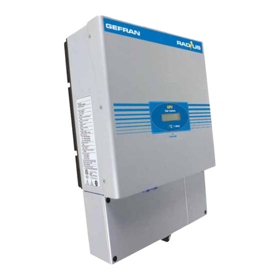
- Page 1 RADIUS Home Single phase solar inverters APV-...-US Solar Inverters ..Installation & operation manual...
- Page 2 Gefran S.p.A has the right to modify products, data and dimensions without notice. The data can only be used for the product description and they can not be understood as legally stated properties.
-
Page 3: Table Of Contents
Contents 1. Notes on this manual ...........................5 Validity................................5 Target Group ..............................5 Safety ................................5 2. APV ...-2M-TL-US Inverter ........................7 Overview ................................7 Identifying model and basic data sheet ......................7 3. Unpacking and inspection ........................8 4. Installation .............................9 Safety instructions / Consignes de sécurité ....................9 Selecting the mounting location ........................10 Mounting the wall mounting frame .......................10 Mounting the inverter on the wall mounting frame .................. - Page 4 RADIUS Home...
-
Page 5: Notes On This Manual
Qualified personnel are trained to deal with the dangers and hazards involved in installing electric devices. Additional information You will find further information on special topics in the download area at www.radius-Gefran.com . 1.3 Safety Appropriate Usage The RADIUS Home - APV is a PV Inverter that converts DC Current from PV generator into AC current. - Page 6 Info Policies vary from one utility company to another. Consult with a representative of the local utility company before proceeding. Les règles peuvent varier d’une entreprise de service public à une autre. Veuillez consulter un représentant de l’entreprise de service public locale avant de concevoir et installer un système PV. DC and AC disconnect switch Separate the RADIUS Home - APV securely from the grid and the PV generators using DC and AC disconnect switch.
-
Page 7: Apv
2.2 Identifying model and basic data sheet You can identify the PV inverter by the type label which is on the left side of the enclosure. Gefran S.p. A - via Carducci,24 - 21040 Gerenzano (VA), Italy APV 1700-2M-TL-US • The type of product (Type/Model). -
Page 8: Unpacking And Inspection
Unpacking and inspection Please check the contents of the shipping box upon receipt. It should contain the following: Item Name Quantity Solar inverter Mounting frame Safety-lock screws Mounting screws Sleeve for mounting frame screws RS485 terminals connection Manuals & software on cd-rom RADIUS Home... -
Page 9: Installation
Installation 4.1 Safety instructions / Consignes de sécurité All electrical installations must be carried out in accordance with the local and national electrical codes ANSI/NFPA 70, NEC. The RADIUS Home - APV inverters are listed to UL1741/IEEE1547 . Do not remove the casing. Inverter contains no user serviceable parts. Refer servicing to qualified service personnel. Warning! Toute installation électrique doit être faite en accord avec les normes électriqueslocales et nationales ANSI/NFPA 70, NEC. -
Page 10: Selecting The Mounting Location
4.2 Selecting the mounting location Raintight or wet location hubs that comply with the requirements of UL 514B for Conduit, Tubing and Cable Fittings must be used. The unit shall be mounted at least 914 mm (3 feet) above the ground. The installation method and mounting location must be suitable for the weight and dimensions of the inverter. -
Page 11: Mounting The Inverter On The Wall Mounting Frame
4.4 Mounting the inverter on the wall mounting frame Hang the inverter on the mounting frame. Insert safety-lock screws through the bottom section of the frame to secure the inverter. 4.5 Checking inverter installation Check the upper straps of PV-Inverter and ensure that it fits on the frame. Check that the PV inverter is mounted securely by trying to raise it from the bottom. The PV-Inverter should remain firmly attached. -
Page 12: Electrical Connection
Electrical Connection All electrical installations must be carried out in accordance with the local and national electrical codes ANSI/NFPA 70, NEC. Warning! Toute installation électrique doit être effectué en accord avec les norms électriques locales et nationales ANSI/NFPA 70, NEC. Policies vary from one utility company to another. Consult with a representative of the local utility company before designing and installing a PV system. Warning! Les règles peuvent varier d’une entreprise de service public à une autre. Veuillez consulter un représentant de l’entreprise de service public locale avant de concevoir et installer un système PV. -
Page 13: Safety
Wire Box 5.2 Safety The PV Inverter must be connected to the AC ground from the grid via the Ground Terminal (PE) Warning! 5.3 Connecting to the grid (AC utility) 5.3.1 GRID standards Before wiring the RADIUS Home - APV-...-US inverter, the installer needs to determine the grid configuration that the inverter will be connected to. The RADIUS Home - APV-...-US inverter is factory-set for a 240 Vac split phase connection. -
Page 14: Connection Of The Ac Wiring (Ac Output)
5.3.2 Connection of the AC wiring (AC output) Determine the correct grid (utility) configuration type, if it is not 240 Vac split phase. You should use the LCD to set the correct net model as detailed in sections 5.3.1 and 6.3. Open the breaker or fuse between PV Inverter and the grid. -
Page 15: Commissioning Checks
Before connecting PV panels to DC terminals, please make sure the polarity is correct . Incorrect polarity could permanently damage the unit. Check short-circuit current of the PV string. The total short-circuit current of the PV string should be less than the inverter’s maximum DC current. Connect the positive and negative terminals from the PV panel to positive (+) terminals and negative (-) terminals on the PV inverter. -
Page 16: Display
Display 6.1 LCD display Starting-up display sequence: once the PV power is sufficient, the inverter displays the following start-up infor- mation: Module: xxxxxx SerNo: xxxxxxxxxx FW Version: x.x.x Connect in: xxS Connect : OK Power: xxxx.xW 6.2 LCD control KNOCK HERE To save power, the LCD display’s backlight automatically turns off after 30 seconds. The inverter display can be controlled by knocking on the front of it. - Page 17 The Second Line Of LCD CYCLE DISPLAY DISPLAY TIME/S REMARK Power 2013.4W Inverter model Module P7U1M2S4 Power 2016.8W Software version Version: U.1.2 Power 2012.8W Serial number SerNO : DK00000000 Power 2009.6W Energy today Etoday 7.1KWh Power 2017.0W Total energy Eall 90KWH Power 2123.4W PV input watt 2123.4W Power 2103.4W...
-
Page 18: Setting The Lcd Display
6.3 Setting the LCD display The LCD can be controlled by knocking on the display to define the display language, contrast, auto-test and frequency. When the LCD is dark Knock to make it becomes bright. The display remain visible for 30 seconds for 1-5 information When the LCD is Bright Knock to make it display next information (all range). Setting the language Knock to make the display bright→... -
Page 19: Operating Modes
Operating modes The inverter has three different operating modes. 7.1 Normal mode In this mode, the inverter works normally. Whenever the supplied power from PV panel is sufficient (voltage>120VDC), the inverter converts power generated by the PV panel to the grid. If the power is insuf- ficient (voltage<120VDC), the inverter enters a “waiting”... -
Page 20: Inverter Status
Inverter status The inverter is designed to be user-friendly; therefore, the status of the inverter can be easily understood by reading the information shown on the front panel display. All possible messages are shown in the following table. System fault DISPLAY OPERATION Auto Test Failed Auto test did not run successfully No AC Connection... -
Page 21: Communications
Communications 9.1 Communications software instructions APV LigthNET is a PC software which communicates with the APV inverter to analyse its operating state. It is a convenient way of determining the inverter’s real-time operating state and operation log. Specification: Communicate with inverter by RS232 and Bluetooth. Construct net with inverter and APV NET via RS232, Bluetooth and the Internet. -
Page 22: 10. Trouble Shooting
10. Trouble shooting In most situations, the Inverter requires very little service. However, if the inverter is not able to function cor- rectly, please refer to the following instructions before contacting your local dealer. Should any problems arise, the LED on the front panel will be red and the LCD will display the relevant informa- tion. -
Page 23: Inverter Failure
10.2 Inverter failure PV Over Voltage Check the open PV voltage to see whether it is greater than or too close to 450Vdc for APV 1700-2M- TL-US or 500Vdc for APV 2300-2M-TL-US and APV 3100-2M-TL-US. If PV voltage is less than 450Vdc for APV 1700-2M-TL-US or 500Vdc for APV 2300-2M-TL-US and APV 3100-2M-TL-US, and the problem still occurs, please contact your local Service Centre. -
Page 24: 11. Specifications
11. Specifications APV 1700-2M-TL-US APV 2300-2M-TL-US APV 3100-2M-TL-US Input Data Max. DC power 1800W 2300W 3150W Max. DC voltage 450V 500V 500V PV voltage range MPPT 120V-400V 120V-450V 120V-450V Initial feeding voltage 150V 150V 150V Max. number of parallel strings Number of MPP trackers Max. - Page 25 APV 1700-2M-TL-US APV 2300-2M-TL-US APV 3100-2M-TL-US Protection Devices Power switch, DC side DC reverse polarity protection PV Ground fault protection Insulation Resistance low protection AC short-circuit protection Grid monitoring Anti islanding protection General Data Dimensions (W / D / H) in mm 360/465/165 360/465/165 360/465/165...
- Page 26 Efficiency Curve Dimensions 165mm [6.5 inches] 360mm [14.17 inches] 465mm [18.3 inches] RADIUS Home...
-
Page 27: 12. Warranty Conditions
12. Warranty conditions The warranty is valid from the date of delivery of the Gefran RADIUS products. The standard manufacturer’s warranty, included in the price of the product, is valid for 5 years starting from the date of delivery. Before the end of that period you may purchase the RWE to extend the manufacturer’s warranty and receive annual cover for between 1 and 5 years. -
Page 28: 13. Contact
13. Contact RADIUS Solar Service (Worlwide) Tel: +39 02 96760428, e-mail: technohelp@gefran.com, fax +39 02 9682653 RADIUS Home... - Page 29 Note: RADIUS Home...
- Page 32 Fax +33 (0) 478770320 Fax +86 21 69169333 info@gefran.be commercial@gefran.fr info@gefransiei.com.cn GEFRAN BRASIL GEFRAN SUISSE SA GEFRAN SIEI Electric (Shanghai) pte. Ltd. ELETROELETRÔNICA Rue Fritz Courvoisier 40 No. 1285, Beihe Road, Jiading District, Avenida Dr. Altino Arantes, 2302 La Chaux-de-Fonds Shanghai, China...
Need help?
Do you have a question about the RADIUS APV 1700-2M-TL-US and is the answer not in the manual?
Questions and answers