
Related Manuals for gefran VDL200 Series


Summary of Contents for gefran VDL200 Series
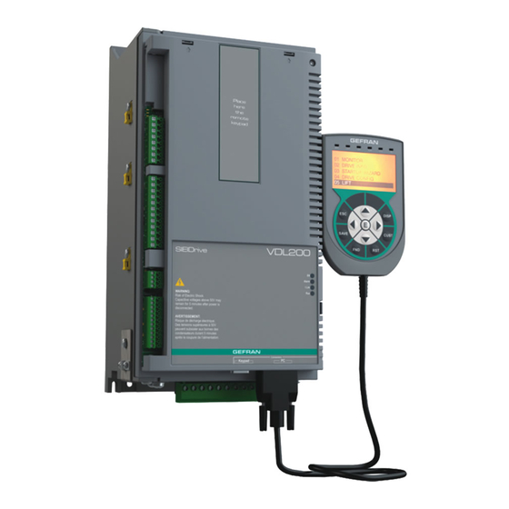
- Page 1 Vector inverter for lifts with asynchronous motors VDL200 ..Quick start up guide Specification and installation...
-
Page 2: Information About This Manual
Gefran S.p.A has the right to modify products, data and dimensions without notice. The data can only be used for the product description and they can not be understood as legally stated properties. -
Page 3: Table Of Contents
Table of Contents Information about this manual ....................... 2 1 - Safety Precautions ........................5 1.1 Symbols used in the manual ............................... 5 1.2 Safety precaution ................................. 5 1.3 General warnings ................................6 1.4 Disclaimer .................................... 6 2 - Introduction to the product ......................7 2.1 Dedicated features ................................ - Page 4 7.4 Serial interface (PC connector) ............................33 7.4.1 Drive/RS232 port point-to-point connection ............................33 7.5 Optional Keypad interface (keypad connector) ......................... 34 7.6 Braking ....................................35 7.6.1 Braking unit (internal) ..................................35 8. Use of the keypad ........................36 8.1 Description of KB-ADL optional programming keypad ...................... 36 8.1.1 Membrane keypad ....................................36 8.1.2 Meaning of LEDs ....................................36 8.2 Navigating with the optional keypad ..........................
-
Page 5: Safety Precautions
Use for intended purpose only The power drive system (electrical drive + application plant) may be used only for the application stated in the manual and only together with devices and components recommended and authorized by Gefran. Utiliser uniquement dans les conditions prévues Le système d’actionnement électrique (drive électrique + installation) ne peut être utilisé... -
Page 6: General Warnings
your electrical drive and the plant you connect to it. Lire attentivement les informations en matière de sécurité personnelle et visant par ailleurs à prolonger la durée de vie utile du drive tout comme de l’installation à laquelle il est relié. 1.3 General warnings This equipment contains dangerous voltages and controls potentially dangerous rotating mechanical parts. -
Page 7: Introduction To The Product
2 - Introduction to the product The SIEIDrive VDL200 is the result of GEFRAN’s experience in the civil lift engineering sector, gained from its commitment to working in close partnership with leading operators in the sector to develop technical solutions and application programs. -
Page 8: Other Features
• Saving parameters Drive parameters can be saved on the keypad (5 settings). • Integrated encoder management 5 V TTL incremental digital encoder. 2.2 Other features • Autotuning of motor parameters. • SSC (Sensorless Scalar Control) modulation reduces noise levels to a minimum. •... -
Page 9: Identification Of Components
2.3 Identification of components The inverter converts the constant frequency and voltage of an existing three-phase network into DC voltage, from which it obtains a new three-phase network with variable voltage and frequency. With this variable three-phase network the speed of three-phase asynchronous motors can be controlled continuously. 1. -
Page 10: Product Identification
Mechanical dimensions of the drive: 1 = size 1 3 = size 3 2 = size 2 Inverter, VDL200 series Data plate Type = Drive model; S/N = Serial number Inp = Input (mains supply, frequency, AC Input Current at constant torque) -
Page 11: Transport And Storage
3 - Transport and storage Correct transport, storage, erection and mounting, as well as careful operation and maintenance are essential for proper and safe operation of the equipment. Protect the inverter against physical shocks and vibration during transport and storage. Also be sure to protect it Caution against water (rainfall) and excessive temperatures. -
Page 12: Specification
4 - Specification 4.1 Environmental Conditions Installation location �������������������� Pollution degree 2 or lower (free from direct sunligth, vibration, dust, corrosive or inflammable gases, fog, vapour oil and dripped water, avoid saline environment) Installation altitude �������������������� Max 2000m (6562 feet) above sea level. With 1.2% reduction in output current for every 100 m starting from 1000 m. -
Page 13: Input Electrical Data
4.4 Input electrical data Choke ������������������������������� Sizes 1...2: Optional (DC or AC). Note! See chapter 5.2 for THD values in accordance with EN 12015 and for selection of external inductances. Input Input DC-Link Overvoltage Undervoltage voltage Effective input current I (@ In out) frequency Capacity... -
Page 14: Derating Values For Switching Frequency
4.5.2 Derating values for switching frequency The switching frequency is modified according to the temperature of the drive (measured on the heat sink), as shown in the figure below. Figure 4.5.2: Ratio between switching frequency/heat sink temperature (kHz) T diss (°C) T diss th 4.5.3 Kalt: Ambient temperature reduction factor Figure 4.5.3: Tamb reduction coefficient... -
Page 15: Cooling
4.8 Cooling All inverters are equipped with internal fans. Size Fan capacity Minimum cabinet opening for (Heat dissipation) cooling =230...400V Heat sink (m Internal (m VDL200-...-4, 3ph 1040 1055 2 x 58 2075 2 x 58 2110 2 x 35 3150 2 x 98 3185... -
Page 16: Weights And Dimensions
4.9 Weights and dimensions Figure 4.9.1: Size 1 dimensions 148.1 Dimensions: Width x Height x Depth Weight Sizes (mm) (inches) (kg) (lbs) VDL200-1040-...-4 162 x 343 x 159 6.38 x 13.50 x 6,26 12.3 VDL200-1055-...-4 Figure 4.9.2: Size 2 dimensions 148.1 Dimensions: Width x Height x Depth Weight... - Page 17 Figure 4.9.3: Size 3 dimensions 218.3 Dimensions: Width x Height x Depth Weight Sizes (mm) (inches) (kg) (lbs) VDL200-3150-...-4 VDL200-3185-...-4 235 x 456.5 x 180 9,25 x 17.97 x 7.08 10.5 23.15 VDL200-3220-...-4 VDL200 • Quick installation guide - Specifications and connection...
-
Page 18: Options
5 - Options 5.1 Optional external fuses 5.1.1 Network side fuses (F1) The inverter must be fused upstream on the network side. Use fast-acting fuses only. F1 - External network side fuses EUROPE AMERICA DC link capacitor hours of Size service life [h] Type Code... -
Page 19: Ac Output Chokes
5.3 AC output chokes The VDL200 inverter can be used with standard motors or motors designed specifically for use with inverters. The latter usually have a higher isolation rating to better withstand PWM voltage Examples of reference regulations are provided below: motors designed for use with inverters do not require any specific filtering of output from the inverter. -
Page 20: Emc Filter (Optional)
5.5 EMC Filter (optional) The VDL200-...-F-4 inverters are equipped with an internal EMI filter, optional external filters are reported in the table. Dimensions: Weight Conducted emissions according to / Motor Size Type Code W x H x d (mm) (kg) cable length VDL200-... -
Page 21: Mechanical Installation
6 - Mechanical installation The Drive must be mounted on a wall that is constructed of heat resistant material. While the Drive is operating, the temperature of the Drive’s cooling fins can rise to a temperature of 158° F (70°C). Le drive doit être monté... -
Page 22: Fastening Positions
6.2 Fastening positions Fissaggio a muro • Wall mounting • Fixation mural • Wandmontagee • Fijación en pared 23.5 (5.53) (0.93) 23.5 (0.93) (5.53) 33.5 (1.32) (6.61) Taglia 1 Taglia 2 Taglia 3 Size 1 Size 2 Size 3 Grandeur 1 Grandeur 2 Grandeur 3 Größe 1... -
Page 23: Wiring Procedure
7 - Wiring Procedure Adjustable frequency drives are electrical apparatus for use in industrial installations. Parts of the Drives are energized during operation. The electrical installation and the opening of the device should therefore only be carried out by qualified personnel. Improper installation of motors or Drives may therefore cause the failure of the device as Warning! well as serious injury to persons or material damage. -
Page 24: Power Section
Functioning of the Drive without a ground connection is not permitted. To avoid disturbances, the armature of the motor must be grounded using a separate ground connector from those of other appliances. Caution Défense de faire fonctionner le drive sans qu’il y ait eu raccordement de mise à la terre préalable. Pour éviter les perturbations, la carcasse du moteur doit être mise à... -
Page 25: Connection Of Shielding (Recommended)
Use Power shield kit to connect shield of motor cable to drive. Note! For further information regarding electro-magnetic compatibility standards, according to Directive 2014/30/EU, conformity checks carried out on Gefran appliances, connection of filters and mains inductors, shielding of cables, ground connections, etc., consult the “Electro-magnetic compatibility guide” on the CD attached to this drive. -
Page 26: Block Diagram Of Power Section
7.1.4 Block diagram of power section This type is equipped with an EMI input filter (models VDL200-...-F), an AC/DC converter, a system for pre-loading DC capacitors, a DC/AC converter, a power supply unit and an integrated braking unit. To manage emergency situations (drive power failure) the unit also envisages connection of an emergency unit between terminals EM and D. -
Page 27: Motor Connection
7.1.8 Motor connection L1 L2 L3 BR C1 C V W EM 3 ph 7.1.9 Connection of braking resistor (optional) L1 L2 L3 BR C1 C V W EM Braking resistor Note! Recommended combination braking resistors: see paragraph 5.4. VDL200 • Quick installation guide - Specifications and connection... -
Page 28: Regulation Section
7.2 Regulation section Figure 7.2.1: Identification of cards and terminals VDL200 Asynchronous (R-VDL200 card) PC/GF_eXpress RS232 (D-SUB 9F) Keypad R-VDL200 RS422 (D-SUB 9F / RJ45-8) 7.2.1 Cable cross-sections Maximum cable cross-section Recommended stripping Tightening torque (min) Terminals (AWG) (mm) (Nm) 0,2 ... -
Page 29: Feedback Connection
Figure 7.2.4: Recommended card wiring 7.2.3 Feedback Connection This section describes the feedback connections for the VDL200 asynchronous: 1) Connection digital encoder 3 Channels, TTL Line Driver / Push pull(DE) 2) Repeat Encoder (TTL line-driver) Figure 7.2.5: Connection of shielding (recommended) 1) Connection digital encoder 3 Channels, TTL Line Driver / Push pull (DE) Note ! The encoder power supply must be adequate considering the cable length and the absorption rates as shown in paragraph "7.2.4 Internal power supply of the... - Page 30 Figure 7.2.7: Connection Incremental digital encoder (DE), Single Ended PNP O.C./ NPN O.C 0VE out 0VE out +VE out +VE out (*) Connection of shielding, see figure 7.2.4 2) Repeat Encoder (TTL line-driver) Encoder expansion cards have an incremental encoder output with TTL/HTL Line Driver levels (according to the main encoder supply) to be used to repeat the servomotor feedback device.
-
Page 31: Connection Diagrams
7.3 Connection diagrams Note! This chapter describes the typical wiring diagrams with reference to VDL200 drives with standard configuration. 7.3.1 Regulation potentials, digital I/O Figure 7.3.1.1: Regulation potentials (VDL200) Shielded cable Analog input 1 Relay 1 Shield Relay 2 +24V HW Enable Relay 3 Digital input 1... -
Page 32: Emergency Connection Diagram
7.3.3 Emergency connection diagram The configuration described in this paragraph can be used to manage the motor in an emergency power failure condition (with 230 VAC single-phase UPS power supply or EMS module). Figure 7.3.3.1: Emergency connection diagram 3 PHASE MAINS 1ph, 230V 50Hz (optional) -
Page 33: Serial Interface (Pc Connector)
7.4 Serial interface (PC connector) Funzione / Function Interfaccia elettr./ Elect. Interface PIN 1 – – PIN 2 RS232 PIN 3 RS232 PIN 4 – – PIN 5 0V (Ground) – Alimentazione / Supply PIN 6 – – PIN 7 –... -
Page 34: Optional Keypad Interface (Keypad Connector)
Connection to a PC with RS232 port (not isolated) The following are required for connection: • a shielded cable (cod. 8S864C L=4.5mt; cod. 8S874C L=10mt) for connection to the RS232 PC port of the drive to the RS232 connector of the PC, see figure 7.4.1-B. Connection to a PC with USB port (not isolated) The following are required for connection: •... -
Page 35: Braking
7.6 Braking There are various possible types of braking: Internal Braking Unit Injection of direct current from the Inverter into the motor (D.C. braking) There are two essential differences between the two braking methods: A braking unit can be used for speed reduction (e.g.: from 1000 to 800 rpm), whereas D.C. braking can only be usedfor braking to standstill. -
Page 36: Use Of The Keypad
8. Use of the keypad This chapter describes the optional KB-ADL keypad and methods of use for displaying and programming inverter parameters. 8.1 Description of KB-ADL optional programming keypad → Drive status indicator LEDs ILim 01 MONITOR ← 02 DRIVE INFO 03 STARTUP WIZARD 04 DRIVE CONFIG 5-line x 21 character alphanumerical LCD display... -
Page 37: Navigating With The Optional Keypad
8.2 Navigating with the optional keypad 8.2.1 Scanning of the first and second level menus First level 23 ALARM LOG 01 MONITOR 01 MONITOR 02 DRIVE INFO 02 DRIVE INFO 03 STARTUP WIZARD 03 STARTUP WIZARD 04 DRIVE CONFIG 04 DRIVE CONFIG 05 LIFT 01 MONITOR... -
Page 38: Scanning Of The Parameters
8.2.3 Scanning of the parameters 01 MONITOR 01 MONITOR 01 MONITOR 02 DRIVE INFO 01/20 PAR: 20/20 PAR: 1400 Di g ital output X mon 03 STARTUP WIZARD Output current 00000000010001 04 DRIVE CONFIG 05 LIFT 01 MONITOR 02/20 PAR: ... -
Page 39: How To Save Parameters
LINK parameters ● The parameter may assume the number of another parameter as value. 11 DIGITAL OUTPUTS 11 DIGITAL OUTPUTS 11 DIGITAL OUTPUTS 11 DIGITAL OUTPUTS 14 MOTOR DATA 01/16 PAR: 1410 01/16 PAR: 1410 01/16 PAR: 1410 15 ENCODER CONFIG Di g output 1X s r c Di g output 1X s r c... -
Page 40: Configuration Of The Display
8.2.8 Configuration of the display 8.2.8.1 Language selection Menu 04 DRIVE CONFIG, parameter 04.19 Language select, PAR: 578, default=English. This is used to set one of the languages available: English, Italian, French, German, Spanish and Turkish. 01 MONITOR 04 DRIVE CONFIG 04 DRIVE CONFIG 04 DRIVE CONFIG 02 DRIVE INFO... -
Page 41: Messages
8.2.12 Messages Operator messages are displayed with this page. There are two types of messages: - timed (closed automatically after a certain number of seconds), - permanent (continue to be displayed until the operator presses the ESC key). Several concurrent messages are enqueued and presented to the operator in sequence, starting from the most recent. Message Default parameters 0001H-1... -
Page 42: Load Parameters From Keypad
If an error occurs during transfer, the following message is displayed: Message Save par failed Code: Press ESC to exit The code XX indicates the type of error, see paragraph 10.3. To exit the error message, press the ESC key. 8.2.13.3 Load parameters from keypad Menu 04 DRIVE CONFIG, parameter 04.15 Load par from keypad, PAR: 592. -
Page 43: Commissioning Via Keypad
9 - Commissioning via keypad Adjustable frequency drives are electrical apparatus for use in industrial installations. Parts of the Drives are energized during operation. The electrical installation and the opening of the device should therefore only be carried out by qualified personnel. Improper installation of motors or Drives may therefore cause the failure of the device as well as serious injury to persons or material Warning! damage. - Page 44 This equipment must not be used as an ‘emergency stop mechanism’ (see EN 60204, 9.2.5.4). Ne pas utiliser cet appareil en tant que « dispositif d’arrêt d’urgence » (cf. EN 60204, 9.2.5.4). Never open the device or covers while the AC Input power supplyis switched on. Minimum time to wait before working on the terminals or inside the device is listed in section 4.6.
-
Page 45: Asynchronous Motor Startup Wizard (With The Optional Keypad)
9.1 Asynchronous motor startup wizard (with the optional keypad) The VDL200 can operate with regulation modes: Voltage/Frequency (SSC) , Sensorless (open loop) and field-oriented vector control (closed loop). Note! Before starting, check the factory settings: Menu 04 DRIVE CONFIG, parameter 04.2 Regulation mode, PAR: 552, default=SSC control. 01 MONITOR 04 DRIVE CONFIG 02 DRIVE INFO... - Page 46 Step 1 - Electrical connections Make the connections as described in paragraph 7.3.2. Checks to be performed before powering the drive • Check that the supply voltage is correct and that the input terminals on the drive (L1, L2 and L3) are connected correctly.
- Page 47 Note! When data entry is complete the Take parameters command is executed automatically (menu 14 MOTOR DATA, PAR: 2020). The motor data entered during the STARTUP WIZARD procedure are saved in a RAM memory to enable the drive to perform the necessary calculations. These data are lost if the device is switched off.
- Page 48 ▲ 5.3 A PAR: 2102 PAR: 2102 Encoder supply Encoder supply ▼ 0000005.2 5.1 A Def: Def: Step 5 – Encoder phasing Not available in this mode. Step 6 - Setting the maximum speed reference value and system speed Setting the maximum speed reference value: this defines the maximum motor speed value (in rpm) that can be reached with each single reference signal (analog or digital).
- Page 49 ▲ 1 kgm² PAR: 11160 PAR: 11160 Motor inertia Motor inertia ▼ 000000000 kgm² 0 kgm² kgm² Def: Def: After setting the mechanical measurements, proceed to the next step. Step 8 - Setting application parameters The application data can be entered at this stage. ●...
- Page 50 Set the ramp values ● ▲ 0.6 m/s³ PAR: 11040 PAR: 11040 Acc start jerk Acc start jerk ▼ 00000000.5 m/s³ 0.4 m/s³ m/s³ Def: Def: ▲ 0.7 m/s² PAR: 11042 PAR: 11042 Acceleration Acceleration ▼ 00000000.6 m/s² 0.5 m/s²...
- Page 51 Step 9 - Save parameters To save the new parameter settings, so that they are maintained also after power-off, proceed as follows: 03 STARTUP WIZARD 03 STARTUP WIZARD PAR: 550 PAR: 550 End of se q uence Save parameters? Save parameters? Save parameters? Press E to exe c ute Do n e...
-
Page 52: Troubleshooting
10 - Troubleshooting 10.1 Alarms Note ! To reset alarms, see paragraph "8.2.11 Alarms". In the following table, the Code is visible only from serial line Code Error message shown Sub-code Description on the display No alarm Condition: No alarm present Condition: DC link overvoltage alarm due to energy recovered from the motor. - Page 53 Code Error message shown Sub-code Description on the display Solution: - Reduce the motor load. - Increase the size of the motor. Condition: Braking resistor overload alarm. The current absorbed by the resistor is greater than the rated current. Bres overload [BOL] Solution: - Check the size of the braking resistor.
- Page 54 Solution: Contact Gefran in order to update the firmware on the optional encoder card. Condition: an optional card has been removed with respect to the configuration present when the last Save parameters command was executed or there Opt cfg change [OCFG] is a fault on the optional card or on the regulation card.
-
Page 55: Speed Fbk Loss Alarm According To The Type Of Feedback
When this has been signalled the information obtained from the encoder is not reliable. Solution: Contact Gefran in order to update the firmware on the optional card. If an error occurs during the setup phase, "Encoder error" is displayed with subcode 0x0100 - 256 (Setup error). -
Page 56: Messages
10.3 Messages Note ! For more information see paragraph "8.2.12 Messages". Index Error message shown on Sub-code Description the display Condition: may occur during loading of the parameter database saved in flash normally appears in the following conditions: at initial power-on when a new firmware version is downloaded, when the regulation is installed on a new Load default param [LDEF] size, when the region is changed. - Page 57 Index Error message shown on Sub-code Description the display Solution: Download the correct configuration on the power card Save par failed Condition: during transfer of the parameters from the drive to the memory of the keypado [FAIL] 0H-0 Communication error 0023H-35 Communication error 0023H-36...
- Page 58 [KEYF] Solution: Ask Gefran to supply the correct key to enable the desired firmware function. Condition: this may occur at drive power-on if the incorrect enabling key was inserted for a given firmware function. At this stage the firmware function...
-
Page 59: Appendix
Appendix A.1 - I/O Specification The I/O integrated in the R-VDL200 regulation card are: 1 enable input (Enable) + 8 digital inputs (DI) + 4 relay outputs (RO) + 1 analog input (AI). VDL200 (Asynchronous) SH SH AI 50 51 52 53 54 55 56 57 10 11 99 99 42 43... - Page 60 Analog inputs (AI) ● Description Features Type Voltage differential Input voltage ± 10 V (± 12.5 V full scale) Input R 10 kΩ Resolution 12 Bits (11 + sign) Precision 1% of full scale Isolation Description Features Type Current differential Input current 0 (4) mA to 20 mA Input R...
-
Page 61: Encoders And Phasing
A.2 Encoders and Phasing A.2.1 Encoders Encoders provide motor speed and position feedback The regulation algorithms in the VDL200 drive are capable of controlling asynchronous motors and may or may not use the speed measurement obtained from the encoder reading. Possible configurations are summarised in the table: Asynchronous VDL200... -
Page 62: Phasing
A.2.2 Phasing In order for the VDL200 Brushless regulation algorithm to function correctly, it is necessary to know the position of the rotor with respect to the stator power phases. Therefore the 0° position provided by the absolute encoder must be known with respect to the position of a motor pole and the encoder count direction must match the motor power phases. -
Page 63: Brake Monitoring System (A3 Amendment)
A.3 - Brake monitoring system (A3 Amendment) A.3.1 Introduction The brake monitoring function in the VDL200 series enables implementation of the automatic brake monitoring function as required by EN81-1 A.3 §9.11.3. Two functional elements are required to implement the brake monitoring function: 1. -
Page 64: Configuration Of The Brake Fault Alarm
A.3.2 Configuration of the brake fault alarm • Activation of the brake fault alarm function. The installer must have previously located the necessary digital inputs of the VDL200 drive and connected the cor- responding wires to the feedback signals on these inputs. Note that depending on the type of wiring arrangement, the brake feedback signals are normally asserted (brake closed –... - Page 66 Fax +55 (0) 1132974012 commercial@gefran.fr comercial@gefran.com.br GEFRAN S.P.A. Manuale VDL200 ASY QS -EN GEFRAN DRIVES AND MOTION S.R.L. Via Sebina 74 Rev. 1.0 - 18-1-2022 25050 Provaglio d’Iseo (BS) ITALY Via Carducci 24 Ph. +39 030 98881 21040 Gerenzano [VA] ITALY...
Need help?
Do you have a question about the VDL200 Series and is the answer not in the manual?
Questions and answers