
Related Manuals for gefran AGy-EV Series


Summary of Contents for gefran AGy-EV Series
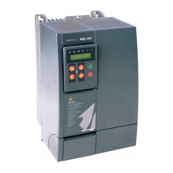
- Page 1 General-Purpose Inverter 230/400/460V Class 575V Class AGy -EV ..Instruction Manual...
- Page 2 Keep the manual in a safe place and available to engineering and installation personnel during the product functioning period. Gefran S.p.A has the right to modify products, data and dimensions without notice. The data can only be used for the product description and they can not be understood as legally stated properties.
-
Page 3: Table Of Contents
Table of Contents Safety Symbol Legend - Precautions de securité ..............6 Chapter 1 - Safety Precautions ....................7 1.1 Power Supply and Grounding ..............................10 Chapter 2 - General........................11 Features ......................................12 Accessories / Options ..................................12 Chapter 3 - Inspection Procedure, Component Identification and Standard Specification ..13 3.1 Upon Delivery Inspection Procedures ............................ - Page 4 5.7.3 Interference Suppression Filters .............................. 50 5.7.3.1 EMI filter connections for Sizes 1007...3150 (230V...480V) ................... 52 5.7.3.2 EMI filter connections for Sizes 4185...82000 (230V...480V) ..................53 5.8 Braking in the AGy System ................................ 54 5.8.1 Braking Unit ..................................... 54 5.8.1.1 External Braking Resistor ............................... 56 5.8.2 D.C.
- Page 5 Ramp Configuration ..................................141 Jump Frequencies ................................... 143 7.6 Menu P - PARAMETERS ................................145 Commands ...................................... 145 Control Mode ....................................150 Power Supply ....................................151 Motor Data ..................................... 151 V/F Curve ......................................152 Ouput Frequency Limit ..................................154 Slip Compensation ..................................154 Boost ......................................
-
Page 6: Safety Symbol Legend - Precautions De Securité
8.1.3.1 The address .................................. 197 8.1.3.2 The function code ................................. 197 8.1.3.3 CRC16 ................................... 198 8.1.3.4 Message synchronization ............................. 198 8.1.3.5 Serial line setting ................................198 8.1.4 Modbus functions for the drive .............................. 199 8.1.4.1 Read Output Registers (03) ............................199 8.1.4.2 Read Input Registers (04) ............................. -
Page 7: Chapter 1 - Safety Precautions
Chapter 1 - Safety Precautions According to the EEC standards the AGy-EV and accessories must be used only after checking that the machine has been produced using those safety devices required by the 89/392/EEC set of rules, as far as the machine industry is concerned. These standards do not apply in the Americas, but may need to be considered in equipment being shipped to Europe. - Page 8 ou de drives peuvent provoquer des dommages materiels ou blesser des personnes.On doit suivir les instructions donneés dans ce manuel et observer les régles nationales de sécurité. Always connect the Drive to the protective ground (PE) via the marked connection terminals (PE2) and the housing (PE1).
- Page 9 If the Drive’s Fault Alarm is activated, consult the TROUBLESHOOTING section of this instruction book, and after correcting the problem, resume operation. Do not reset the alarm automatically by external sequence, etc. Si la Fault Alarm du drive est activée, consulter la section du manuel concernant les défauts et après avoir corrigé...
-
Page 10: Power Supply And Grounding
1) GEFRAN drives are designed to be powered from standard three phase lines that are electrically symmetrical with respect to ground (TN or TT network). Les variateurs GEFRAN sont prévus pour être alimentés par un réseau triphasé équilibré avec un régime de neutre standard (TN ou TT). -
Page 11: Chapter 2 - General
Chapter 2 - General SieiDrive - AGy-EV is an AC Digital Inverters for the variation of the speed of three-phase motors. The AGy can be supplied with a power range from 0.75kW up to 200kW (230V...480V) and from 2Hp up to 200Hp (575V). An intermediate voltage is generated from the rectified AC voltage. -
Page 12: Features
Features Supply voltages generated by switching starting from the intermediate circuit voltage. Reduction of motor noise is achieved by the use of a special PWM control procedure. The output of the Inverter is protected against short circuits and earth faults. Motors can be switched on and off at the Inverter output (see chapter 5.2.4 of the manual). -
Page 13: Chapter 3 - Inspection Procedure, Component Identification And Standard Specification
Chapter 3 - Inspection Procedure, Component Identification and Standard Specification 3.1 Upon Delivery Inspection Procedures 3.1.1 General A high degree of care is taken in packing the AGy Drives and preparing them for delivery. They should only be transported with suitable transport equipment (see weight data). Observe the instructions printed on the packaging. This also applies when the device is unpacked and installed in the control cabinet. -
Page 14: Nameplate
3.1.3 Nameplate Check that all the data stated in the nameplate enclosed to the inverter correspond to what has been ordered. Figure 3.1.3.1: Identification Nameplate (example for 575V series) Type : AGyEV- 3010 -KBX-5 S/N: 03062492 Inp: 575Vac 50/60Hz 3Ph 15A @575 Vac With line Choke Out : 0-575Vac 400Hz 3Ph 10Hp @ 575Vac 13,3A @575V Cont. -
Page 15: Component Identification
3.2 Component Identification Figure 3.2.1: Basic Setup of Frequency Inverter An AGy Drive converts the constant voltage and frequency of a three-phase power supply into a direct voltage and then converts this direct voltage into a new three-phase power supply with a variable voltage and frequency. This variable three- phase power supply can be used for the infinitely variable adjustment of the speed of three-phase asynchronous motors. -
Page 16: Standard Specifications
3.3 Standard Specifications 3.3.1 Permissible Environmental Conditions Table 3.3.1.1: Environmental Specification E N V I R O N M E N T [°C] 0 … +40; +40…+50 with derating Ambient temperature [°F] 32 … +104; +104…+122 with derating Pollution degree 2 or better (free from direct sunligth, vibration, dust, corrosive or inflammable gases, fog, Installation location vapour oil and dripped water, avoid saline environment) Up to 1000m (3281 feet) above sea level;... -
Page 17: Disposal Of The Device
Disposal of the Device The AGy Drive can be disposed as electronic scraps in accordance with the currently valid national regulations for the disposal of electronic parts. The plastic covering of the Drives are recyclable: the material used is >ABS+PC< . 3.3.2 Mains Connection and Inverter Output The AGy Drive must be connected to an AC mains supply capable of delivering a symmetrical short circuit current lower or equal to the values indicated on table 3.3.2.1. - Page 18 Table 3.3.2.1-A: AC Input/Output Specifications for 230V...480V Drive Kw/Hp Rating *: For the specified power sizes, the external reactor is strongly recommended **: Linear shapes for K , respectively in the ranges [400, 460] Vac, [40, 50]°C, (104, 122)°F. Example: for AC mains = 440VAC, 400V/440V = 0.90 = K 18 •...
- Page 19 Table 3.3.2.1-B: AC Input/Output Specifications for 575V Drive Hp Rating AGy-EV Instruction manual Chapter 3 Inspection Procedure, Component Identification and Standard Specification • 19...
-
Page 20: Ac Input Current
3.3.3 AC Input Current The Input current of the Drive depends on the operating state of the connected motor. The tables 3.3.2.1 shows the values corresponding to rated continuous service, keeping into account typical output power factor for each size 3.3.4 AC Output The output of the AGy Drive is ground fault and phase to phase output short protected. -
Page 21: Open-Loop And Closed-Loop Control Section
3.3.5 Open-Loop and Closed-Loop Control Section No. 3 Analog inputs 3 Programmable Analog inputs: . Analog input 1 ±10 V 0.5 mA max, 10 bit + sign / unipolar or bipolar (0...10V=default) . Analog input 2 ±10 V 0.5 mA max, 10 bit + sign / unipolar or bipolar (±10 V =default) . - Page 22 22 • Chapter 3 Inspection Procedure, Component Identification and Standard Specification AGy-EV Instruction manual...
-
Page 23: Chapter 4 - Installation Guidelines
Chapter 4 - Installation Guidelines 4.1 Mechanical Specification Figure 4.1.1: AGy Dimensions for Sizes 1007...3150 (230V...480V) and 2002... 3020 (575V) Table 4.1.1: AGy Dimensions and Weights for Sizes 1007...3150 (230V...480V) and 2002... 3020 (575V) Drive dimensions: mm (inch) Weight Type kg (lbs) 1007 3.5 (7.7) - Page 24 Figure 4.1.2: AGy Mounting Methods for Sizes 1007...3150 (230V...480V) and 2002... 3020 (575V) E2 E4 Mounting with external dissipator (E) Mounting wall (D) Table 4.1.2: AGy Mounting Methods for Sizes 1007...3150 (230V...480V) and 2002... 3020 (575V) Drive dimensions: mm (inch) Type Ø...
- Page 25 Figure 4.1.3 : AGy Dimensions for Sizes 4185...82000 (230V...480V) and 4025... 8200 (575V) Figure 4.1.4 : AGy Mounting Methods for Sizes 4185...82000 (230V...480V) and 4025... 8200 (575V) Mounting wall (D) Table 4.1.3 : AGy Dimensions and Weights for Sizes 4185...82000 (230V...480V) and 4025... 8200 (575V) Drive dimensions: mm (inch) Weight Type...
- Page 26 Figure 4.1.5: Keypad Positioning To allow a confortable viewing angle, the keypad can be oriented on three different positions. 26 • Chapter 4 - Installation Guidelines AGy-EV Instruction manual...
-
Page 27: Watts Loss, Heat Dissipation, Internal Fans And Minimum Cabinet Opening Suggested For The Cooling
4.2 Watts Loss, Heat Dissipation, Internal Fans and Minimum Cabinet Opening Suggested for the Cooling The heat dissipation of the Drives depends on the operating state of the connected motor. The table below shows values that refer to operation at default switching frequency (see section 3.3.4, “AC Output”), Tamb < 40°C (104°F), typ. motor power factor and nominal continuous current. -
Page 28: Cooling Fans Power Supply
4.2.1 Cooling Fans Power Supply Sizes 1007...5550 (230V...480V) and 2002... 5075 (575V) Power supply (+24Vac) for these fans are provided from the internal drive power supply unit. Sizes 6750 ... 82000 (230V...480V) and 6100 ... 8200 (575V) Power supply for these fans have to be provided as follow: - 6750 (230V...480V) and 6100 (575V): 0.8A@115V/60Hz, 0.45A@230V / 50Hz - 7900 ... -
Page 29: Installation Mounting Clearance
4.3 Installation Mounting Clearance The dimensions and weights specifed in this manual should be taken into consideration when the device is mounted. The technical equipment required (carriage or crane for large weights) should be used. Improper handling and the use of unsuitable tools may cause damage. Figure 4.3.1: Max. -
Page 30: Motors And Encoder
4.4 Motors and Encoder The AGy Drives are designed for open-loop and closed-loop operation of standard three-phase induction AC motors. 4.4.1 AC Induction Motors FOR BEST RESULTS: Select a inverter duty single cage induction motor with a minimum slip of 3-5%. a) Minumum motor size: motor amps no less than 30% of drive rated amps at 400 VAC continuous rating b) General purpose motors can be used but require additional AC output chokes c) Inverter duty motors are desirable and do not require output chokes... -
Page 31: Encoder
Motor protection Temperature-dependent contacts in the motor winding Temperature-dependent contacts “Klixon” type can disconnect the drive via the external control or can be reported as an external fault on the frequency inverter (terminal 6). The motor PTC interface circuit (or klixon) has to be considered and treated as a signal circuit. The connections cables to the motor PTC must be made of twisted pairs with a shield, the cable route should not be parallel to the motor cable or far away at least 20 cm (8 inches). - Page 32 32 • Chapter 4 - Installation Guidelines AGy-EV Instruction manual...
-
Page 33: Chapter 5 - Wiring Procedure
Chapter 5 - Wiring Procedure 5.1 Accessing to the Connectors Observe the safety instructions and warnings given in this manual. The devices can be opened without the use of force. Only use the tools specified. Figure 5.1.1: AGy Removing Covers for Sizes 1007...3150 (230V...480V) and 2002...3020 (575V) No. - Page 34 Figure 5.1.2: AGy Removing Covers for Sizes 4185...82000 (230V...480V) and 4025...8200 (575V) Sizes 4185...82000 (230V...480V) and 4025...8200 (575V) The terminal cover of the device must be removed in order to fit the electrical connections: unscrew the two screw (2) and remove the cover (1).
-
Page 35: Power Section
5.2 Power Section Table 5.2.1.1: Power Section Terminals for Sizes 1007...3150 (230V...480V) and 2002...3020 (575V) Function U1/L1 230V -15%…480V +10% 3Ph~ V1/L2 AC mains voltage or 575 V ±10% See table 3.3.2.1 W1/L3 Braking unit resistor command (braking resistor must be connected between BR1 and C) 770 Vdc (230...480 Vac) Braking resistor... -
Page 36: Maximum Cable Cross Section For Power Terminals
5.2.1 Maximum Cable Cross Section for Power Terminals AC input wiring is connected to a disconnected switch, which limits the size to the following ranges: AGy...-4 (230V...400V) Type 1007 1015 1022 1030 2040 2055 2075 3110 3150 4185 4220 4300 U1,V1,W1,U2,V2,W2,C,D terminals [mm2]... -
Page 37: Rectification And Intermediate (D.c.) Circuit
5.2.2 Rectification and Intermediate (D.C.) Circuit The mains voltage is rectified and buffered by capacitors. A diode bridge with a pre-charging resistor is mounted for all sizes. In the event of an overvoltage in the intermediate circuit (message “OV” appears in the display) or undervoltage (message “UV”), the Inverter blocks and no power can be taken from the intermediate circuit. -
Page 38: Inverter
5.2.3 Inverter IGBTs (Insulated Gate Bipolar Transistors) for all sizes are used. The Inverter is protected against faults of overvoltage, overcurrent, short circuit between phases and ground. In the event of a fault the Inverter is disabled and the contact between terminals 2 and 3 will open. -
Page 39: Regulation Section
5.3 Regulation Section 5.3.1 R-AGy Regulation Card Figure 5.3.1.1: R-AGy Regulation Card Table 5.3.1.1: LEDs, Jumpers and Connectors on R-AGy-2 Color Function LED turns on when the voltage + 5V is present green and at correct level RS 485 yellow LED turns on when Serial interface is supplied Connector No. -
Page 40: Terminal Assignments On Regulation Section
5.3.2 Terminal Assignments on Regulation Section Function Designation Strip 1 Digital Output 4 - NO 1A 30Vdc Programmable digital relay output - Default: [1] Alarm state Digital Output 4 - COM 1A 250Vac Digital Output 4 - NC Digital Input 8 Programmable digital input - Default: [2] Reverse Programmable digital input - Default:... -
Page 41: Serial Interface
Figure 5.4.1.1: RS485 Serial Interface The RS 485 on the AGy-EV series devices is located on the Regulation card in the form of a 9-pole SUB-D socket connector (XS). The communication may be with or without galvanic isolation: when using galvanic isolation an external power supply is necessary (+5V). -
Page 42: Rs 485 Serial Interface Connector Description
Serial protocol The serial protocol is set via the “I.600 - Serial link cfg” parameter, which allows the selection of the following types: proprietary protocol FoxLink, RTU Modbus (default) and Jbus. The serial address is set via the “I.602 - Device address” parameter. Further details about the parameter transmission, the parameter type and the value range can be found in the tables of Chapter 7.1 (INTERFACE Menu / Serial Configuration). -
Page 43: Typical Connection Diagrams
5.5 Typical Connection Diagrams 5.5.1 AGy Connection Figure 5.5.1.1: Connection through Terminals Strip, Typical Connection Diagram BRAKING RESISTOR 230/400/460V 3-phase 575V 3-phase U1/L1 U2/T1 FILTER V1/L2 V2/T2 W1/L3 W2/T3 + 24V OUT Dig Output 4 - NO Reverse Dig Input 8 Digl Output 4 - NC Allarm state Dig Input 7... -
Page 44: Engineering Notes
Figure 5.5.1.2: Other Connections REVERSAL EXT FAULT Stop (3wires) RESET CM-IN CM-IN CM-IN GND-D GND-D Connections for NPN-type Controls Connections for Controls Opto-insulated from the Inverter ( NPN ) Connections for Controls Opto-insulated from the Inverter ( PNP ) 5.5.2 Engineering Notes Cables for analog reference and correction values should be screened (connection to the following terminals 25, 26, 27, 28, 29, 30). -
Page 45: Parallel Connection On The Ac (Input) And Dc (Intermediate Circuit) Side Of Several Inverters
5.5.3. Parallel Connection on the AC (Input) and DC (Intermediate Circuit) Side of Several Inverters Features and Limits: The inverters used have to be all the same size. AC input line chokes (see chapter 5.7.1) have to be the same (provided by the same supplier). The mains power supply has to be simultaneous for all inverters, i.e. -
Page 46: Circuit Protection
5.6 Circuit Protection 5.6.1 External Fuses of the Power Section The inverter must be fused on the AC Input side. Use fast fuses only. Connections with three-phase inductance on AC input will improve the DC link capacitors life time. Table 5.6.1.1: External Fuse Types for AC Input Side F1 - Fuses type (Code) DC link capacitors life time Drive type... -
Page 47: External Fuses Of The Power Section Dc Input Side
The technical data of the fuses, e.g. dimensions, weights, heat dissipation, auxiliary contactors, are reported in the corresponding data sheets. 5.6.2 External Fuses of the Power Section DC Input Side Use the following fuses when a SR-32 Line Regen converter is used (see SR-32 instruction book for other details). Table 5.6.2.1: External Fuses Type for DC Input Side Europe America... -
Page 48: Internal Fuses
AGy series Drives. The inductance can be provided by an AC Input choke or an AC Input transformer. For the use of output sinusoidal filters, please contact the nearest GEFRAN office. Figure 5.7.1: Input / output chokes dimensions 48 •... -
Page 49: Ac Input Chokes
5.7.1 AC Input Chokes Table 5.7.1.1: 3-Phase AC Input Chokes Three-phases main chokes Mains Rated Saturation Freq. Drive type Dimensions : mm (inch) Weight inductance current current Model Code kg (lbs) [mH] [Hz] 1007 50/60 LR3y-1007 S7AAD 1.8 (3.9) 1015 3.69 50/60 LR3y-1015 S7AAE... -
Page 50: Interference Suppression Filters
In the Guide it is also indicated how to install the cabinet (connection of filter and mains reactors, cable shield, groundig, etc.) in order to make it EMC compliant according the EMC Directive 89/336/EEC. The document describes the present situation concerning the EMC standards and the compliance tests made on the GEFRAN- SIEI drives. - Page 51 Table 5.7.3.1: EMI filters Dimensions : mm (inch) Weight EN 61800- Drive type Model Code 3:2004 kg (lbs) 1007…3110 EMI-C 480-25 S7DFA 0.96 (2.1) 105 (4.1) 100 (3.9) 57 (2.2) 51 (2.0) 95 (3.7) 4.5x3 150 (5.9) 1007…82000 ECF3 S4ZZ2 1.2 (2.7) 120 (4.72) 110 (4.33)
-
Page 52: Emi Filter Connections For Sizes 1007
5.7.3.1 EMI filter connections for Sizes 1007...3150 (230V...480V) AC Mains AC Drive Cabinet Mounting panel AC fuses Contactor Power Supply Mains choke U1 V1 W1 U2 V2 W2 PE2 PE1 EMI filter Output reactor Motor cable Ground terminals AC Motor 52 •... -
Page 53: Emi Filter Connections For Sizes 4185
5.7.3.2 EMI filter connections for Sizes 4185...82000 (230V...480V) Inverter Cabinet Mounting panel Supply Line reactor U2, V2, W2 PE U, V, W EMI-FN filter Output reactor Motor cable Ground terminals Motor AGy-EV Instruction manual Chapter 5 - Wiring Procedure • 53... -
Page 54: Braking In The Agy System
5.8 Braking in the AGy System Two means of braking are possible: Internal Braking Unit Injection of direct current from the Inverter into the motor (D.C. braking) There are two essential differences between the two braking methods: A braking unit can be used for speed reduction (e.g.: from 1000 to 800 rpm), whereas D.C. braking can only be used for braking to standstill. - Page 55 Table 5.8.1.1: Braking Thresholds for Different Mains Mains voltage Braking threshold 220 Vac 390 Vdc 380 Vac 760 Vdc 460 Vac 760 Vdc 575 Vac 965 Vdc agy0705 Table 5.8.1.2: Technical Data of the Internal Braking Units Inverter Minimum type [ohm] 1007 …...
-
Page 56: External Braking Resistor
5.8.1.1 External Braking Resistor Recommended resistors for use with internal braking unit: Table 5.8.1.3: Lists and Technical Data of the External Standard Resistors [kJ] Drive Resistor Dimensions : mm (inch) Weight Code kg (lbs) Type [Ohm] Type 1007 ... 1015 RF 220 T 100R S8T0CE 0.5 (1.1) - Page 57 T = 2 = [s] Figure 5.8.3: Limit Operating Braking Cycle with Typical Triangular Power Profile Minimum cycle time in condition of limit operating cycle (braking power = P with typical triangular profile) = [s] Resistor model: Standard resistor data Example code: RFPD 900 DT 68R RFPD = resistor type...
- Page 58 =[w] PB R [ohm] Where: = braking unit threshold (see table 5.8.1.1) With reference to the figure 5.8.5, where the power profile is the typical triangular one, the following example can be taken into consideration (see also table 5.8.1.3). Resistor model: MRI/T600 100R Nominal power P = 600 [W] Maximum energy E...
-
Page 59: Braking
5.8.2 D.C. Braking The Inverter offers the facility of D.C. braking as a standard. To this end, the Inverter injects D.C. current into two motor phases, thereby generating braking torque. The kinetic energy of the machine is dissipated as heat in the motor. This option enables the drive to be braked to a standstill. -
Page 60: Chapter 6 - Drive Keypad Operation
Chapter 6 - Drive Keypad Operation In this chapter the parameters management is described, by using the drive keypad. The following examples show some procedures with the two different keypads, KBG-1 (7 segments display) and KBG- EV-LCD (alphanumeric LCD display). The procedures of parameters setting will be the same for both keypad types. The displaying of parameters will be different, in accordance with the keypad model mounted on the drive. -
Page 61: Language Selection
Keypad LED’s meaning: (Yellow LED): flashes if the parameters have not been permanently saved to memory. (Green LED): reverse running (*) (Green LED): forward running (*) (Red LEDs): Indicates the unit of measurement of the parameter currently displayed (**). Hz,A,V Green LEDs blinking denote the action of the motor stall prevention. -
Page 62: Moving Through The Drive Main Menu
and the RS485 kit (protected cable with connectors and PCI485 for connection using the RS485series line: cod. S5QQ1 1) Install the E@syDrives program and connect the computer series port to the XS connector of the drive. 2) Power on the drive. 3) Follow the instructions of the E@syDrives program and begin a “Working Session”... -
Page 63: Scrolling Through The Drive Parameters
6.5 Scrolling Through the Drive Parameters INTERFACE menu example: INTERFACE I000 - - - - - - - - - - - - - - INTERFACE I001 - - - - - - - - - - - - - - INTERFACE I002 - - - - - - - - - - - - - -... -
Page 64: Quickstart Procedure
6.7 Quickstart procedure Basic settings for trial run Goto menu S – Startup, and proceed to step 2. Set the drive input mains voltage Edit parameter S.000 to set the nominal voltage of input mains (ex. 220V, 400V, 460V, 575V). Goto step 3. Set the drive input mains frequency Edit parameter S.001 to set the nominal frequency of input mains (50Hz or 60Hz). - Page 65 Set the drive maximum allowed By default, the reference frequency is limited to the frequency reference frequency of the input mains. If the application requires higher settings of the motor reference frequency, increase the value of parameter S.201. Goto step 10. Select the source of drive main By default, the drive frequency reference is the value written frequency reference.
-
Page 66: Advanced Settings
Measure the resistance of stator windings If the resistance of stator windings is known, its ohmic value can be entered in parameter S.153, and the autotuning procedure can be skipped. Otherwise, execute the autotuning command (S.900 = [1]) and wait for the procedure to end. -
Page 67: Chapter 7 - Parameter Description
Chapter 7 - Parameter Description 7.1 Parameters List Legend of drive menu contents. Menu d - DISPLAY Menu of read-only parameters (display) Menu S - STARTUP Menu for basic drive start up Menu I - INTERFACE Menu of input/output settings (digital/analog, serial, etc.) Menu F - FREQ &... - Page 68 Figure 7.1: Parameters Description Legend : Parameter Code, showed on display. Format = X.YYY: X = Menu d=DISPLAY S=STARTUP I=INTERFACE F=FREQ & RAMPS P=PARAMETER A=APPLICATION C=COMMAND H=HIDDEN YYY = Parameter number : Parameter name, ]: P DISPLAY IST CODE IN BRAKET showed on display LCD S ELECTION...
- Page 69 PARAMETER PICK LIST DISPLAY ESCRIPTION ESCRIPTION LCD S ELECTION DISPLAY d.000 Output frequency Drive output frequency 0.01 d.001 Frequency ref Drive frequency reference 0.01 d.002 Output current Drive output current (rms) d.003 Output voltage Drive output voltage (rms) d.004 DC link voltage DC Bus drive voltage (DC) d.005 Power factor...
- Page 70 PARAMETER PICK LIST DISPLAY ESCRIPTION ESCRIPTION LCD S ELECTION d.171 Exp DrvDigOutSta Expansion digital outputs status, commanded by DO functions Expansion virtual digital d.172 Exp vir dig sta out outputs status, commanded via serial link or field bus card d.200 An in 1 cnf mon [0] Null funct Analog input 1 destination;...
- Page 71 PARAMETER PICK LIST DISPLAY ESCRIPTION ESCRIPTION LCD S ELECTION d.351 Option 2 state Drive option 2 state As for d.350 (expansion board type programmed) d.353 SBI State Communication state Wait parametrization between SBI and Master Wait configuration Data exchange Error d.354 SBI Baudrate Communication speed...
- Page 72 PARAMETER PICK LIST DISPLAY ESCRIPTION ESCRIPTION LCD S ELECTION 45kW - 230/400/460V 55kW - 230/400/460V 75kW - 230/400/460V 90kW - 230/400/460 110kW - 230/400/460V 132kW - 230/400/460V 160kW - 230/400/460V 18.5kW - 230/400/460V 200kW - 230/400/460V 2.0Hp - 575V 3.0Hp - 575V 5.0Hp - 575V 7.5Hp - 575V 10Hp - 575V...
- Page 73 PARAMETER PICK LIST DISPLAY ESCRIPTION ESCRIPTION LCD S ELECTION START-UP S.000 Mains voltage Rated value of the line 230V, only for AGy-4 (****) (****) (****) voltage 380V, only for AGy-4 (P.020) 400V, only for AGy-4 420V, only for AGy-4 440V, only for AGy-4 460V, only for AGy-4 480V, only for AGy-4 500V, only for AGy-5...
- Page 74 PARAMETER PICK LIST DISPLAY ESCRIPTION ESCRIPTION LCD S ELECTION S.400 Manual boost [%] Manual boost at low 25.0 % of revolutions S.100 (P.120) S.401 Auto boost en Automatic boost function [0] Disable Automatic boost function enabling disabled (P.122) [1] Enable Automatic boost function enabled S.450...
- Page 75 PARAMETER PICK LIST DISPLAY ESCRIPTION ESCRIPTION LCD S ELECTION INTERFACE I.000 Dig input 1 cfg Digital Input 1 configuration [0] None Not active [1] Run RUN command for the motor START [2] Reverse Speed REVERSE command [3] Ext Fault NO External fault with NO (Normal Open) contact [4] Ext Fault NC...
- Page 76 PARAMETER PICK LIST DISPLAY ESCRIPTION ESCRIPTION LCD S ELECTION I.006 Dig input 7 cfg Digital Input 7 configuration As for I.000 I.007 Dig input 8 cfg Digital Input 8 configuration As for I.000 I.050 Exp dig in 1 cfg Expansion Digital Input 1 As for I.000 configuration (on Expansion board)
- Page 77 PARAMETER PICK LIST DISPLAY ESCRIPTION ESCRIPTION LCD S ELECTION [11] DC-link lim DC Bus limit. [12] Limit active General signalling of drive limit condition. [13] Autocapt run Autocapture in progress. [14] BU overload Set when the integrator d.054 = 100%, and Reset when d.054 = 0% [15] Neg pwrfact Negative inverter output...
- Page 78 PARAMETER PICK LIST DISPLAY ESCRIPTION ESCRIPTION LCD S ELECTION [43] CoastThrough Kinetic energy recovering during mains loss [44]EmgStop Emergency stop after mains loss detection [45] DC braking CD braking in progress [46] Drv OL status Set when the integrator d.051 = 100%, and Reset when d.051 = 0% [47] Drv OL warn Set if d.051 is greater or...
- Page 79 PARAMETER PICK LIST DISPLAY ESCRIPTION ESCRIPTION LCD S ELECTION I.200 An in 1 Type Setting of the Analog Input [0] ± 10V Bipolar ± 10V 1 type reference (voltage) [1] 0-10V/0-20mA Unipolar +10V I.201 An in 1 offset Analog Input 1 offset -99.9 99.9 I.202...
- Page 80 PARAMETER PICK LIST DISPLAY ESCRIPTION ESCRIPTION LCD S ELECTION [19] U current Output phase U current signal. [20] V current Output phase V current signal. [21] W current Output phase W current signal. [22] Freq ref fac Multiplier factor for frequency reference I.301 An out 1 offset...
- Page 81 PARAMETER PICK LIST DISPLAY ESCRIPTION ESCRIPTION LCD S ELECTION I.600 Serial link cfg Serial line configuration [0] FoxLink 7E1 FoxLink 7E1 7 Even 1 protocol & mode [1] FoxLink 701 FoxLink 7O1 7 Odd 1 [2] FoxLink 7N2 FoxLink 7N2 7 None 2 [3] FoxLink 8N1 FoxLink 7O1 8 None 1 [4] ModBus 8N1...
- Page 82 PARAMETER PICK LIST DISPLAY ESCRIPTION ESCRIPTION LCD S ELECTION I.762 SBI to Drv W 2 Word 2 from SBI to drive 1999 I.763 SBI to Drv W 3 Word 3 from SBI to drive 1999 I.764 SBI to Drv W 4 Word 4 from SBI to drive 1999 I.765...
- Page 83 PARAMETER PICK LIST DISPLAY ESCRIPTION ESCRIPTION LCD S ELECTION FREQ & RAMP F.000 Motorpot ref Motopot reference (it can F.020 0.01 be set using up and down commands) F.010 Mp acc/dec time Motorpot Accel. and Decel. 999.9 ramp time F.011 Motorpot offset Motopotentiometer F.020...
- Page 84 PARAMETER PICK LIST DISPLAY ESCRIPTION ESCRIPTION LCD S ELECTION F.103 Frequency ref 3 Digital Reference frequency 3 -F.020 F.020 F.104 Frequency ref 4 Digital Reference frequency 4 -F.020 F.020 F.105 Frequency ref 5 Digital Reference frequency 5 -F.020 F.020 F.106 Frequency ref 6 Digital Reference frequency 6 -F.020...
- Page 85 PARAMETER PICK LIST DISPLAY ESCRIPTION ESCRIPTION LCD S ELECTION PARAMETER P.000 Cmd source sel It defines the use of START [0] Keypad START & STOP via and STOP commands keypad (+24V between 5 & 8 terminals required). [1] Terminals START & STOP via terminal [2] Virtual Main commands via...
- Page 86 PARAMETER PICK LIST DISPLAY ESCRIPTION ESCRIPTION LCD S ELECTION V/F curve defined by the P.060 V/f shape V/F Curve Type [0] Custom user Linear characteristic [1] Linear Quadratic characteristic [2] Quadratic P.061 Max out voltage Maximum output voltage (**) (**) P.062 Base frequency Base frequency...
- Page 87 PARAMETER PICK LIST DISPLAY ESCRIPTION ESCRIPTION LCD S ELECTION P.180 SW clamp enable Current clamp enable [0] Disable [1] Enable P.181 Clamp alm HldOff Hold off time for the current 25.5 25.5 clamp alarm P.200 Ramp Currlim Mode Enable current limitation [0] None None during ramp...
- Page 88 PARAMETER PICK LIST DISPLAY ESCRIPTION ESCRIPTION LCD S ELECTION P.280 BU Config Braking unit configuration [0] BU disabled BU disabled [1] BU en OL dis BU enabled & Overload disable [2] BU en OL en BU & Overload enabled P.281 Brake res value Ohmic value of braking resistor...
- Page 89 PARAMETER PICK LIST DISPLAY ESCRIPTION ESCRIPTION LCD S ELECTION P.380 Autoreset attmps Number of autoreset attempts P.381 Autoreset clear En. automatic reset of autorestart attempts P.382 Autoreset delay Autoreset time delay P.383 Autores flt rly Alarm relay contacts [0] OFF behaviour during autoreset [1] ON P.400...
- Page 90 PARAMETER PICK LIST DISPLAY ESCRIPTION ESCRIPTION LCD S ELECTION °C P.480 Heatsnk temp lev Heatsink temperature signalling level °C P.481 Heatsnk temp hys Hysteresis band related to P.480 P.500 Switching freq Modulation frequency [0] 1kHz P.502 [1] 2kHz [2] 3kHz [3] 4kHz [4] 6kHz [5] 8kHz...
- Page 91 PARAMETER PICK LIST DISPLAY ESCRIPTION ESCRIPTION LCD S ELECTION APPLICATION A.000 PID mode PID mode [0] Disable Null 1200 [1] Freq sum PID out in sum with ramp out ref (Feed forward) [2] Freq direct PID out not in sum with ramp out ref (no Feed forward) [3] Volt sum...
- Page 92 PARAMETER PICK LIST DISPLAY ESCRIPTION ESCRIPTION LCD S ELECTION A.300 AND1 In 1 src Set up input block AND1 As for I.100 1355 A.301 AND1 In 2 src Set up input block AND1 As for I.100 1356 A.302 AND2 In 1 src Set up input block AND2 As for I.100 1357...
- Page 93 PARAMETER PICK LIST DISPLAY ESCRIPTION ESCRIPTION LCD S ELECTION COMMAND C.000 Save parameters Save parameters command No action. Save parameters command. C.001 Recall param Recall last set of saved No action. parameters Recall last set of saved parameters. C.002 Load default Recall of the factory No action.
- Page 94 PARAMETER PICK LIST ESCRIPTION ESCRIPTION LCD S ELECTION HIDDEN This menu is not available on the keypad. The setting and the reading of the parameters here contained, can be performed exclusively via serial line or through SBI card. H.000 Virtual digital command 1000 H.001 Exp virtual digital command...
- Page 95 PARAMETER PICK LIST ESCRIPTION ESCRIPTION LCD S ELECTION H.100 Remote Digital Inputs (0..15) 65535 1021 H.101 Remote Digital Inputs (16..31) 65535 1022 H.110 Remote Digital Outputs (0..15) 65535 1023 H.111 Remote Digital Outputs (16..31) 65535 1024 H.120 Remote Analog input 1 -32768 32767 1025...
-
Page 96: Menu D - Display
7.2 Menu d - DISPLAY Basic d.000 Output frequency Drive output frequency [Hz]. d.001 Frequency ref (Frequency reference) Drive frequency reference [Hz] . d.002 Output current Drive output current (rms) [A]. d.003 Output voltage Drive output voltage (rms) [V]. d.004 DC link voltage Drive DC Bus voltage (DC) [V]. -
Page 97: Overload
Overload d.050 Heatsink temp (Heatsink temperature) Drive heatsink temperature [°C]. d.051 Drive OL (Drive overload level) The drive overload control function is based on a I t, that allows for the IEC 146 class 2 service. The I t integrator level can be read in d.051, and is calculated as follows: ∫... -
Page 98: Inputs/Outputs
d.052 Motor OL (Motor overload) Motor overload level (100% = alarm threshold). d.053 Brake res OL (Brake resistror overload) Braking resistor overload level (100%=alarm thr). d.054 Reserved Code LCD display [Code] & LCD select. Default Unit Variation d.050 Heatsink temp °C d.051 Drive OL... - Page 99 d.120 Exp dig inp stat (Expansion board digital inputs status) Status of the expansion digital inputs acquired by the drive. Each of the inputs can come either from regulation board terminal , from optional field bus card or from serial line. See figure 7.4.8 . According to the type of keypad in use, the status of expansion digital inputs will be displayed as follows: I.
- Page 100 d.170 Exp dig out sta (Expansion board digital outputs status) Status of the expansion digital outputs terminals of the regulation board. Each output can be set by the associated drive function (see I.150, ..., I.152) or by writing the parameter H.010 (see figure 7.4.9). According to the type of keypad in use, the status of expansion digital outputs will be displayed as follows: Exp Dig out stat Exp Digital output 2 = ON...
-
Page 101: Encoder
d.211 An in 2 monitor (Analog input 2 monitor) Analog input 2 - block output (%). See figure 7.4.1. d.212 An in 2 term mon (Analog input 2 terminals monitor) Analog input 2 - block input (%). See Fig. 7.4.1. It monitors the signal at the An In 2 regulation board terminals, according to the value of An inp 2 Type (I.210) parameter: •... -
Page 102: Pid
d.302 Encoder speed Speed detected by the encoder (d.000 * P.600). Code LCD display [Code] & LCD select. Default Unit Variation d.300 EncPulses/Sample 0.001 d.301 Encoder freq 0.01 d.302 Encoder speed 0.01 / 1 Option d.350 Option 1 state It monitors the status of the optional board 1. d.351 Option 2 state It monitors the status of the optional board 2. -
Page 103: Alarm List
SW version (2/2) (Software version - part 2) Display example: 00.00 00 = index of revision (fixing bugs) 00 = index of identification (special version) to be considered as reference for Gefran personell d.953 Power ident code (Power identification code) Reserved. AGy-EV Instruction manual... -
Page 104: Utility
d.954 Param ident code (Parameters identification code) Reserved. d.955 Regul ident code (Regulation identification code) Reserved. d.956 Startup id code (Startup identification code) Reserved. d.957 Drive size Drive size code. d.958 Drive cfg type Drive configuration type: 0 = 400Vac/50Hz, 1 = 460 or 575Vac / 60Hz. Code LCD display [Code] &... -
Page 105: Menu S - Start-Up
7.3 Menu S - START-UP The START UP menu is a set of parameters and functions that allows a quick start of the motor.These parameters are actually links to a selection of parameters present in other menus. Therefore, avy modification on a parameter in the START-UP menu is also reflected on the linked parameter found on a different menu, and vice-versa. -
Page 106: Motor Data
Motor Data S.150 Motor rated curr (Motor rated current) (linked to P.040) Rated current of the motor at rated kilowatt/horsepower and voltage (given on the nameplate, see figure7.3.2). In case of control with multiple motors, enter a value equal to the sum of the rated currents of all the motors. Do not perform any self tune. -
Page 107: Commands & Referencies
Commands & Referencies S.200 Cmd source sel (Command source selection) (linked to P.000) It defines the source of the main commands (START and STOP) and auxiliary commands (REVERSE, ENABLE, DC-BRAKE, etc.). S.200 = 0 START & STOP via keypad, auxliliary commands via digital input terminals. In this configuration, START and STOP commands are given through the keypad buttons. - Page 108 S.201 Max ref freq (Maximum reference frequency) (linked to F.020) It is the maximum allowed value for the frequency reference (absolute value), which ever the source. (See figure 7.5.1). S.202 Ref 1 Channel (Reference 1 channel) (linked to F.050) It defines the source of the frequency reference 1. By default, the frequency reference is supplied through the parameter S.203.
-
Page 109: Functions
Functions S.400 Manual boost [%] (linked to P.120) The resistive impedance of the stator windings causes a voltage drop within the motor, which results in a reduction of torque in the lower speed range. Compensation can be made for this effect by boosting the output voltage. S.100 S.400 P .064... -
Page 110: Utility
S.451 Slip comp filter (Slip compensation filter) (linked to P.101) It is the response time (in seconds) of the slip compensation function. The lower the setting of this parameter, the quicker will be the response od slip compensation. However, setting too low may give rise to undesired oscillations of the speed after sudden load variations. -
Page 111: Menu I - Interface
7.4 Menu I - INTERFACE Digital Inputs Regulation Board I.000 Dig input 1 cfg (Digital input 1 configuration) I.001 Dig input 2 cfg (Digital input 2 configuration) I.002 Dig input 3 cfg (Digital input 3 configuration) I.003 Dig input 4 cfg (Digital input 4 configuration) I.004 Dig input 5 cfg (Digital input 5 configuration) I.005 Dig input 6 cfg (Digital input 6 configuration) I.006 Dig input 7 cfg (Digital input 7 configuration) -
Page 112: Digital Inputs Expansion Board
Motorpot Dn Motorpotentiometer reference decreasing command. See paragraph 7.5, Motorpotentiometer section. Reset Motorp Reset of Motorpotentiometer reference. See paragraph 7.5, Motorpotentiometer section. Fast stop Emergency stop command (with ramp time F.206). See paragraph 7.5 . Zero freq Output frequency forced to zero, following the ramp programmed for Fast stop (F.206). -
Page 113: Programmable Logic Output
Programmable Logic Output I.070 AND 1 out cfg (AND 1 block output configuration) I.071 AND 2 out cfg (AND 2 block output configuration) I.072 AND 3 out cfg (AND 3 block output configuration) I.073 OR 1 out cfg (OR1 block output configuration) I.074 OR 2 out cfg (OR 2 block output configuration) I.075 OR 3 out cfg (OR 3 block output configuration) I.076 NOT 1 out cfg (NOT 1 block output configuration) - Page 114 REV rotation Counter-clockwise rotation of the motor Steady state Motor is running in steady state Ramping Acceleration or Deceleration Ramp in progress UV running The drive has tripped for UV, and automatic restart is taking place. Out trq>thr Output torque higher than the value of P.241 Current lim Current limit (during ramp or at steady state) DC-link lim...
-
Page 115: Digital Outputs Expansion Board
Exp DI 1 Digital input 1 expansion state Exp DI 2 Digital input 2 expansion state Exp DI 3 Digital input 3 expansion state Exp DI 4 Digital input 4 expansion state AND 1 out Output block AND 1 state AND 2 out Output block AND 2 state AND 3 out... -
Page 116: Analog Inputs Regulation Board
Analog Inputs Regulation Board The figure below describes the block diagram of the standard "Analog Inputs" of the drive. Figure 7.4.1: Analog Inputs 116 • Chapter 7 - Parameters Description AGy-EV Instruction manual... - Page 117 The regulation board provides as standard 3 analog inputs. Analog inputs resolution: voltage input setting: 11 bits (10 bits + sign) current input setting: 10 bits A typical connection is reported in figure 5.5.1.1. Each analog input can be programmed to execute any of the functions below: [1] Freq ref 1 Frequency reference 1 chapter FREQ &...
- Page 118 Gain of the analog input. It is used to amplify or to attenuate the analog signal at the related terminal. I.203 An In 1 minimum (Analog Input 1 minimun) I.213 An In 2 minimum (Analog Input 2 minimun) I.223 An In 3 minimum (Analog Input 3 minimun) It defines the minimum value of the output of the related analog input block (see figure 7.4.3).
- Page 119 100 - I.203 An Inp Drive [%] = I.203 + x I.202 x An Inp Terminal [%] + I.201 AnInp Drive I.202=2 100% I.202=1 I.203=50% -100% -10V AnInp Terminal 100% - I.203 -100% Figure 7.4.4:Analog input characteristic with minimum value, offset and gain (bipolar) When the analog input reference is set to 0V, an eventual "noise"...
-
Page 120: Analog Outputs Regulation Board
Code LCD display [Code] & LCD select. Default Unit Variation I.200 An in 1 Type [0] ±10V [1] 0...10V / 0...20mA I.201 An in 1 offset -99.9 99.9 I.202 An in 1 gain -9.99 9.99 0.01 I.203 An in 1 minimum 99.99 0.01 I.204... - Page 121 I.300 Analog out 1 cfg (Analog output 1 configuration) I.310 Analog out 2 cfg (Analog output 2 configuration) Each output is programmable with a specific code and function, as shown in the list below. ANALOG OUTPUTS SELECTION LIST: Code LCD display Description Freq out abs Output Frequency, absolute value...
- Page 122 I.303 An out 1 filter (Analog output 1 filter) I.313 An out 2 filter (Analog output 2 filter) It is the time costant of the digital filtering performed on the related Analog output. See fig.7.4.6. By using the above described parameters, it is possible to customize the input/output characteristic of each Analog output block, as shown below.
-
Page 123: Analog Outputs Exp Board
The table below shows the analog outputs scaling. CODE Variable Full scale value (±10V) Freq out abs F.020 x P.080/100 [Hz] (Maximum output frequency) Freq out Same as CODE 0 Output curr 2 x D.950 [Arms] (2 x Inverter rated current) Out voltage P.061 [Vrms] (Maximum output voltage) Out trq pos... -
Page 124: Enabling Virtual I/O
Enabling Virtual I/O By using "virtual I/O", it is possible to mix digital inputs actually coming from terminals of the regulation board with a string of virtual digital inputs directly controlled via serial line or fieldbus. Likewise, it is possible to control some of the drive digital and analog outputs directly from serial line or fieldbus. It is possible to configure the drive so that some commands come from digital input terminals of the regulation board (terminal digital inputs), while others come from serial line or fieldbus, by writing the dedicated parameters H.000 and H.001 (virtual digital inputs). - Page 125 VIRTUAL DIGITAL OUTPUTS CONFIGURATION Selection logics for digital output is described by the following figure: Drive logical states I.103 ... I.100 Virtual settings H.010 d.151 d.152 Mask I.420 Bit 0 Bit 3 Bit 2 Bit 1 d.150 Mask bits = 0 Þ...
- Page 126 VIRTUAL ANALOG OUTPUTS CONFIGURATION Analog outputs at the terminals of the regulation board are normally written by the drive, according to the settings of parameters I.300, I.310, I.320. However, it is possible to control the analog outputs directly from serial line or fieldbus, by writing parameters H.020, H.021, H.022 .
- Page 127 DIGITAL OUTPUTS Programming example for: • ALARM STATE signalling on Digital output 1 • VIRTUAL SETTING on Digital output 2 I.420 = 2 bit 1 is high (1) and bit 0 is low (0) I.100 = 1 ALARM STATE (programmed on digital output 1) I.101 = X ANY SELECTION (programmed on digital output 2) Digital output 1...
- Page 128 I.400 Inp by serial en Bitwise mask parameter for virtual digital input. The state of each one of the bits in this mask determines if the corresponding digital input function of the drive (programmed by I.000 ... I.007) has to be associed to the virtual digital input or to the terminal digital input.
-
Page 129: Encoder Configuration
Mask: Bit 0 = 1 Virtual analog output 1 enabling Bit 1 = 1 Virtual analog output 2 enabling = 16 Bit 4 = 1 Virtual expansion analog output 1 enabling Code Name Selection Default Unit Variation I.400 Inp by serial en I.410 Exp in by ser en I.420... -
Page 130: Serial Configuration
are related as follows: n [rpm] x P .041 [polepairs] F [rpm] x 60[s] [Hz] = n [rpm] = P .041 [polepair] 60[s] Where: Motor electrical frequency detected by the encoder. Motor mechanical speed. Encoder sampling time, defined by the parameter I.504. Number of encoder pulses counted by the drive in the interval (displayed as d.300) puls... - Page 131 I.601 Serial link bps (Serial link bit per second) It defines the Baud rate (bit per second) of the serial communication. Possible selections are shown on the table at the end of the paragraph. I.602 Device address Address at which the drive can be accessed if it is networked via the RS485 interface. The range of the selectable addresses is between 0 and 99.
-
Page 132: Options Configuration
Options Configuration I.700 Option 1 type [0] Board Off None [1] Board master Reserved [2] IO Board EXP-D6-A1R1-AGy (Optionals I/O card, code: S524L) [3] Board free Reserved [4] SBI Board SBI-PDP-AGy (Profibus-DP card, code: S5H28) I.701 Option 2 type [0] Board Off None [1] Board master Reserved... -
Page 133: Sbi Configuration
SBI Configuration In this menu it is possible to perform the configuration of the SBI card. Detailed information about the filedbus interfacing, is reported in the specific instruction manuals of the SBI cards. I.750 SBI Address Setting of the different addresses of the slaves connected to the bus. I.751 CAN baudrate CAN Open or DeviceNet baudrate. - Page 134 I.771 Drv to SBI W 1 (Drive to SBI Word 1) I.772 Drv to SBI W 2 (Drive to SBI Word 2) I.773 Drv to SBI W 3 (Drive to SBI Word 3) I.774 Drv to SBI W 4 (Drive to SBI Word 4) I.775 Drv to SBI W 5 (Drive to SBI Word 5) Sbi to Drive Wx = Word exchanged from Sbi to Drive Drive to Sbi Wx = Word exchanged from Drive to Sbi...
-
Page 135: Menu F - Freq & Ramps
7.5 Menu F - FREQ & RAMPS The diagram below, describes the logic for the "Reference selection". Dig input = Multi freq sel Dig input = Multi freq sel Dig input = Multi freq sel Dig input = Multi freq sel Figure 7.5.1: Reference Selection Motorpotentiometer F.000 Motorpot ref (Motorpotentiometer reference) - Page 136 The Motorpotentiometer reference can also be changed via digital inputs, programmed as Motorpot up and Motorpot down (see par. 7.4, I.000). It is possible to reset the Motorpotentiometer via a digital input programmed as Reset Motorpot. The Motorpotentiometer is reset if the motor is not in “Run” (see par. 7.4, I.000). F.010 Mp acc/dec time (Motorpotentiometer Acceleration / Deceleration time) It sets the acceleration and deceleration ramp time (in seconds), for the Motorpotentiometer function.
-
Page 137: Reference Limits
Reference Limits F.020 Max ref freq (Maximum reference frequency) Defines the maximum value (absolute value) allowed for the frequency reference. This parameter applies to the sum of the two references available on the drive (Reference 1 and Reference 2). F.021 Min ref freq (Mimimum reference frequency) It defines the minimum frequency value, under which any regulation with analog or digital references has no effect. -
Page 138: Reference Sources
Reference Sources F.050 Ref 1 Channel (Reference 1 channel) F.051 Ref 2 Channel (Reference 2 channel) As shown in figure 7.5.1, the source of each of the two frequency referencies can be independently selected. Available selections are reported in the table at the end of this paragraph. The effective frequency reference for the drive will always be the algebric sum of the two channels. -
Page 139: Multispeed Function
[6] Analog inp 3 (setting through I.220…I.224) [7] Encoder (setting through I.500…I.505) [8] Profidrive Reference by Profibus F.060 MltFrq channel 1 As for F.050, Ref 1 channel F.061 MltFrq channel 2 As for F.051, Ref 2 channel F.080 FreqRef fac src [0] Null [1] Analog inp 1 (setting through I.200…I.204) - Page 140 The following figure shows the setting of a 8 Multispeed control. Freq Selectable through “MltFreq Channel 1” (F.060) “MltFreq Channel 2“ (F.061) Freq ref 3 Freq ref 4 Freq ref 2 Freq ref 5 Freq ref 1 Freq ref 6 Freq ref 0 Freq ref 7 Freq sel 1...
-
Page 141: Ramp Configuration
Ramp Configuration During normal drive operation, a ramp generator is used to ramp the drive output frequency up or down to a programmed setpoint. It is possible to temporarily freeze the ramp generator output, by using a digital input programmed as "Ramp enabled" (DI_Ramp Enable = 0), see 7.4 paragraph, I.000. - Page 142 F.205 Acc time 3 (Acceleration time 3) F.206 Dec time 3 / FS (Deceleration time 3) F.207 Acc time 4 (Acceleration time 4) F.208 Dec time 4 (Deceleration time 4) Ramp acceleration and deceleration times are used to avoid abrupt changes in the inverter output frequency that may cause mechanical shocks, excessive motor current and excessive DC-bus voltage.
-
Page 143: Jump Frequencies
F.250 Ramp S-shape The S-shaped ramp can be used to obtain a smooth behaviour of the system at the beginning and at the end of the acceleration and deceleration. The ramp time, intended as the time needed for accelerating from zero to the maximum frequency F.020, is given by the sum of the linear ramp time in use and the S-shape time F.250. - Page 144 Freq Reference Out F.270 F.270 F.272 F.271, F272 F.270 F.270 F.271 Freq Reference In Figure 7.5.7: Jump Frequencies When the frequency reference is set to a value within the forbidden band, the frequency output assumes the following behavior. Example: Increasing the reference from values lower than F.271 F.271 = 30Hz (first forbidden frequency threshold) F.270 = 1Hz (forbidden band: 29Hz….31Hz) Setting of frequency reference = 29,5Hz...
-
Page 145: Menu P - Parameters
7.6 Menu P - PARAMETERS Commands Figure 7.6.1: Basic Commands Logic Selection AGy-EV Instruction manual Chapter 7 - Parameters Description • 145... - Page 146 Figure 7.6.2: Main Commands Logic Selection 146 • Chapter 7 - Parameters Description AGy-EV Instruction manual...
- Page 147 P.000 Cmd source sel (Command source selection) It defines the source of the main commands (START and STOP) and auxiliary commands (REVERSE, ENABLE, DC-BRAKE, etc.). P.000 = 0 START & STOP via keypad, auxliliary commands via digital input terminals. In this configuration, START and STOP commands are given through the keypad buttons. START button STOP button In order to start the motor, the Digital Input 7 (terminal 5), factory programmed as RUN, must be asserted.
- Page 148 Local/Remote command through digital input It is possible to change the source of the main commands via digital input. In order to do so, one of the digital inpiuts has to be programmed with the code "[29]Local/Remote". The following figure shows the selection logic for the source of START and STOP commands: Command source [1] Local selector P000...
- Page 149 P.001 = 2 Three-wires controll. Run command, Stop command and Reverse command. DI RUN/FWD DI STOP DI REV (CMD_REV) CMD_RUN Motor Speed Figure 7.6.5: P.000=2 start sequences P.002 Reversal enable P.002 = 0 Motor reverse rotation not enabled.. P.002 = 1 Motor reverse rotation enabled.
-
Page 150: Control Mode
P.005 Stop Key Mode Stop key configuration. RUN/STOP from programmed source STOP KEY Motor Speed Alarm Reset Alarm Signal Figure 7.6.6: Stop Key Mode sequences P.000=0 (default configuration) main commands are coming from keypad. Therefore, the STOP key will cause a normal stop of the motor. -
Page 151: Power Supply
Code LCD display [Code] & LCD select. Default Unit Variation P .010 Control Mode [0] V/f open loop [1] V/f clsd loop Power Supply P.020 Mains voltage Rated value of the AC input mains line to line voltage [V The undervoltage trip function is based on this value (see also chapter PARAMETERS, function Undervoltage configuration). -
Page 152: V/F Curve
Example: calculation of the pole pairs of a motor having data shown in the above 400V label: 60 [s] x f [Hz] 60 [s] x 50 [Hz] p [polepairs] = = 2.1 n [rpm] 1420 [rpm] the value to be set in the parameter P.041 is "2". P.042 Motor power fact (Motor power factor) Motor power factor in rated conditions (given on the nameplate, see figure 7.6.7). - Page 153 P.060 = 1 (Linear ) The factory setting provides a Linear V/f characteristic, having the middle points fixed to half the values of P.062 and P.061. The Boost action on the V/f curve will be executed automatically. P .061 P .061 P .120 P .062 P .062...
-
Page 154: Ouput Frequency Limit
P.063 V/f interm volt (V/f intermediate voltage) Intermediate "voltage" value of the V/f characteristic selected. P.064 V/f interm freq (V/f intermediate frequency) Intermediate "frequency " value of the V/f characteristic selected. When custom V/f shape is selected (P.060 = 0): P.064 parameter represents the return point of the output voltage, on the linear V/f characteristic (see figure 7.6.8). -
Page 155: Boost
P.101 Slip comp filter (Slip compensation filter) It is the response time (in seconds) of the slip compensation function. The lower the setting of this parameter, the quicker will be the response od slip compensation. However, setting too low may give rise to undesired oscillations of the speed after sudden load variations. Code LCD display [Code] &... -
Page 156: Automatic Flux Regulation
Code LCD display [Code] & LCD select. Default Unit Variation P .120 Manual boost [%] % of P .061 1 P .121 Boost factor src [0] Null [1] Analog inp 1 (setting through I.200…I.204) [2] Analog inp 2 (setting through I.210…I.214) [3] Analog inp 3 (setting through I.220…I.224) P .122... - Page 157 PI Regulator ò · · · k . e + k Gain Profile P.170 P.171 P.172 P.173 P.175 P.174 Slip limits HLim HLim P.176 -P.177 -1Hz LLim P.177 -P.176 LLim Figure 7.6.12: Speed control structure. Proportional and integral gains can be scheduled as a function of the speed, as described in Fig.7.6.12. The maximum amount of correction of the PI regulator is defined by the user through parameters P.176 and P.177.
-
Page 158: Sw Current Clamp
P.174 SpdGainThrL (Speed regulator gain scheduling low threshold) P.175 SpdGainThrH (Speed regulator gain scheduling high threshold) The proportional and integral gains of the PI speed regulator equal P.170 and P.171 respectively, when the speed is below the threshold P.174. The gains equal P.172 and P.173 respectively, when the speed is above the threshold P.175. -
Page 159: Current Limit
Code LCD display [Code] & LCD select. Default Unit Variation P .180 SW clamp enable [0] Disable (not active) [1] Enable (active) P .181 Clamp alm HldOff 25.5 25.5 Current Limit The drive is provided with a function for an active limitation of the current. It is possible to select different current limits, during the ramps or at steady state. - Page 160 P.205 Curr ctrl I-gain (Current control integral gain) Integral gain of the current regulation. • a setting too low could cause a slow reaction on the regulation response. • a setting too high could can cause oscillations of the system. P.206 Curr ctr feedfwd (Current control feed forward) As described in the figure below, the setting of the feed-forward, will prevent tripping of the drive for overcurrent (OC) during fast acceleration of the load.
-
Page 161: Dc Link Limit
DC Link Limit The function controls the voltage level of the DC link bus capacitor. During fast deceleration, if the load has a big inertia, the DC link value can suddenly increase close to the alarm threshold. In this case, the output frequency is controlled keeping the voltage level within safe values. Consequently, the deceleration ramp time is automatically extended, in order to achieve the deceleration of the load, avoiding an eventual block for "overvoltage"... -
Page 162: Over Torque Alarm Configuration
Code LCD display [Code] & LCD select. Default Unit Variation P .220 En DC link ctrl [0] None [1] PI Limit regulator [2] On/Off Ramp PP .221 DC-lnk ctr Pgain 100.0 P .222 DC-lnk ctr Igain 100.0 P .223 DC-link ctr FF Over Torque Alarm Configuration The torque of the motor is calculated by the drive, as a function of onverter output current and motor parameters. -
Page 163: Motor Overload Configuration
Motor Overload Configuration P.260 Motor OL prot en (Motor overload protection enabling) Enabling of the motor thermal protection. The control is performed as an I2t, calculated on the basis of the setting of Motor rated curr (P.040) and Motor thermal K (P.045). An overload of the motor, will cause the intervention of the alarm "Motor overload". -
Page 164: Dc Brake Configuration
DC Brake Configuration The drive provides as a standard a set of parameters for the DC braking management. With this function the drive injects a DC current into the motor windings, producing a braking torque. DC braking can be useful to brake the motor around the zero speed, either at START or at STOP, or to maintain the motor shaft locked for a short time. -
Page 165: Autocapture Function
Autocapture function The Autocapture function, allows to engage a motor already running. Without using this function, the connection of an inverter to a rotating motor could cause, the trip of the inverter for overvoltage or overcurrent, soon after the enable. When the function is enabled, the inverter frequency output will be forced to match the motor speed, avoiding trips. - Page 166 Such setting is recommended when the motor to be engaged has been previously connected to the AC mains (F.020 = 50 or 60Hz). P.325 = 2 Last frequency ref The starting frequency is set to the value assumed by Frequency Ref at the moment of the last inverter disable. P.325 = 3 Encoder The starting frequency is set to a value corresponding to the speed measured by the encoder fit on the motor.
-
Page 167: Undervoltage Configuration
Undervoltage Configuration A temporary mains voltage drop is detected by the inverter intermediate circuit (DC link) as a variation of its level below a safety threshold. Such a condition causes the inverter to stop due to an undervoltage alarm (UV). The safety threshold is set via the Undervoltage thr (P.340) parameter. - Page 168 The following figure shows the "Autorestart" sequence after a short power dip. Mains supply Regulation supply Motor speed Output frequency Output voltage Waiting for Acceleration demagnetization P .322 Speed search P .323, P324 DC Link precharge Figure 7.6.16: Autorestart after a power dip P.341 Max pwrloss time (Maximum time for a power supply loss) The Autorestart procedure is performed within this time if the mains voltage is restored.
- Page 169 COAST THROUGH The function is enabled programming P.343 = 1. Main restoring Main loss Ref A V setpoint VTH threshold Ref B P223 1) Ref A: 100V 1s 1> 2> 2) Ref B: 1V 1s Figure 7.6.17: Coast through function Ref A = DC Link voltage Ref B = motor power supply frequency Phase description:...
- Page 170 EMG STOP (Emergency stop) The function is enabled programming P.343 = 2. Main loss Ref B P223 V setpoint Ref A VTH threshold 2> 1) Ref A: 100V 1s 2) Ref B: 1V 1s 1> Figure 7.6.18: Emergency stop Ref A = DC Link voltage Ref B = motor power supply frequency Phase description: a) The procedure for the controlled stop is automatically enabled when the DC link voltage decreases below the...
-
Page 171: Overvoltage Configuration
P.003 parameter. In case of high-inertia loads, it could be convenient to enable the DC braking function at stop. Such function could reduce or eliminate a small residual slip rotation of the motor. Master - Slave function In a configuration with multiple drive/motor, where several motors can be set with different speeds but where the ratio between the different speeds has to be constant during the machine stopping phases (for example on a carding textile line), it is possible to use the Master-Slave function. -
Page 172: Autoreset Configuration
Coast to Stop Pickup P .223 Ramp Profile Set DClink 0V Thr Rated DClink Figure 7.6.19: Overvoltage Prevention The "overvoltage " alarm will be displayed with the message "OV". A signalling of the "overvoltage" condition is available on the digital output as "Alarm state". Code LCD display [Code] &... -
Page 173: External Fault Configuration
P.383 Autores flt rly (Autoreset fault relay) Defines the status of the relays and digital outputs, during the autoreset function, according the following table: Parameters "Relays & Dig Out" programming Drive OK Alarm state No alarm state P.383 tgy0340 a normal "Alarm Reset" can be enabled also through the digital inputs (see chapter INTERFACE, section Digital inputs). -
Page 174: Voltage Reduction Configuration
Voltage Reduction Configuration It is possible to minimize the energy consumption af a motor that is running with light load by properly configuring the voltage reduction function. P.420 Volt reduc mode (Voltage reduction mode) Defines of the mode of the output voltage reduction. P.420 = 0 The output voltage reduction is always applied. -
Page 175: Frequency Threshold
100% P .421 Ramp Profile Figure 7.6.21: Output Voltage Reduction with P.420 = 1 the function can be enabled also through the digital inputs (see chapter INTERFACE, section Digital inputs). In this case it will be possible to enable the Output Voltage reduction at any time the command is applied. - Page 176 Output Frequency Output Frequency Absolute Value P .441 P .441 Tol. Band + P .440 Thr Set P .441 Tol. Band - P .441 Freq=Thr Set ¹ Freq Thr Set Freq>Thr Set Freq<Thr Set Figure 7.6.22: Program Frequency Tresholds (example of P.440 and P.441) A signalling of the "frequency threshold"...
-
Page 177: Steady State Signalling
Steady State Signalling The signalling of the steady state condition can be configured by the following parameters. P.460 Const speed tol (Constant speed tollerance) It defines the tolerance band of the speed variation. P.461 Const speed dly (Constant signalling delay) Delay time for the signalling. -
Page 178: Pwm Setting
PWM Setting P.500 Switching freq (Switching frequency) Setting of the modulation frequency of the drive. P.501 Sw freq reduc en (Switching frequency reduction enabling) When enabled, the PWM carrier frequency is automatically changed, according to the inverter output frequency. This can avoid the inverter overheating at low frequencies. Furthermore, it improves the sinewave output, providing a smoother rotation. -
Page 179: Dead Time Compensation
Dead Time Compensation The "dead time compensation" function allows for compensation of the output voltage distorsion due to IGBT voltage drop and its switching characteristics. Distorsion of output voltage may cause non uniform, non smooth shaft rotation in open loop control. It is possible to set a voltage value and the compensation variation, called Gradient, through the following parameters. -
Page 180: Protection
Protection P.999 Param prot code (Parameters protection code) Protection against undesired modification of the parameters. P.999 = 0 Protection disabled - Stopped motor: possibility to write all parameters. - Running motor: some parameters are write-protected (see IPA in bold on main tables) P.999 = 1 All parameters are write-protected except: - F.000 Motorpot ref, F.100 …... -
Page 181: Menu A - Application
7.7 Menu A - APPLICATION PID Setting Figure 7.7.1: PID Function Block AGy-EV Instruction manual Chapter 7 - Parameters Description • 181... - Page 182 All the parameters concerning the setting of the PID function, are contained in the Application menu. The AGy drive provides a PID function, engineered on purpose for the following controls: • nip rolls with dancer or load cell • pressure regulation for pumps and extruders •...
- Page 183 A.001 PID refence selector Null = 0 Analog input 1 = 1 Analog input 2 = 2 A.000 = 4 Analog input 3 = 3 ( whitout feed-forward) Frequency ref = 4 Ramp output = 5 A.001 Digital ref = 6 Reference Encoder frequency = 7 A.000...
- Page 184 A.005 PID-Encoder Sync (PID encoder syncronism) The function syncronizes the updating time of the PID regulator, with the encoder updating time defined by I.504. A.005 = 0 Disable The function is not enabled. The parameter PID update time (A.008) is active. A.005 =1 Enable The function is enabled.
-
Page 185: Pid Gains
PID Gains A.050 PID Prop gain 1 (PID proportional gain 1) Proportional gain (set 1). A.051 PID Int t const1 (PID integral constant 1) Integral action time (set 1). A.052 PID Deriv gain 1 (PID derivative gain 1) Derivative action time (set 1). A.053 PID Prop gain 2 (PID proportional gain 2) Proportional gain ( set 2). - Page 186 A.059 PID min pos err (PID minimun positive error) Setting of the maximum negative limit of the regulator error. It is expressed as percentage of the full scale value. It defines the threshold for the digital output signalling. Digital output signalling: 18 PID err><...
- Page 187 APPLICATION SAMPLE: PRESSURE CONTROL Use of the PID function for pressure control of pumps and extruder. The analog signals relative to the set-point and to the pressure-transducer must be sent to the inverter that controls the extruder speed. If needed, also the digital command for the PID enabling has to be configured. Extruder Pressure transducer...
-
Page 188: Programmable Logic Inputs
Programmable Logic Inputs The programmable area is formed by: Three AND logical gates with two inputs: A.300 A.302 A.304 I.070 I.071 I.072 AND 1 AND 2 AND 3 A.301 A.303 A.305 Three OR logical gates with two inputs: A.306 A.308 A.310 I.073 I.074... - Page 189 A.306 OR1 In 1 src A.307 OR1 In 2 src Set up input block OR1. See the list of parameter selections I.100. A.308 OR2 In 1 src A.309 OR2 In 2 src Set up input block OR2. See the list of parameter selections I.100. A.310 OR3 In 1 src A.311 OR3 In 2 src Set up input block OR3.
-
Page 190: Menu C - Commands
7.8 Menu C - COMMANDS All the parameters of the COMMAND menu need to be executed according to the procedure listed below. Save parameters command is used as example. COMMAND C000 Save parameters Save parameters Save parameters Confirm? Confirm? Save parameters Save parameters Done COMMAND... -
Page 191: External Key
External Key C.040 Recall key prog Recal of the parameters contained in the optional external key PRG-KEY. The key has to be set in the connector JP10 on the regulation board. C.041 Save pars to key Storage of the inverter parameters on the optional external key PRG-KEY. The key has to be set in the connector JP10 on the regulation board. -
Page 192: Menu H - Hidden
7.9 Menu H - HIDDEN This menu is not available on the keypad. The setting and the reading of the parameters here contained, can be performed exclusively via serial line or through SBI card. Virtual I/O Commands H.000 Virtual digital command Bitwise setting of virtual digital inputs. -
Page 193: Profidrive Parameters
Code LCD display [Code] & LCD select. Default Unit Variation H.000 1000 H.001 1001 H.010 1002 H.011 1003 H.020 -32768 32767 1004 H.021 -32768 32767 1005 H.022 -32768 32767 1006 H.025 -32768 32767 1082 H.026 -32768 32767 1083 H.027 -32768 32767 1084 Profidrive Parameters... -
Page 194: Drive Status
Drive Status H.034 Drive Status This structure, consisting of 4 bits, allows to monitor the drive status. The meaning of each bit is the following: Bit 0 Drive ready Bit 1 Alarm state Bit 2 Motor running Bit 3 Steady state H.040 Progress It is the indication, in percentage, of the progress status of the “Save parameters”... -
Page 195: Remote I/Os Control
Remote I/Os Control H.100 Remote Digital Inputs (0..15) H.101 Remote Digital Inputs (16..31) H.110 Remote Digital Outputs (0..15) H.111 Remote Digital Outputs (16..31) H.120 Remote Analog input 1 H.121 Remote Analog input 2 H.130 Remote Analog output 1 H.131 Remote Analog output 2 All the parameters are reserved Code LCD display... -
Page 196: Other Functions
H.509 Anti-clockwise Flying restart H.510 DC Brake H.511 Reserved Code LCD display [Code] & LCD select. Default Unit Variation H.500 1029 H.501 1030 H.502 1031 H.503 1032 H.504 1033 H.505 1034 H.506 1035 H.507 1036 H.508 1037 H.509 1038 H.510 1039 H.511 1043... -
Page 197: Chapter 8 - Serial Protocol
Chapter 8 - Serial Protocol 8.1 Modbus RTU Protocol for AGy drives 8.1.1 Introduction In the chapter the Drive parameters are referred to as 16-bit Modbus registers; a 32-bit Drive parameter covers therefore two Modbus registers. See chapter 7 for the following correspondences: parameter index and Modbus register. 8.1.2 The MODBUS Protocol The MODBUS protocol defines the format and the communication modes between a system controlling “master”... -
Page 198: Crc16
An implemented subset of the MODBUS functions contains: • Read Coil Status (Not used for AGy drives) • Read Input Status (Not used for AGy drives) • Read Holding Registers • Read Input registers • Force Single Coil (Not used for AGy drives) •... -
Page 199: Modbus Functions For The Drive
Timeout Baudrate byte-byte 1200 33 ms 2400 16 ms 4800 8 ms 9600 4 ms 19200 2 ms 38400 1 ms agy0800 8.1.4 Modbus functions for the drive Here following is a detailed description of the MODBUS functions implemented for the Drive. All the values listed in the tables are hexadecimal. -
Page 200: Preset Single Register (06)
8.1.4.3 Preset Single Register (06) This function allows to set the value of a single 16-bit register. The broadcast mode is allowed. Request Together with the Drive address and the function code (06), the message contains the register address (parameter) on two bytes and the value to be allocated. -
Page 201: Preset Multiple Registers (16)
Bit number Bit meaning Digital Output 1 Digital Output 2 Digital Output 3 Digital Output 4 Steady state Drive limit state Not used agy0801 8.1.4.5 Preset Multiple Registers (16) This function allows to set the value of a consecutive block made of 16-bit registers. The broadcast mode is allowed. Request Together with the Drive address and the function code (16), the message contains the starting address of the registers to be written (starting Address), the number of registers to be written, the number of bytes containing the... -
Page 202: Exception Codes
Modbus example: • Drive address 10 (0A • Coil 1186 (04A2 ADDR FUNC DATA DATA DATA DATA start start bit# bit# Addr HI Addr LO Response The request refers to the content of the Coil 1185 which does not exist in the Drive slave. The slave answers with the error code “02”... -
Page 203: Proprietary Protocol
8.2 Proprietary protocol 8.2.1 Introduction The Fox Link protocol defines the format and the communication mode between a system controlling master and one or more slaves responding to the master requests. It defines how the master and the slaves start and end the communication, how the messages are exchanged and how the errors are detected. -
Page 204: Address
Example: the transmitted parameter has a numeric code equal to 1, therefore the 3-character string to be transmitted is "001". n,…,n = value of the parameter to be read or written.. 8.2.3 Address As mentioned above, the Foxlink transitions always include the master, which controls the line, and one slave at the time (with the exception of the Broadcast messages). -
Page 205: Msg Slave Meaning
Function Msg Master Msg Slave Meaning <STX>,P,y,y,y,=n,…,n,<ETX>,<CKS>,<CR> Accepted Function Parameter …,<STX>,P,y,y,y,<ETX>,… <STX>,E,<ETX>,<CKS>,<CR> Non-Accepted Function reading <NAK>,<CR> Wrong Reception <ACK>,<CR> Accepted Function Parameter …,<STX>,P,y,y,y,=,n,…,n,<ETX>,… <STX>,E,<ETX>,<CKS>,<CR> Non-Accepted Function writing <NAK>,<CR> Wrong Reception tab827 Function Msg Master Msg Slave Meaning <STX>,A,y,y,y,=n,…,n,<ETX>,<CKS>,<CR> Accepted Function Application …,<STX>,A,y,y,y,<ETX>,…... - Page 206 OTES 206 • Chapter 8 - Serial Protocol AGy-EV Instruction manual...
-
Page 207: Chapter 9 - Troubleshooting
Chapter 9 - Troubleshooting 9.1 Drive Alarm Condition The drive keypad will show on the 2 line of alphanumeric display a blinking message with the code and name of the alarm occurred. The figure below shows an example of OV Overvoltage alarm condition during Output frequency (d.000) parameter displaying. -
Page 208: List Of Drive Alarm Events
9.3 List of Drive Alarm Events Table 9.3.1 provides a description of the causes for all the possible alarms. Table 9.3.1 Alarm Event List ALARM DESCRIPTION Cod. Name EF Ext Fault It trips when External fault input is active OC OverCurrent It trips when an Overcurrent value is detected by output current sensor It trips when the drive DC Bus voltage is higher than the maximun threshold OV OverVoltage... -
Page 209: Chapter 10 - Emc Directive
Chapter 10 - EMC Directive EMC Directive The possible Validity Fields of the EMC Directive (89/336) applied to PDS “CE marking” summarises the presumption of compliance with the Essential Requirements of the EMC Directive, which is formulated in the EC Declaration of Conformity Clauses numbers [.] refer to European Commission document “Guide to the Application of Directive 89/336/EEC”... -
Page 210: Index Parameters
INDEX PARAMETERS MENU A - APPLICATION d.170 Exp dig out stat ........100 H.001 Exp virtual digital command ....192 d.171 Exp DrvDigOutSta ........ 100 H.010 Virtual digital state ....... 192 A.000 PID Mode ..........182 d.172 Exp vir dig out ........100 H.011 Exp Virtual digital state ...... - Page 211 I.201 An In 1 offset ........117 P .010 Control mode ........150 P .400 Ext fault mod ........173 I.202 An In 1 gain ......... 117 P .020 Mains voltage ........151 P .410 Ph Loss detec en ......... 173 I.203 An In 1 minimum .........
- Page 212 Fax +33 (0) 478770320 info@gefran.be info@sieiareg.de Ph. +86 21 5866 7816 commercial@gefran.fr Ph. +86 21 5866 1555 GEFRAN BRASIL GEFRAN SIEI - UK Ltd. gefransh@online.sh.cn GEFRAN INC ELETROELETRÔNICA 7 Pearson Road, Central Park Automation and Sensors Avenida Dr. Altino Arantes,...
Need help?
Do you have a question about the AGy-EV Series and is the answer not in the manual?
Questions and answers