
Related Manuals for gefran ADL500


Summary of Contents for gefran ADL500
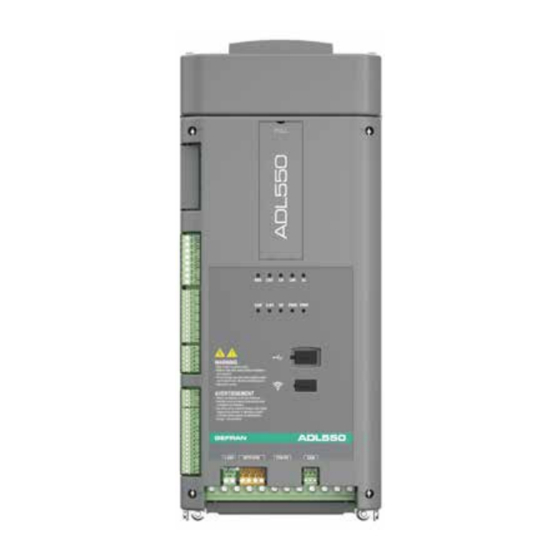
- Page 1 Vector inverter for lifts with synchronous/asynchronous motors ADL500 ..Quick start up guide Specification and installation...
-
Page 2: Information About This Manual
Gefran Drives and Motion S.r.l. has the right to modify products, data and dimensions without notice. The data can only be used for the product description and they can not be understood as legally stated properties. -
Page 3: Table Of Contents
7.3 Regulation section ................................30 7.3.1 Cable cross-sections ..................................30 7.3.2 I/O and Relays connection .................................30 7.3.3 Feedback Connection ..................................31 7.3.3.1 Phasing ............................................37 7.3.4 +24V supply connection ..................................38 7.3.5 Safety STO connection (SFTY-STO) ..............................38 ADL500 • Quick installation guide - Specifications and connection... - Page 4 7.9.5 Connection diagram for emergency maneuver (for synchronous motor only) ...................49 7.10 Braking .................................... 50 7.10.1 Braking unit (internal) ..................................50 8. Use of the optional keypad (KB-ADL500) ................51 8.1 Description ..................................51 8.1.1 Membrane keypad ....................................51 8.1.2 Meaning of LEDs ....................................51 8.2 Navigating with the optional keypad ..........................
-
Page 5: Safety Precautions
Use for intended purpose only The power drive system (electrical drive + application plant) may be used only for the application stated in the manual and only together with devices and components recommended and authorized by Gefran. Utiliser uniquement dans les conditions prévues Le système d’actionnement électrique (drive électrique + installation) ne peut être utilisé... -
Page 6: General Warnings
Risque d’incendies et d’explosions: L’utilisation des drives dans des zônes à risques (présence de vapeurs ou de poussières inflammables), peut provoquer des incendies ou des explosions. Les drives doivent être installés loin des zônes dangeureuses, et équipés de moteurs appropriés. ADL500 • Quick installation guide - Specifications and connection... -
Page 7: Instruction For Compliance With Ul Mark (Ul Requirements), U.s. And Canadian Electrical Codes
Short circuit ratings ADL500 inverters must be connected to a mains capable of supplying a symmetrical short-circuit power of less than or equal to “xxxx A rms. The values of the “xxxx” A rms short-circuit current, in accordance with UL requirements ( ASME17.5/CSA B44.1 ), for each motor power rating (Pn mot in the manual) are shown in the table below. -
Page 8: Introduction To The Product
2 - Introduction to the product The ADL500 is the result of GEFRAN’s experience in the civil lift engineering sector, gained from its commitment to working in close partnership with leading operators in the sector to develop technical solutions and application programs. -
Page 9: Dedicated Features
(optional) operating system (in preparation). GF_DriveLabs (Configurator) Enhancement of Gefran PC configurator features in the same “family feeling” programming. Includes an inte- grated real-time oscilloscope and 4 different levels of access (in preparation). USB PORT USB port for import/export of inverter files, motor pre-configuration files and selection of language. -
Page 10: Identification Of Components
Cards for controlling and regulating the closed and open-loop power section. Commands, references and reactions are connected to these. 7. Output voltage Three-phase AC voltage. 8. Speed feedback encoder (see section "7.3.3 Feedback Connection" on page 31). ADL500 • Quick installation guide - Specifications and connection... -
Page 11: Product Identification
• hardware revision The code can be read by smartphones using dedicated applications or with specific industrial readers. I.e.: S9DL5565. ADL550-2150-XBL-F-4-EMS. 41GE038956 - Fw. 100100 Appl. EFC 1.8.0. REV. HW A1 ADL500 • Quick installation guide - Specifications and connection... -
Page 12: Transport And Storage
Greatest relative air humidity occurs with the temperature @ 40°C (104°F) or if the temperature of the device is brought suddenly from -25 ...+30°C (-13°...+86°F). Greatest absolute air humidity if the device is brought suddenly from 70...15°C (158°...59°F). ADL500 • Quick installation guide - Specifications and connection... -
Page 13: Specification
Frequency range _______________________ ± 2000 Hz Max frequency ________________________ Flux vector CL control with feedback and brushless: 300Hz, FVOL: 150 Hz, VF: 600 Hz Min frequency ________________________ 0 Hz (*) referred to Full scale speed, PAR:680. ADL500 • Quick installation guide - Specifications and connection... -
Page 14: Torque Control
2150 1500 (*) ADL500 can only operate on IT networks devoid of any faults (between active parts and PE) or in the presence of temporary faults. Therefore an insulation monitor MUST be used to detect and enable prompt removal of any fault condition. -
Page 15: Output Electrical Data
The switching frequency is modified according to the inside temperature of the drive, as shown in the figure below. Figure 4.6.2: Ratio between switching frequency/heat sink temperature (kHz) T diss (°C) T diss th ADL500 • Quick installation guide - Specifications and connection... -
Page 16: Kt: Ambient Temperature Reduction Factor
4.7 Voltage level of the inverter for safe operations The minimum time between the moment in which an ADL500 inverter is disabled from the mains and that in which an operator can operate on internal parts of the inverter, without the danger of electric shock, is 5 minutes. -
Page 17: Weights And Dimensions
Figure 4.9.2:Size 2 dimensions (1:1) (1:1) Dimensions: Width x Height x Depth Weight Sizes (mm) (inches) (kg) (lbs) ADL510-2... ADL530-2... 162 x 390 x 151 6.38 x 15.35 x 5.94 15.4 ADL550-2... ADL500 • Quick installation guide - Specifications and connection... -
Page 18: Options
GRD... (E27), S00... = Jean Müller, Eltville; A70...= Ferraz. 5.2 Input chokes The three-phase mains choke is strongly recommended in order to: limit the RMS input current of the ADL500 inverter. increase the life of intermediate circuit capacitors and reliability of input diodes. reduce mains harmonic content reduce problems due to power supply via a low impedance line (≤... -
Page 19: Ac Output Chokes
5.3 AC output chokes The ADL500 inverter can be used with standard motors or motors designed specifically for use with inverters. The latter usually have a higher isolation rating to better withstand PWM voltage Examples of reference regulations are provided below: motors designed for use with inverters do not require any specific filtering of output from the inverter. -
Page 20: Emc Filter
The ADL-...-F models are standard equipped with an internal EMC filter to ensure compliance with the EN 12015 standard. Shielded motor power cables with a maximum length of 10 m must be used and the shielding must be grounded at both ends. ADL500 • Quick installation guide - Specifications and connection... -
Page 21: Ultracapacitor Energy Storage Module
Il sistema consigliato da Gefran è un convertitore DC/DC bidirezionale ad alta efficienza che integra il modulo di ac- cumulo dell'energia degli ultracondensatori e si collega all'inverter ADL500 con un semplice collegamento a due fili. -
Page 22: Mechanical Installation
25 mm ( 0.98” ) 150 mm ( 6" ) 25 mm ( 0.98 ” ) 150 mm ( 6" ) 25 mm ( 0.98” ) 25 mm ( 0.98” ) ADL500 • Quick installation guide - Specifications and connection... -
Page 23: Fastening Positions
4 x M5 x 12 mm screws + Grover (spring-lock) washer + flat washer Size 2 (ADL5...-2...) 4 x M5 x 12 mm screws + Grover (spring-lock) washer + flat washer Note! Other dimensions see chapter "4.10 Weights and dimensions" on page 17. ADL500 • Quick installation guide - Specifications and connection... -
Page 24: Wiring Procedure
7 - Wiring Procedure Adjustable frequency ADL500 drives are electrical apparatus for use in for civil lifting installations. Parts of the Drives are energized during operation. The electrical installation and the opening of the device should therefore only be carried out by qualified personnel. Improper installation of motors or Drives may therefore cause the failure Warning! of the device as well as serious injury to persons or material damage. - Page 25 CC avant d’en effectuer le branchement. Avant la mise en service des appareils, ayant été stockés pendant long temps, il faut alimenter variateurs à vide pendant deux heures, pour régénérer les condensateurs : appliquer une tension d’alimentation sans actionner le variateur. ADL500 • Quick installation guide - Specifications and connection...
-
Page 26: Location And Identification Of Terminals And Leds
Omega power shield connection "7.2.3 Connection of shielding (recommended)" on page 27 (15) Omega adjustment shield connection "7.3.3 Feedback Connection" on page 31 Operation and diagnostics LEDs "7.3.6 Led" on page 38 ADL500 • Quick installation guide - Specifications and connection... -
Page 27: Power Section
For compliance with EN 12016: put the optional metal support KIT-PWR SHIELD ASSY (A) on bolts (B) and tighten the two nuts fully (C). Fasten the power cable shield to the omega sections (D). ADL500 • Quick installation guide - Specifications and connection... -
Page 28: Emc Guide Line
Use power shield kit to connect shield of motor cable to drive. Note! For further information regarding electro-magnetic compatibility standards, according to Directive 2014/30/EU, conformity checks carried out on Gefran appliances, connection of filters and mains inductors, shielding of cables, ground connections, etc., consult the “Electro-magnetic compatibility guide”... -
Page 29: Internal Emc Filter (Standard)
7.2.7 Connection of AC and DC chokes (optional) (For three-phase ADL500 only). The drive can use both a three-phase choke on the AC power line and, for 1040 ... 2150 sizes only, a DC choke between terminals C1 and C. -
Page 30: Regulation Section
"A.1.1 - Installation" on page 87), 2) attach a spade lug connector to the signal cable shield, 3) loosen the ground screw on the metal frame, insert the fork and then screw it down. ADL500 • Quick installation guide - Specifications and connection... -
Page 31: Feedback Connection
Figure 7.3.2: Connection of shielding (recommended) Encoders provide motor speed and position feedback. The regulation algorithms in the ADL500 drive are capable of controlling asynchronous and permanent magnet synchronous (brushless) motors. With asynchronous motors the regulation algorithm may or may not use the speed measurement obtained from the encoder reading. - Page 32 Fast input 2 (**) Fast input 1 (**) 0V Fast input (**) COS- COS+ SIN- SIN+ 0VE out +VE out (*) Connection of shielding, see figure 7.3.2 (**) on ADL550 only ADL500 • Quick installation guide - Specifications and connection...
- Page 33 Max frequency __________________________ EnDat: 1 MHz with delay compensation (not programmable) SSI: 400 KHz (not programmable) Number of bits ___________________________ EnDat: max 32 bit/turn* max 32bit/turn (automatic recognition at initialisation) SSI:13-25 bits (default 25) ADL500 • Quick installation guide - Specifications and connection...
- Page 34 Interface _______________________________ EnDat: 2.1/2.2 single/multi-turn (command set managed only compatible with 2.1) Max frequency __________________________ EnDat: 1.5 MHz with delay compensation (not programmable) Number of bits ___________________________ EnDat: max 32 bit/turn* max 32bit/turn (automatic recognition at initialisation) ADL500 • Quick installation guide - Specifications and connection...
- Page 35 (7) Connection Single Ended Digital Encoder (ADL510-530-550) The following resistive divider must be added on single-ended configurations. Figure 7.3.9: resistive divider for single-ended configurations Z- or Z+ B- or B+ A- or A+ 0VEout +VEout ADL500 • Quick installation guide - Specifications and connection...
- Page 36 (8) Repeat Encoder (TTL line-driver) (ADL510-530-550) ADL500 have an incremental encoder output with TTL Line Driver levels to be used to repeat the servomotor feedback device. This function is performed via HW and an encoder output can be repeated with a programmable divider.
-
Page 37: Phasing
7.3.3.1 Phasing In order for the ADL500 Brushless regulation algorithm to function correctly, it is necessary to know the position of the rotor with respect to the stator power phases. Therefore the 0° position provided by the absolute encoder must be known with respect to the position of a motor pole and the encoder count direction must match the motor power phases. -
Page 38: Supply Connection
ADL510 ADL530 ADL550 Yellow Braking Yellow Contactor closing command status Green Enable Current limit Generic alarm Green CAN 1 S-BY Yellow Stand-by Green Direction up DOWN Green Direction down Green Power Supply ON ADL500 • Quick installation guide - Specifications and connection... -
Page 39: Eth-Pc Ethernet Interface (Rj45 Connector)
The PC is connected directly to the ADL500 drive. If the ADL500 is configured in “DHCP” (IP parameterization, PAR 9604 set to “DHCP”), since no DCHP server is avail- able in this topology, the ADL500 will acquire the local address 169.254.10.10. -
Page 40: Can Interface
If the ADL500 is configured as “static” (PAR 9604 Ip Assignment set to “Static”), the ADL500 will be reachable at the address configured in the IP Address set parameter (PAR 9556) in the network specified by the netmask in the IP Netmask set parameter (PAR 9558). -
Page 41: Optional Keypad Interface (Rj45 Connector)
7.6 Optional Keypad interface (RJ45 connector) The female RJ45 port on the front of the inverter is used to mechanically attach and connect the optional KB-ADL500 keypad. The optional KB-ADL500 keypad is automatically recognised and managed by the drive. The keypad can be used remotely from distances of up to 5 or 10 m: using the appropriate kits, codes S5P11TK1 and S5P11TK2 respectively. -
Page 42: Connection Diagrams
SAFETY EN + SAFETY EN - EN - SAFETY-STO (AD550 only) SAFETY OK1 Resettable fuse SAFETY OK2 12 +24V_OUT Isolated power supply for Inputs/Outputs 0 V (+24 V_EXT) 0V (24V)_OUT Chassis ADL500 • Quick installation guide - Specifications and connection... -
Page 43: Typical Connection Diagram
AC CHOKE KEYPAD ETH-PC OPTIONAL V1 W1 BREAKING RESISTOR USB 2.0 DC CHOKE ADL530 (ADL550: 4 to 22kW) OPTIONAL BRAKE DRIVE DOOR CONTACTOR CONTACTOR V2 W2 Emergency Failure Safety chain TRAFO BRAKE ADL500 • Quick installation guide - Specifications and connection... - Page 44 OPTIONAL AC CHOKE KEYPAD ETH-PC OPTIONAL V1 W1 BREAKING RESISTOR DC CHOKE ADL510 (ADL550: 4 to 22kW) OPTIONAL BRAKE DRIVE DOOR CONTACTOR CONTACTOR V2 W2 Emergency Failure Safety chain TRAFO BRAKE ADL500 • Quick installation guide - Specifications and connection...
-
Page 45: Emergency Connection Diagram
7.9.3 Emergency connection diagram To use this type of connection reference should be made to the safety and installation instructions in the ADL550 / ADL550-ICS "Safe Torque Off", cod. 1S95STOEN, downloadable from the Gefran website (https://www.gefran.com/en/ download/5435/attachment/en). Warning! 7.9.3.1 Emergency connection diagram with EMS module (ADL5.0-...-EMS modes) In the event of a three-phase power failure, the system manages motor movement in an emergency condition through an external battery connected to the EMS module built into the ADL510/530/550-...-EMS models. -
Page 46: Emergency Connection Diagram With Ups
S1=OFF (8) S2 can be set to ON, after a delay, manually or automatically using power failure control devices. (9) S2 must be OFF at the end of the sequence ADL500 • Quick installation guide - Specifications and connection... -
Page 47: Safety Connections
DC CHOKE ADL550 SFTY-STO (ADL550: 4 to 22kW) OPTIONAL BRAKE DRIVE DOOR CONTACTOR CONTACTOR V2 W2 Emergency Failure Safety chain TRAFO BRAKE (*): K4 and K3M must be checked by control unit ADL500 • Quick installation guide - Specifications and connection... - Page 48 (*): K4 and CONTACTORLESS OK must be checked by control unit - PAR 11088 Contactorless enable must be turn ON to configure contactorless OK output and Contactorless enable digital input (DI7). ADL500 • Quick installation guide - Specifications and connection...
-
Page 49: Connection Diagram For Emergency Maneuver (For Synchronous Motor Only)
Figure 7.9.9: Diagram of main emergency maneuver ADL550 Control Emergency Mode Card Digital input X Brake Release Sel Brake Release Sel Digital input Y Button Motor Brake Brake Contactor Contactor BR Elevator Control Panel ADL500 • Quick installation guide - Specifications and connection... -
Page 50: Braking
800 Vdc 768 Vdc 758 Vdc 670 Vdc 660 Vdc 394 Vdc 384 Vdc Note! For the combination of recommended braking resistors refer to chapter "5.4 External braking resistors" on page 19. ADL500 • Quick installation guide - Specifications and connection... -
Page 51: Use Of The Optional Keypad (Kb-Adl500)
8. Use of the optional keypad (KB-ADL500) This section describes the optional KB-ADL500 programming keypad (cod. S5P11T) and how to use it (display and programming parameters). Note ! For the connetion refer to section "7.6 Optional Keypad interface (RJ45 connector)" on page 41. -
Page 52: Navigating With The Optional Keypad
Input value too high the value entered too high Input value too low the value entered too low Out of range attempt to insert a value outside the min. and max. limits ADL500 • Quick installation guide - Specifications and connection... -
Page 53: Scanning Of The Parameters
Using the ◄ and ► keys, the cursor can be moved to all the digits, including trailing zeros that are normally not displayed. With the ▲ and ▼ keys, the digit under the cursor is increased or decreased. Press E to confirm the modification or ESC to cancel. ADL500 • Quick installation guide - Specifications and connection... - Page 54 Press E to activate modification mode. The entire line is displayed in reverse. The elements of the list of parameters associated with this parameter can be scrolled using the ▲ and ▼ keys. Press E to confirm the modification or ESC to cancel. ADL500 • Quick installation guide - Specifications and connection...
-
Page 55: How To Save Parameters
DRIVE INFO Press E to execute 04.03 DRIVE CONFIG 04.04 ALARM CONFIG 01 /18 01 /18 PAR: PAR: Save parameters Save parameters In Progress Done To exit, press the ◄ key. ADL500 • Quick installation guide - Specifications and connection... -
Page 56: Configuration Of The Display
Menu CONFIG DRIVE, parameter Display backlight, PAR: 576. Sets lighting of the display: the light of the display always stays on. (default) the light switches off approx. 3 minutes after the last key is pressed. ADL500 • Quick installation guide - Specifications and connection... -
Page 57: Alarms
(5) “Press ESC to exit” is displayed if the message requires acknowledgment. When a message is closed, the next message is displayed until the queue is empty. Note! For further information, see chapter "10.3 Messages" on page 84 ADL500 • Quick installation guide - Specifications and connection... -
Page 58: Saving And Recovery Of New Parameter Settings
Load from USB 04.02 DRIVE INFO Press E to execute 04.03 DRIVE CONFIG 04.04 ALARM CONFIG ADL _ 0000.DAT Load from USB Done ADL _ 0000.DAT ADL _ 0001.DAT ADL _ 0001.DAT ADL500 • Quick installation guide - Specifications and connection... -
Page 59: Asynchronous/Synchronous Selection
Press E to reset the drive and restart in the new operating mode. Note ! Important: the default parameters including the LIFT application are reloaded. This can only be done with the drive disabled. ADL500 • Quick installation guide - Specifications and connection... -
Page 60: Commissioning Via Keypad
(PE). Le courant de dispersion vers la terre est supérieur à 3,5 mA sur les variateurs ADL500 et sur les filtres à courant alterné. Les normes EN 61800-5-1 spécifient qu’en cas de courant de dispersion vers la terre, supérieur à 3,5 ma, la mise à la terre ( ) doit avoir une double connexion pour la redondance si sa section est inférieure à... - Page 61 Il ne faut pas éxécuter de tests de rigidité diélectrique sur des parties du convertisseurs. Pour mesurer les tensions, des signaux, il faut utiliser des instruments de mesure appropriés (résistance interne minimale 10kΩ/V). ADL500 • Quick installation guide - Specifications and connection...
-
Page 62: Drive Setup
Press E to execute Transfer the parameters from the memory connected to the drive’s USB port. Press ▼ to go to the next step or press E to load the parameters from USB. ADL500 • Quick installation guide - Specifications and connection... - Page 63 Press E to execute SG10 254 MOT3291 SG10 291 MOT3068 PAR: 392 01 STARTUP WIZARD 05 /05 Select motor 02 OPTIMIZATION WIZARD Press E to execute 03 TROUBLESHOOTING 04 DRIVE ADL500 • Quick installation guide - Specifications and connection...
-
Page 64: Startup Wizard For Asynchronous Motor
To terminate the sequence of functions and return to the menu, press the ESC key. At the end of the sequence, once the parameters have been saved, if commissioning is successful, the main menu will return. ADL500 • Quick installation guide - Specifications and connection... - Page 65 ASY SSC Value: E=Yes Down=Next 02 /09 PAR: 2000 Range: 230 ... 480V Rated voltage Def: 03 /09 PAR: 2002 Range: 1 ... 1500A Rated current 11.8 Def: 11.8 ADL500 • Quick installation guide - Specifications and connection...
- Page 66 These data are lost if the device is switched off. To save the motor data follow the procedure described in step 9. At the end of the procedure proceed to next step. ADL500 • Quick installation guide - Specifications and connection...
- Page 67 Range: 0 ... 100,000 Load wei g ht Def: 09 /09 PAR: 11156 Range: 0 ... 10000 Rope wei g ht Def: At the end of the procedure proceed to next step. ADL500 • Quick installation guide - Specifications and connection...
- Page 68 11032 Range: -10000 ... 10000 Multi speed 6 0.00 Hz Def: 0.00 Hz 08 /08 PAR: 11034 Range: -10000 ... 10000 Multi speed 7 0.00 Hz Def: 0.00 Hz ADL500 • Quick installation guide - Specifications and connection...
- Page 69 The calculated parameters are saved in a RAM memory to enable the drive to perform the necessary calculations. These data are lost if the device is switched off. To save the motor data follow the procedure described in step 7. ADL500 • Quick installation guide - Specifications and connection...
- Page 70 (1) Press the E key to start the save parameters procedure. (2) Press E to confirm (3) End of procedure (4) When the parameters have been saved correctly the drive displays this screen to show that the startup wizard is complete. ADL500 • Quick installation guide - Specifications and connection...
-
Page 71: Startup Wizard For Brushless Motors
(0) None (default), (1) Digital, (2) Sinus, 02 /07 PAR: 2132 (3) Sinus SINCOS, (4) Sinus ENDAT, Encoder mode ENDAT (5) Sinus BiSS, (6) Digital (7) BiSS, (8) Sinus SSI Value: ADL500 • Quick installation guide - Specifications and connection... - Page 72 When data entry is complete the Take parameters command is executed automatically (menu MOTOR DATA, PAR: 2020). The motor data entered during the STARTUP WIZARD procedure are saved in a RAM memory to enable the drive to perform the necessary calculations. ADL500 • Quick installation guide - Specifications and connection...
- Page 73 Range: 0 ... 100,000 Load wei g ht Def: 09 /09 PAR: 11156 Range: 0 ... 10000 Rope wei g ht Def: At the end of the procedure proceed to next step. ADL500 • Quick installation guide - Specifications and connection...
- Page 74 Multispeed 0, PAR 11020 Multispeed 1, PAR 11022 Multispeed 2, PAR 11024 Multispeed 3, PAR 11026 Multispeed 4, PAR 11028 Multispeed 5, PAR 11030 Multispeed 6, PAR 11032 Multispeed 7, PAR 11034 ADL500 • Quick installation guide - Specifications and connection...
- Page 75 The calculated parameters are saved in a RAM memory to enable the drive to perform the necessary calculations. These data are lost if the device is switched off. To save the motor data follow the procedure described in step 7. ADL500 • Quick installation guide - Specifications and connection...
- Page 76 (1) Press the E key to start the save parameters procedure. (2) Press "E" to confirm (3) End of procedure (4) When the parameters have been saved correctly the drive displays this screen to show that the startup wizard is complete. ADL500 • Quick installation guide - Specifications and connection...
-
Page 77: Troubleshooting
- If the motor is not provided with a blower: the load is too high at slow speeds. Cooling the fan on the motor shaft is not sufficient for this load cycle. - The motor is used at less than the rated frequency, causing additional magnetic losses. Solution: - Change the processing cycle. - Use a cooling fan to cool the motor. ADL500 • Quick installation guide - Specifications and connection... - Page 78 By switching the drive off and back on you can run a single travel to bring the car to a better position for the procedure. After you have changed the ropes, reset the direction change counter to eliminate the lock condition. ADL500 • Quick installation guide - Specifications and connection...
- Page 79 The application that has been downloaded uses an incorrect task number (Task). 006CH-108 The application that has been downloaded has an incorrect Crc (Tables + Code) Solution: Remove the MDPLC application or download a correct MDPLC application. ADL500 • Quick installation guide - Specifications and connection...
-
Page 80: Efc Application Alarms
Solution: Contact Gefran in order to update the firmware on the optional encoder card. Condition: an optional card has been removed with respect to the configuration present when the last Save parameters command was executed or there Opt cfg change is a fault on the optional card or on the regulation card. -
Page 81: Speed Fbk Loss Alarm According To The Type Of Feedback
Solution: Check the connection of the clock and encoder-drive data, check the connection of the screen, check the encoder supply voltage, check parameter 2102 Encoder supply, check parameter 7106 BiSS N bit ST and 7108 BiSS N bit MT. ADL500 • Quick installation guide - Specifications and connection... - Page 82 Data field operations disabled Analog monitoring inoperative Counting register overflow Encoder analog signals are unreliable Wrong synchronisation or offset 05H-07H Encoder-internal hardware fault, no operation possible 1CH-1DH Error in sampling, no operation possible ADL500 • Quick installation guide - Specifications and connection...
-
Page 83: Reset Speed Fbk Loss Alarm
Cause: Firmware on option card incompatible with firmware on regulation card. 0x200 error When this has been signalled the information obtained from the encoder is not reliable. Solution: Contact Gefran in order to update the firmware on the optional card. ADL500 • Quick installation guide - Specifications and connection... -
Page 84: Messages
- Rated speed, Motor rated speed in rpm. • (ADL500 for Asynchronous motor) Take care not to set the Rated speed parameter to the synchronous speed. The value of the Rated speed parameter must be less than: [(Rated frequency * 60) / Pole pairs]. - Page 85 Condition: this may occur when powering the drive, if the incorrect enable key is inserted for a given firmware function. xxxxH-x Solution: Ask Gefran to supply the correct key to enable the desired firmware function. ADL500 • Quick installation guide - Specifications and connection...
- Page 86 Cause: The firmware on the optional encoder card is incompatible with that on the regulation card. The information received from the encoder is not reliable Solution: Contact Gefran in order to update the firmware on the optional encoder card. Not used Fw update failed Condition: When updating the firmware, check whether the file is in the wrong format or corrupt.
-
Page 87: Appendix
Appendix A.1 - Optional cards A.1.1 - Installation Only one option card can be installed, either an EXP-IO1-ADL500 or an EXP-DCP-ADL500. Use only the screws supplied with the option card. Caution Use a Phillips screwdriver (Ph2) to loosen the 4 M3 screws (2) and then remove the top cover (1);... -
Page 88: Optional Card Exp-Io1-Adl500
Output Relay 6 (N.O. contact, 24V 1412, Dig output 2 src RO_6C Common Relay 6 Brake Contactor RO_5O Output Relay 5 (N.O. contact, 24V 1410, Dig output 1 src RO_5C Common Relay 5 Drive OK ADL500 • Quick installation guide - Specifications and connection... -
Page 89: Optional Card Exp-Dcp-Adl500
DATA + (A) REF (GROUND) For the connection reference should be made to the DCP specifications (see next screen). DATA + (A) DATA - (B) The connection have no galvanic isolation! Caution ADL500 • Quick installation guide - Specifications and connection... -
Page 90: Input/Output Features
0 (4) mA to 20 mA Input R 500 Ω Resolution 12 Bits (11 + sign) Precision 1% of full scale Isolation AI-X AI-X AI-X (*) Select input V/I (V=OFF, I=ON) ADL500 • Quick installation guide - Specifications and connection... -
Page 91: Selection Of Voltage/Current At Analog Input
ANALOG INPUTS) parameter setting and the position of P2 Jumper as shown in the figure. To access the adjustment card, remove the top cover, see section "A.1 - Optional cards" on page 87. OFF = Voltage (Default) Regulation card ON = Current ADL500 • Quick installation guide - Specifications and connection... -
Page 92: Windows Pc Network Configuration
PC’s autonomously acquire an IP address belonging to “link local” family: 169.254.x.y. If the PC’s Ethernet configuration has to be modified, for example in case of ADL500 static IP configuration, here are the operations to do: For Windows XP under Control Panel - >... -
Page 93: Brake Monitoring System
The purpose of the brake fault alarm is to check whether the states of the two feedback signals from the brake are consistent and, in case of doubt, to include a function whereby the ADL500 drive stops the system. The procedure for including the alarm is described below. -
Page 94: Maintenance Of The Brake Fault Alarm Function
The brake fault alarm function envisages signals that are normally asserted. If the wiring is functionally inverted, simply negate the corresponding digital inputs in the ADL500 configuration. To configure the brake fault alarm function, proceed as follows: 1. In the SAFETY menu , change the setting of parameter 11252 Brake Fbk A3 Sel (default Null) and select the digi- tal input corresponding to the second brake feedback signal If Brake Fbk A3 Sel is set to a value other than Null, the brake fault alarm function is automatically enabled. - Page 96 Fax +33 (0) 478770320 info@gefran.com.cn Fax +55 (0) 1132974012 commercial@gefran.fr comercial@gefran.com.br GEFRAN S.P.A. GEFRAN DRIVES AND MOTION S.R.L. Via Sebina 74 Manuale ADL500 HW+QS_EN 25050 Provaglio d’Iseo (BS) ITALY Via Carducci 24 Rev. 0.2 - 23-12-2021 Ph. +39 030 98881...
Need help?
Do you have a question about the ADL500 and is the answer not in the manual?
Questions and answers