Siemens sinumerik 840D sl Operating Manual
Turning
Hide thumbs
Also See for sinumerik 840D sl:
- Function manual (2184 pages) ,
- Programming manual (1334 pages) ,
- Commissioning manual (1102 pages)
Table of Contents
Advertisement
Quick Links
Turning
SINUMERIK
SINUMERIK 840D sl/828D
Turning
Operating Manual
Valid for:
SINUMERIK 828D with CNC system software
Version 4.3
CNC software for 840D sl/ 840DE sl
SINUMERIK Operate
for PCU/PC
07/2010
6FC5398-8CP40-0BA0
___________________
Preface
___________________
Introduction
___________________
Setting up the machine
___________________
Working in manual mode
___________________
Machining the workpiece
Simulating a machining
___________________
operation
___________________
Creating G code program
Creating a ShopTurn
___________________
program
Programming technology
___________________
functions (cycles)
___________________
Multi-channel support
___________________
User data
___________________
Teaching in a program
___________________
Working with a B axis
___________________
Tool management
___________________
Program management
___________________
Setting up drives
___________________
HT 8
___________________
Easy Message (828D only)
___________________
Easy Extend (828D only)
___________________
Service Planner (828D only)
Version 2.6 SP1
Ladder Viewer and Ladder
___________________
Version 2.6 SP1
add-on (828D only)
Alarms, error messages, and
___________________
system alarms
___________________
Appendix
1
2
3
4
5
6
7
8
9
10
11
12
13
14
15
16
17
18
19
20
21
A
Advertisement
Table of Contents

Related Manuals for Siemens sinumerik 840D sl


Summary of Contents for Siemens sinumerik 840D sl
- Page 1 Introduction ___________________ Setting up the machine ___________________ Working in manual mode SINUMERIK ___________________ Machining the workpiece Simulating a machining ___________________ SINUMERIK 840D sl/828D operation Turning ___________________ Creating G code program Creating a ShopTurn ___________________ program Operating Manual Programming technology ___________________...
- Page 2 Note the following: WARNING Siemens products may only be used for the applications described in the catalog and in the relevant technical documentation. If products and components from other manufacturers are used, these must be recommended or approved by Siemens. Proper transport, storage, installation, assembly, commissioning, operation and maintenance are required to ensure that the products operate safely and without any problems.
-
Page 3: Preface
● Researching documentation online Information on DOConCD and direct access to the publications in DOConWEB. ● Compiling individual documentation on the basis of Siemens contents with the My Documentation Manager (MDM), refer to http://www.siemens.com/mdm. My Documentation Manager provides you with a range of features for generating your own machine documentation. - Page 4 If you have any technical questions, please contact our hotline: Europe/Africa Telephone +49 911 895 7222 +49 911 895 7223 0.14 €/min from a German landline; cell phone charges may vary. Internet http://www.siemens.com/automation/support-request Americas Telephone +1 423 262 2522 +1 423 262 2200 E-mail mailto:techsupport.sea@siemens.com...
- Page 5 Preface Asia/Pacific Telephone +86 1064 757575 +86 1064 747474 E-mail mailto:support.asia.automation@siemens.com Note Country-specific telephone numbers for technical support are provided under the following Internet address: http://www.automation.siemens.com/partner Questions on If you have any queries (suggestions, corrections) in relation to this documentation, please...
- Page 6 Preface Turning Operating Manual, 07/2010, 6FC5398-8CP40-0BA0...
-
Page 7: Table Of Contents
Table of contents Preface ..............................3 Introduction.............................. 19 Product overview .........................19 Operator panel fronts ........................20 1.2.1 Overview ............................20 1.2.2 Keys of the operator panel......................22 Machine control panels ........................28 1.3.1 Overview ............................28 1.3.2 Controls on the machine control panel ..................28 User interface..........................31 1.4.1 Screen layout ..........................31 1.4.2... - Page 8 Table of contents Work offsets ..........................73 2.7.1 Display active zero offset ......................74 2.7.2 Displaying the work offset "overview" ..................75 2.7.3 Displaying and editing base zero offset ..................76 2.7.4 Displaying and editing settable zero offset ................. 77 2.7.5 Displaying the zero offset details.
- Page 9 Table of contents 4.7.2 Continuing program from search target ..................119 4.7.3 Simple search target definition....................119 4.7.4 Defining an interruption point as search target ................120 4.7.5 Entering the search target via search pointer ................121 4.7.6 Parameters for block search in the search pointer ..............122 4.7.7 Block search mode ........................123 Intervening in the program sequence ..................125...
- Page 10 Table of contents 5.10 Displaying simulation alarms..................... 168 Creating G code program ........................169 Graphical programming......................169 Program views .......................... 170 Program structure ........................173 Basic information........................174 6.4.1 Machining planes ........................174 6.4.2 Current planes in cycles and input screens ................174 6.4.3 Programming a tool (T) ......................
- Page 11 Table of contents 7.15 Calling technology functions ......................225 7.15.1 Additional functions in the input screens ...................225 7.15.2 Checking cycle parameters......................225 7.15.3 Setting data for technological functions ..................226 7.15.4 Changing a cycle call .........................226 7.16 Programming the approach/retraction cycle ................227 7.17 Measuring cycle support ......................229 7.18 Example: Standard machining ....................231...
- Page 12 Table of contents 8.4.1 Face milling (CYCLE61)......................333 8.4.2 Rectangular pocket (POCKET3)....................336 8.4.3 Circular pocket (POCKET4) ...................... 340 8.4.4 Rectangular spigot (CYCLE76)....................345 8.4.5 Circular spigot (CYCLE77)......................348 8.4.6 Multi-edge (CYCLE79) ......................351 8.4.7 Longitudinal groove (SLOT1) ....................353 8.4.8 Circumferential groove (SLOT2) ....................
- Page 13 Table of contents 8.7.17.2 Programming example: Machining, counterspindle - without previous transfer ......454 8.7.17.3 Programming example: Machining bar material ................455 8.7.17.4 Parameters, counterspindle .......................455 Multi-channel support ..........................459 Working with several channels ....................459 Multi-channel view ........................460 9.2.1 Multi-channel view in the "Machine" operating area ..............460 9.2.2 Setting the multi-channel view ....................463 Multi-channel editor........................465...
- Page 14 Table of contents 11.4.5 Teach-in A spline ........................512 11.5 Editing a block........................... 514 11.6 Selecting a block ........................515 11.7 Deleting a block......................... 516 11.8 Settings for teach-in ........................517 Working with a B axis ..........................519 12.1 Lathes with B axis ........................519 12.2 Tool alignment for turning ......................
- Page 15 Table of contents 13.14.3 Equipping multitool with tools.....................574 13.14.4 Removing a tool from multitool ....................575 13.14.5 Deleting multitool ........................576 13.14.6 Loading and unloading multitool ....................576 13.14.7 Reactivating multitool.........................577 13.14.8 Relocating a multitool.........................579 13.14.9 Positioning multitool ........................580 Program management ........................... 581 14.1 Overview ............................581 14.1.1...
- Page 16 Table of contents 16.2 Traversing keys......................... 628 16.3 Machine control panel menu ..................... 629 16.4 Virtual keyboard ........................631 16.5 Calibrating the touch panel ....................... 633 Easy Message (828D only)........................635 17.1 Overview ........................... 635 17.2 Activating Easy Message ......................637 17.3 Creating/editing a user profile ....................
- Page 17 Table of contents 20.16 Inserting/deleting a symbol table ....................674 20.17 Displaying the network symbol information table...............675 20.18 Displaying and editing PLC signals ...................676 20.19 Displaying cross references.......................677 Alarms, error messages, and system alarms ..................679 21.1 Displaying alarms........................679 21.2 Displaying an alarm log......................681 21.3 Displaying messages .........................682 21.4...
- Page 18 Table of contents Turning Operating Manual, 07/2010, 6FC5398-8CP40-0BA0...
-
Page 19: Introduction
Introduction Product overview The SINUMERIK controller is a CNC (Computerized Numerical Controller) for machine tools. You can use the CNC to implement the following basic functions in conjunction with a machine tool: ● Creation and adaptation of part programs ● Execution of part programs ●... -
Page 20: Operator Panel Fronts
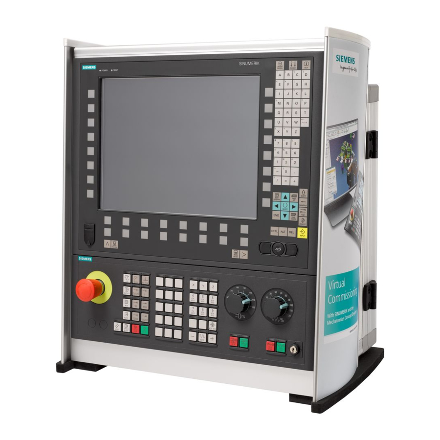
Introduction 1.2 Operator panel fronts Operator panel fronts 1.2.1 Overview Introduction The display (screen) and operation (e.g. hardkeys and softkeys) of the SINUMERIK Operate user interface use the operator panel front. In this example, the OP 010 operator panel front is used to illustrate the components that are available for operating the controller and machine tool. - Page 21 A more precise description as well as a view of the other operator panel fronts that can be used may be found in the following reference: Operator Components and Networking Manual; SINUMERIK 840D sl/840Di sl Turning Operating Manual, 07/2010, 6FC5398-8CP40-0BA0...
-
Page 22: Keys Of The Operator Panel
Introduction 1.2 Operator panel fronts 1.2.2 Keys of the operator panel The following keys and key combinations are available for operation of the control and the machine tool. Keys and key combinations Function <ALARM CANCEL> Cancels alarms and messages that are marked with this symbol. - Page 23 Introduction 1.2 Operator panel fronts Function <PAGE DOWN> + <CTRL> Positions the cursor to the lowest line of a window. <Cursor right> Editing box Opens a directory or program (e.g. cycle) in the editor. Navigation Moves the cursor further to the right by one character. <Cursor right>...
- Page 24 Introduction 1.2 Operator panel fronts Function <Cursor up> + <SHIFT> In the program manager and in the program editor, selects a contiguous selection of directories and program blocks. <Cursor down> Editing box Moves the cursor downwards. Navigation – Moves the cursor in a table to the next cell downwards. –...
- Page 25 Introduction 1.2 Operator panel fronts Function <BACKSPACE> Editing box Deletes a character selected to the left of the cursor. Navigation Deletes all of the selected characters to the left of the cursor. <BACKSPACE> + <CTRL> Deletes a word selected to the left of the cursor. <TAB>...
- Page 26 Introduction 1.2 Operator panel fronts Function <CTRL> + <V> Inserts text from the clipboard: Pastes the text from the clipboard at the actual cursor position. Pastes text from the clipboard at the position of a selected text. <CTRL> + <ALT> + <C> Creates a complete archive on an external data carrier (USB- FlashDrive).
- Page 27 Introduction 1.2 Operator panel fronts Function <INPUT> Completes input of a value in the entry field. Opens a director or a program. <ALARM> - only OP 010 and OP 010C Select the "Diagnosis" operating area. <PROGRAM> - only OP 010 and OP 010C Calls the "Program Manager"...
-
Page 28: Machine Control Panels
1.3.1 Overview The machine tool can be equipped with a machine control panel by Siemens or with a specific machine control panel from the machine manufacturer. You use the machine control panel to initiate actions on the machine tool such as traversing an axis or starting the machining of a workpiece. - Page 29 Introduction 1.3 Machine control panels Machine manufacturer For additional responses to pressing the Emergency Stop button, please refer to the machine manufacturer's instructions. Installation locations for control devices (d = 16 mm) RESET Stop processing the current programs. The NCK control remains synchronized with the machine. It is in its initial state and ready for a new program run.
- Page 30 Introduction 1.3 Machine control panels Machine manufacturer A machine data code defines how the increment value is interpreted. Customer keys T1 to T15 Traversal axes with rapid traverse superposition and coordinate exchange Axis keys Selects an axis. Direction keys Select the traversing direction. <RAPID>...
-
Page 31: User Interface
Introduction 1.4 User interface User interface 1.4.1 Screen layout Overview Active operating area and mode Alarm/message line Program name Channel state and program control Channel operational messages Axis position display in actual value window Turning Operating Manual, 07/2010, 6FC5398-8CP40-0BA0... -
Page 32: Status Display
Introduction 1.4 User interface Display for active tool T current feedrate F active spindle with current status (S) Spindle utilization rate in percent Operating window with program block display Display of active G functions, all G functions, H functions and input window for different functions (for example, skip blocks, program control) Dialog line to provide additional user notes Horizontal softkey bar... - Page 33 Introduction 1.4 User interface Display Description "Diagnosis" operating area "Start-up" operating area Active mode or submode "Jog" mode "MDA" mode "Auto" mode "Teach In" submode "Repos" submode "Ref Point" submode Alarms and messages Alarm display The alarm numbers are displayed in white lettering on a red background.
- Page 34 Introduction 1.4 User interface Machine manufacturer Please also refer to the machine manufacturer's instructions. Third line Display Description Display of channel status. If several channels are present on the machine, the channel name is also displayed. If only one channel is available, only the "Reset" channel status is displayed.
-
Page 35: Actual Value Window
Introduction 1.4 User interface 1.4.3 Actual value window The actual values of the axes and their positions are displayed. Work/Machine The displayed coordinates are based on either the machine coordinate system or the workpiece coordinate system. The machine coordinate system (Machine), in contrast to the workpiece coordinate system (Work), does not take any work offsets into consideration. -
Page 36: T,F,S Window
Introduction 1.4 User interface See also Work offsets (Page 73) 1.4.4 T,F,S window The most important data concerning the current tool, the feedrate (path feed or axis feed in JOG) and the spindle are displayed in the T, F, and S windows. Tool data Display Meaning... -
Page 37: Current Block Display
Introduction 1.4 User interface Spindle data Display Meaning Spindle selection, identification with spindle number and main spindle Speed Actual value (when spindle turns, display increases) Setpoint (always displayed, also during positioning) Symbol Spindle status Spindle not enabled Spindle is turning clockwise Spindle is turning counterclockwise Spindle is stationary Override... -
Page 38: Operation Via Softkeys And Buttons
Introduction 1.4 User interface 1.4.6 Operation via softkeys and buttons Operating areas/operating modes The user interface consists of different windows featuring eight horizontal and eight vertical softkeys. You operate the softkeys with the keys next to the softkey bars. You can display a new window or execute functions using the softkeys. The operating software is sub-divided into six operating areas (machine, parameter, program, program manager, diagnosis, startup) and five operating modes or submodes (JOG, MDA, AUTO, TEACH IN, REF POINT, REPOS). -
Page 39: Entering Or Selecting Parameters
Introduction 1.4 User interface Use the "Return" softkey to close an open window. Use the "Cancel" softkey to exit a window without accepting the entered values and return to the next highest window. When you have entered all the necessary parameters in the parameter screen form correctly, you can close the window and save the parameters using the "Accept"... - Page 40 Introduction 1.4 User interface Press the <INSERT> key. The selection options are displayed in a list. Select the required setting using the <Cursor down> and <Cursor up> keys. If required, enter a value in the associated input field. Press the <INPUT> key to complete the parameter input. Changing or calculating parameters If you only want to change individual characters in an input field rather than overwriting the entire entry, switch to insertion mode.
- Page 41 Introduction 1.4 User interface + </> Enter the division character using the <SHIFT> + </> keys. Enter bracket expressions using the <SHIFT> + <(> and <SHIFT> + <)> keys. + <)> Enter "r" or "R" as well as the number x from which you would like to <number>...
-
Page 42: Pocket Calculator
Introduction 1.4 User interface 1.4.8 Pocket calculator You can use the pocket calculator to quickly calculate parameter values during programming. If, for example, the diameter of a workpiece is only dimensioned indirectly in the workpiece drawing, i.e., the diameter must be derived from the sum of several other dimension specifications, you can calculate the diameter directly in the input field of this parameter. -
Page 43: Context Menu
Introduction 1.4 User interface Press the "Calculate" softkey. - OR - Press the <INPUT> key. The new value is calculated and displayed in the input field of the pocket calculator. Press the "Accept" softkey. The calculated value is accepted and displayed in the input field of the window. -
Page 44: Touch Operation
Introduction 1.4 User interface 1.4.10 Touch operation If you have an operator panel with a touch screen, you can perform the following functions with touch operation: Operating area switchover You can display the operating area menu by touching the display symbol for the active operating area in the status display. -
Page 45: Entering Asian Characters
Introduction 1.4 User interface Note Changing the language directly on the input screens You can switch between the user interface languages available on the controller directly on the user interface by pressing the key combination <CTRL + L>. 1.4.12 Entering Asian characters You have the possibility of entering Asian characters. - Page 46 Introduction 1.4 User interface Precondition The control has been set to Chinese or Korean. Procedure Editing characters Open the screen form and position the cursor on the entry field and press the <Alt +S> keys. The editor is displayed. Enter the desired phonetic notation. Click the <Cursor down>...
-
Page 47: Protection Levels
● Work offsets ● Setting data ● Program creation / program editing References For additional information, please refer to the following documentation: Commissioning Manual SINUMERIK Operate (IM9) / SINUMERIK 840D sl Softkeys Machine operating area Protection level End user (protection level 3) - Page 48 Introduction 1.4 User interface Diagnostics operating area Protection level Manufacturer (protection level 1) End user (protection level 3) Service (protection level 2) Startup operating area Protection levels End user (protection level 3) Keyswitch 3 (protection level 4) Keyswitch 3 (protection level 4) Key switch 3 (protection level 4) Keyswitch 3...
-
Page 49: Online Help In Sinumerik Operate
Introduction 1.4 User interface 1.4.14 Online help in SINUMERIK Operate A comprehensive context-sensitive online help is stored in the control system. ● A brief description is provided for each window and, if required, step-by-step instructions for the operating sequences. ● A detailed help is provided in the editor for every entered G code. You can also display all G functions and take over a selected command directly from the help into the editor. - Page 50 Introduction 1.4 User interface Select the desired manual with the <Cursor down> and <Cursor up> keys. Press the <Cursor right> or <INPUT> key or double-click to open the manual and the chapter. Navigate to the desired topic with the "Cursor down" key. Press the <Follow reference>...
- Page 51 Introduction 1.4 User interface Displaying and inserting a G code command in the editor A program is opened in the editor. Position the cursor on the desired G code command and press the <HELP> or the <F12> key. The associated G code description is displayed. Press the "Display all G funct."...
- Page 52 Introduction 1.4 User interface Turning Operating Manual, 07/2010, 6FC5398-8CP40-0BA0...
-
Page 53: Setting Up The Machine
Setting up the machine Switching on and switching off Start-up When the control starts up, the main screen opens according to the operating mode specified by the machine manufacturer. In general, this is the main screen for the "REF POINT" submode. Machine manufacturer Please also refer to the machine manufacturer's instructions. -
Page 54: Approaching A Reference Point
Setting up the machine 2.2 Approaching a reference point Approaching a reference point 2.2.1 Referencing axes Your machine tool can be equipped with an absolute or incremental path measuring system. An axis with incremental path measuring system must be referenced after the control has been switched-on –... - Page 55 Setting up the machine 2.2 Approaching a reference point Procedure Press the <JOG> key. Press the <REF. POINT> key. Select the axis to be traversed. Press the <-> or <+> key. The selected axis moves to the reference point. If you have pressed the wrong direction key, the action is not accepted and the axes do not move.
-
Page 56: User Agreement
Setting up the machine 2.2 Approaching a reference point 2.2.2 User agreement If you are using Safety Integrated (SI) on your machine, you will need to confirm that the current displayed position of an axis corresponds to its actual position on the machine when you reference an axis. - Page 57 Setting up the machine 2.2 Approaching a reference point The selected axis is marked with an "x" meaning "safely referenced" in the "Acknowledgement" column. By pressing the <SELECT> key again, you deactivate the acknowledgement again. Turning Operating Manual, 07/2010, 6FC5398-8P40-0BA0...
-
Page 58: Modes And Mode Groups
Setting up the machine 2.3 Modes and mode groups Modes and mode groups 2.3.1 General You can work in three different operating modes. "JOG" mode "JOG" mode is used for the following preparatory actions: ● Approach reference point, i.e. the machine axis is referenced ●... - Page 59 Setting up the machine 2.3 Modes and mode groups Selecting "Repos" Press the <REPOS> key. "MDA" mode (Manual Data Automatic) In "MDA" mode, you can enter and execute G code commands non-modally to set up the machine or to perform a single action. Selecting "MDA"...
-
Page 60: Modes Groups And Channels
Setting up the machine 2.3 Modes and mode groups 2.3.2 Modes groups and channels Every channel behaves like an independent NC. A maximum of one part program can be processed per channel. ● Control with 1channel One mode group exists. ●... -
Page 61: Channel Switchover
Another channel can be selected by pressing one of the other softkeys. References Commissioning Manual SINUMERIK Operate (IM9) / SINUMERIK 840D sl Channel switchover via touch operation On the HT 8 and when using a touch screen operating panel, you can switch to the next channel via touch operation in the status display. -
Page 62: Settings For The Machine
Setting up the machine 2.4 Settings for the machine Settings for the machine 2.4.1 Switching over the coordinate system (MCS/WCS) The coordinates in the actual value display are relative to either the machine coordinate system or the workpiece coordinate system. By default, the workpiece coordinate system is set as a reference for the actual value display. -
Page 63: Setting The Work Offset
Setting up the machine 2.4 Settings for the machine Proceed as follows Select <JOG> or <AUTO> mode in the "Machine" operating area. Press the menu forward key and the "Settings" softkey. A new vertical softkey bar appears. Press the "Switch to inch" softkey. A prompt asks you whether you really want to switch over the unit of measurement. - Page 64 Setting up the machine 2.4 Settings for the machine The actual value can be set in both the Reset and Stop state. Note Setting the WO in the Stop state If you enter the new actual value in the Stop state, the changes made are only visible and only take effect when the program is continued.
- Page 65 Setting up the machine 2.4 Settings for the machine Relative actual value Press the "REL actual values" softkey. Enter the axis positions and press the "Input" key. Note The new actual value is only displayed. The relative actual value has no effect on the axis positions and the active work offset.
-
Page 66: Measuring The Tool
Setting up the machine 2.5 Measuring the tool Measuring the tool The geometries of the machining tool must be taken into consideration when executing a part program. These are stored as tool offset data in the tool list. Each time the tool is called, the control considers the tool offset data. - Page 67 Setting up the machine 2.5 Measuring the tool Procedure Select "JOG" mode in the "Machine" operating area. Press the "Meas. tool" softkey. Press the "Manual" softkey. Press the "Select tool” softkey. The "Tool selection" window is opened. Select the tool that you wish to measure. The cutting edge position and the radius or diameter of the tool must already be entered in the tool list.
-
Page 68: Measuring A Tool With A Tool Probe
For further information about tool carriers that can be orientated, please refer to the following reference: Commissioning Manual SINUMERIK Operate / SINUMERIK 840D sl The tool offset data is then calculated from the known position of the tool carrier reference point and the probe. - Page 69 Setting up the machine 2.5 Measuring the tool Procedure Insert the tool that you want to measure. If the tool is to be measured using a tool carrier that can be orientated, then at this position the tool should be aligned in the same way that it will be subsequently measured.
-
Page 70: Calibrating The Tool Probe
Setting up the machine 2.5 Measuring the tool 2.5.3 Calibrating the tool probe To be able to measure your tools automatically, you must first determine the position of the tool probe in the machine area in relation to the machine zero. Machine manufacturer Please refer to the machine manufacturer's specifications. -
Page 71: Measuring The Workpiece Zero
Setting up the machine 2.6 Measuring the workpiece zero Measuring the workpiece zero The reference point for programming a workpiece is always the workpiece zero. To determine this zero point, measure the length of the workpiece and save the position of the cylinder's face surface in the direction Z in a work offset. - Page 72 Setting up the machine 2.6 Measuring the workpiece zero Procedure Select "JOG" mode in the "Machine" operating area. Press the "Workpiece zero" softkey. The "Set Edge" window opens. Select "Measuring only" if you only want to display the measured values. - OR - Select the desired work offset in which you want to store the zero point (e.g.
-
Page 73: Work Offsets
Setting up the machine 2.7 Work offsets Work offsets Following reference point approach, the actual value display for the axis coordinates is based on the machine zero (M) of the machine coordinate system (Machine). The program for machining the workpiece, however, is based on the workpiece zero (W) of the workpiece coordinate system (Work). -
Page 74: Display Active Zero Offset
Setting up the machine 2.7 Work offsets Coarse and fine offsets Every work offset (G54 to G57, G505 to G599) consists of a coarse offset and a fine offset. You can call the work offsets from any program (coarse and fine offsets are added together). You can save the workpiece zero, for example, in the coarse offset, and then store the offset that occurs when a new workpiece is clamped between the old and the new workpiece zero in the fine offset. -
Page 75: Displaying The Work Offset "Overview
Setting up the machine 2.7 Work offsets Procedure Select the "Parameter" operating area. Press the "Work offset" softkey. The "Work Offset - Active" window is opened. Note Further details on work offsets If you would like to see further details about the specified offsets or if you would like to change values for the rotation, scaling or mirroring, press the "Details"... -
Page 76: Displaying And Editing Base Zero Offset
Setting up the machine 2.7 Work offsets Work offsets Workpiece reference Displays the additional work offsets programmed with $P_WPFRAME. Programmed WO Displays the additional work offsets programmed with $P_PFRAME. Cycle reference Displays the additional work offsets programmed with $P_CYCFRAME. Total WO Displays the active work offset, resulting from the total of all work offsets. -
Page 77: Displaying And Editing Settable Zero Offset
Setting up the machine 2.7 Work offsets Note Activate base offsets The offsets specified here are immediately active. 2.7.4 Displaying and editing settable zero offset All settable offsets, divided into coarse and fine offsets, are displayed in the "Work Offset - G54..G599"... -
Page 78: Displaying The Zero Offset Details
Setting up the machine 2.7 Work offsets 2.7.5 Displaying the zero offset details. For each work offset, you can display and edit all data for all axes. You can also delete work offsets. For every axis, values for the following data will be displayed: ●... -
Page 79: Deleting A Work Offset
Setting up the machine 2.7 Work offsets Press the "WO +" or "WO -" softkey to select the next or previous offset, respectively, within the selected area ("Active", "Base", "G54 to G599") without first having to switch to the overview window. If you have reached the end of the range (e.g. -
Page 80: Measuring The Workpiece Zero
Setting up the machine 2.7 Work offsets 2.7.7 Measuring the workpiece zero Procedure Select the "Parameter" operating area and press the "Work offset" softkey. Press the "G54...G599" softkey and select the work offset in which the zero point is to be saved. Press the "Workpiece zero"... -
Page 81: Monitoring Axis And Spindle Data
Setting up the machine 2.8 Monitoring axis and spindle data Monitoring axis and spindle data 2.8.1 Specify working area limitations The "Working area limitation" function can be used to limit the range within which a tool can traverse in all channel axes. These commands allow you to set up protection zones in the working area which are out of bounds for tool movements. -
Page 82: Editing Spindle Data
Setting up the machine 2.8 Monitoring axis and spindle data 2.8.2 Editing spindle data The speed limits set for the spindles that must not be under- or overshot are displayed in the "Spindles" window. You can limit the spindle speeds in fields "Minimum" and "Maximum" within the limit values defined in the relevant machine data. -
Page 83: Spindle Chuck Data
Setting up the machine 2.8 Monitoring axis and spindle data 2.8.3 Spindle chuck data You store the chuck dimensions of the spindles at your machine in the "Spindle chuck data" window. Manually measuring a tool If you want to use the chuck of the main or counter spindle as a reference point during manual measuring, specify the chuck dimension ZC. - Page 84 Setting up the machine 2.8 Monitoring axis and spindle data Tailstock Dimensioning the tailstock The length of the tailstock (ZR) and the diameter of the tailstock (XR) of the spindle screen are needed for the display of the tailstock in the simulation. Procedure Select the "Parameter"...
- Page 85 Setting up the machine 2.8 Monitoring axis and spindle data Parameter Description Unit Main spindle chuck dimensions (inc) Endpiece type Dimensions of the forward edge or stop edge Jaw type 1 Jaw type 2 Chuck dimension, counter-spindle (inc) - only for a counter-spindle that has been set-up Stop dimension, counter-spindle (inc) - only for a counter-spindle that has been set-up...
-
Page 86: Displaying Setting Data Lists
Setting up the machine 2.9 Displaying setting data lists Displaying setting data lists You can display lists with configured setting data. Machine manufacturer Please refer to the machine manufacturer's specifications. Procedure Select the "Parameter" operating area. Press "Setting data" and "Data lists" softkeys. The "Setting data list"... -
Page 87: Handwheel Assignment
Setting up the machine 2.10 Handwheel assignment 2.10 Handwheel assignment You can traverse the axes in the machine coordinate system (Machine) or in the workpiece coordinate system (Work) via the handwheel. Software option You require the "Extended operator functions" option for the handwheel offset (only for 828D). - Page 88 Setting up the machine 2.10 Handwheel assignment - OR Open the "Axis" selection box using the <INSERT> key, navigate to the desired axis, and press the <INPUT> key. Selecting an axis also activates the handwheel (e.g., "X" is assigned to handwheel no. 1 and is activated immediately). Press the "Handwheel"...
-
Page 89: Mda
Setting up the machine 2.11 MDA 2.11 In "MDA" mode (Manual Data Automatic mode), you can enter G-code commands block-by- block and immediately execute them for setting up the machine. You can load an MDA program straight from the Program Manager into the MDA buffer. You may also store programs which were rendered or changed in the MDA operating window into any directory of the Program Manager. -
Page 90: Saving An Mda Program
Setting up the machine 2.11 MDA 2.11.2 Saving an MDA program Proceed as follows Select the "Machine" operating area. Press the <MDA> key. The MDA editor opens. Create the MDA program by entering the G-code commands using the operator's keyboard. Press the "Store MDA"... -
Page 91: Executing An Mda Program
Setting up the machine 2.11 MDA 2.11.3 Executing an MDA program Proceed as follows Select the "Machine" operating area. Press the <MDA> key. The MDA editor opens. Input the desired G-code commands using the operator’s keyboard. Press the <CYCLE START> key. The control executes the input blocks. - Page 92 Setting up the machine 2.11 MDA Turning Operating Manual, 07/2010, 6FC5398-8CP40-0BA0...
-
Page 93: Working In Manual Mode
Working in manual mode General Always use "JOG" mode when you want to set up the machine for the execution of a program or to carry out simple traversing movements on the machine: ● Synchronize the measuring system of the controller with the machine (reference point approach) ●... -
Page 94: Selecting A Tool And Spindle
Working in manual mode 3.2 Selecting a tool and spindle Selecting a tool and spindle 3.2.1 T,S,M window For the preparatory actions in manual mode, tool selection and spindle control are both performed centrally in a screen form. In addition to the main spindle (S1), there is another tool spindle (S2) for powered tools. Your turning machine can also be equipped with a counterspindle (S3). -
Page 95: Selecting A Tool
Working in manual mode 3.2 Selecting a tool and spindle Display Meaning G work offset Selection of the work offset (basic reference, G54 - 57) You can select work offsets from the tool list of settable work offsets via the "Work offset" softkey. Measurement unit Selection of the unit of measurement (inch, mm). -
Page 96: Starting And Stopping The Spindle Manually
Working in manual mode 3.2 Selecting a tool and spindle Press the <CYCLE START> key. The tool is automatically swung into the machining position and the name of the tool displayed in the tool status bar. 3.2.3 Starting and stopping the spindle manually Procedure Select the "T,S,M"... -
Page 97: Positioning The Spindle
Working in manual mode 3.2 Selecting a tool and spindle 3.2.4 Positioning the spindle Procedure Select the "T,S,M" softkey in the "JOG" mode. Select the "Stop Pos." setting in the "Spindle M function" field. The "Stop Pos." entry field appears. Enter the desired spindle stop position. -
Page 98: Traversing Axes
Working in manual mode 3.3 Traversing axes Traversing axes You can traverse the axes in manual mode via the Increment or Axis keys or handwheels. During a traverse initiated from the keyboard, the selected axis moves at the programmed setup feedrate. During an incremental traverse, the selected axis traverses a specified increment. -
Page 99: Traversing Axes By A Variable Increment
Working in manual mode 3.3 Traversing axes Press keys 1, 10, etc. up to 10000 in order to move the axis in a defined increment. The numbers on the keys indicate the traverse path in micrometers or micro-inches. Example: Press the "100" button for a desired increment of 100 μm (= 0.1 mm). - Page 100 Working in manual mode 3.3 Traversing axes Enter the desired value for the "Variable increment" parameter. Example: Enter 500 for a desired increment of 500 μm (0.5 mm). Press the <Inc VAR> key. Select the axis to be traversed. Press the <+> or <-> key. Each time you press the key the selected axis is traversed by the set increment.
-
Page 101: Positioning Axes
Working in manual mode 3.4 Positioning axes Positioning axes In order to implement simple machining sequences, you can traverse the axes to certain positions in manual mode. The feedrate / rapid traverse override is active during traversing. Procedure If required, select a tool. Select the "JOG"... -
Page 102: Simple Stock Removal Of Workpiece
Working in manual mode 3.5 Simple stock removal of workpiece Simple stock removal of workpiece Some blanks have a smooth or even surface. For example, you can use the stock removal cycle to turn the face surface of the workpiece before machining actually takes place. If you want to bore out a collet using the stock removal cycle, you can program an undercut (XF2) in the corner. - Page 103 Working in manual mode 3.5 Simple stock removal of workpiece Parameters Description Unit Tool name Cutting edge number Feedrate mm/rev S / V Spindle speed or constant cutting rate m/min ∇ (roughing) Machining ∇∇∇ (finishing) Position Machining position Face Machining ...
-
Page 104: Thread Synchronizing
Working in manual mode 3.6 Thread synchronizing Thread synchronizing If you wish to re-machine a thread, it may be necessary to synchronize the spindle to the existing thread turn. This is necessary as by reclamping the blank, an angular offset can occur in the thread. - Page 105 Working in manual mode 3.6 Thread synchronizing Note: The thread synchronization is activated by teaching in a spindle. In this case, the synchronizing positions of axes X and Z and the synchronizing angle of spindle (Sn) are saved in the Machine and displayed in the screen form.
-
Page 106: Default Settings For Manual Mode
Working in manual mode 3.7 Default settings for manual mode Default settings for manual mode Specify the configurations for manual mode in the "Settings for manual operation" window. Presettings Settings Description Type of feedrate Here, you select the type of feedrate. G94: Axis feedrate/linear feedrate ... -
Page 107: Machining The Workpiece
Machining the workpiece Starting and stopping machining During execution of a program, the workpiece is machined in accordance with the programming on the machine. After the program is started in automatic mode, workpiece machining is performed automatically. Requirements The following requirements must be met before executing a program: ●... - Page 108 Machining the workpiece 4.1 Starting and stopping machining Stopping machining Press the <CYCLE STOP> key. Machining stops immediately. Individual program blocks are not executed to the end. On the next start, machining is resumed from the point where it left off. Canceling machining Press the <RESET>...
-
Page 109: Selecting A Program
Machining the workpiece 4.2 Selecting a program Selecting a program Procedure Select the "Program manager" operating area. The directory overview is opened. Place the cursor on the directory containing the program that you want to select. Press the <INPUT> key - OR - Press the <Cursor right>... -
Page 110: Executing A Trail Program Run
Machining the workpiece 4.3 Executing a trail program run Executing a trail program run When testing a program, the system can interrupt the machining of the workpiece after each program block, which triggers a movement or auxiliary function on the machine. In this way, you can control the machining result block-by-block during the initial execution of a program on the machine. - Page 111 Machining the workpiece 4.3 Executing a trail program run Press the <SINGLE BLOCK> key again, if the machining is not supposed to run block-by-block. The key is deselected again. If you now press the <CYCLE START> key again, the program is executed to the end without interruption.
-
Page 112: Displaying The Current Program Block
Machining the workpiece 4.4 Displaying the current program block Displaying the current program block 4.4.1 Current block display The window of the current block display shows you the program blocks currently being executed. Display of current program The following information is displayed in the running program: ●... -
Page 113: Display Program Level
Machining the workpiece 4.4 Displaying the current program block Machine manufacturer Please refer to the machine manufacturer's specifications. Procedure A program is selected for execution and has been opened in the "Machine" operating area. Press the "Basic blocks" softkey. The "Basic Blocks" window opens. Press the <SINGLE BLOCK>... - Page 114 Machining the workpiece 4.4 Displaying the current program block Display of program level The following information will be displayed: ● Level number ● Program name ● Block number, or line number ● Remain program run throughs (only for several program run throughs) Precondition A program must be selected for execution in "AUTO"...
-
Page 115: Correcting A Program
Machining the workpiece 4.5 Correcting a program Correcting a program As soon as a syntax error in the part program is detected by the controller, program execution is interrupted and the syntax error is displayed in the alarm line. Correction possibilities Depending on the state of the control system, you can make the following corrections using the Program editing function. -
Page 116: Repositioning Axes
Machining the workpiece 4.6 Repositioning axes Repositioning axes After a program interruption in automatic mode (e.g. after a tool breaks) you can move the tool away from the contour in manual mode. The coordinates of the interrupt position will be saved. The distances traversed in manual mode are displayed in the actual value window. -
Page 117: Starting Machining At A Specific Point
Machining the workpiece 4.7 Starting machining at a specific point Starting machining at a specific point 4.7.1 Use block search If you would only like to perform a certain section of a program on the machine, then you need not start the program from the beginning. You can also start the program from a specified program block. - Page 118 Machining the workpiece 4.7 Starting machining at a specific point Cascaded search You can start another search from the "Search target found" state. The cascading can be continued any number of times after every search target found. Note Another cascaded block search can be started from the stopped program execution only if the search target has been found.
-
Page 119: Continuing Program From Search Target
Machining the workpiece 4.7 Starting machining at a specific point 4.7.2 Continuing program from search target To continue the program at the desired position, press the <CYCLE START> key twice. ● The first CYCLE START outputs the auxiliary functions collected during the search. The program is then in the Stop state. -
Page 120: Defining An Interruption Point As Search Target
Machining the workpiece 4.7 Starting machining at a specific point 4.7.4 Defining an interruption point as search target Precondition A program was selected in "AUTO" mode and interrupted during execution through CYCLE STOP or RESET. Software option You require the "Extended operator functions" option (only for 828D). Procedure Press the "Block search"... -
Page 121: Entering The Search Target Via Search Pointer
Machining the workpiece 4.7 Starting machining at a specific point 4.7.5 Entering the search target via search pointer Enter the program point which you would like to proceed to in the "Search Pointer" window. Software option You require the "Extended operator functions" option for the "Search pointer" function (only for 828D). -
Page 122: Parameters For Block Search In The Search Pointer
Machining the workpiece 4.7 Starting machining at a specific point Note Interruption point You can load the interruption point in search pointer mode. 4.7.6 Parameters for block search in the search pointer Parameter Meaning Number of program level Program: The name of the main program is automatically entered Ext: File extension Pass counter... -
Page 123: Block Search Mode
Machining the workpiece 4.7 Starting machining at a specific point 4.7.7 Block search mode Set the desired search variant in the "Search Mode" window. The set mode is retained when the the controller is shut down. When you activate the "Search"... - Page 124 Machining the workpiece 4.7 Starting machining at a specific point References For additional information, please refer to the following documentation: Commissioning Manual SINUMERIK Operate (IM9) / SINUMERIK 840D sl Procedure Select the "Machine" operating area. Press the <AUTO> key. Press the "Block search" and "Block search mode" softkeys.
-
Page 125: Intervening In The Program Sequence
Machining the workpiece 4.8 Intervening in the program sequence Intervening in the program sequence 4.8.1 Program control You can change the program sequence in the "AUTO" and "MDA" modes. Abbreviation/program Scope control The program is started and executed with auxiliary function outputs and dwell times. In this mode, the axes are not traversed. - Page 126 Machining the workpiece 4.8 Intervening in the program sequence Activating program control You can control the program sequence however you wish by selecting and clearing the relevant check boxes. Display / response of active program controls: If a program control is activated, the abbreviation of the corresponding function appears in the status display as response.
-
Page 127: Skip Blocks
Machining the workpiece 4.8 Intervening in the program sequence 4.8.2 Skip blocks It is possible to skip program blocks, which are not to be executed every time the program runs. The skip blocks are identified by placing a "/" (forward slash) or "/x (x = number of skip level) character in front of the block number. - Page 128 Machining the workpiece 4.8 Intervening in the program sequence Turning Operating Manual, 07/2010, 6FC5398-8CP40-0BA0...
-
Page 129: Overstore
Machining the workpiece 4.9 Overstore Overstore With overstore, you have the option of executing technological parameters (for example, auxiliary functions, axis feed, spindle speed, programmable instructions, etc.) before the program is actually started. The program instructions act as if they are located in a normal part program. - Page 130 Machining the workpiece 4.9 Overstore Note Block-by-block execution The <SINGLE BLOCK> key is also active in the overstore mode. If several blocks are entered in the overstore buffer, then these are executed block-by-block after each NC start Deleting blocks Press the "Delete blocks" softkey to delete program blocks you have entered.
-
Page 131: Editing A Program
Machining the workpiece 4.10 Editing a program 4.10 Editing a program With the editor, you are able to render, supplement, or change part programs. Note The maximum block length is 512 characters. Calling the editor ● The editor is started via the "Program correction" function in the "Machine" operating area. - Page 132 Machining the workpiece 4.10 Editing a program Procedure Press the "Search" softkey. A new vertical softkey bar appears. The "Search" window opens at the same time. Enter the desired search term in the "Text" field. Select "Whole words" if you want to search for whole words only. Position the cursor in the "Direction"...
-
Page 133: Exchanging Program Text
Machining the workpiece 4.10 Editing a program 4.10.2 Exchanging program text You can find and replace text in one step. Requirement The desired program is opened in the editor. Proceed as follows Press the "Search" softkey. A new vertical softkey bar appears. Press the "Find + replace"... -
Page 134: Copying/Pasting/Deleting A Program Block
Machining the workpiece 4.10 Editing a program 4.10.3 Copying/pasting/deleting a program block Precondition The program is opened in the editor. Procedure Press the "Mark" softkey. - OR - Press the <SELECT> key. Select the desired program blocks with the cursor or mouse. Press the "Copy"... -
Page 135: Renumbering A Program
Machining the workpiece 4.10 Editing a program 4.10.4 Renumbering a program You can modify the block numbering of programs opened in the editor at a later point in time. Requirement The program is opened in the editor. Procedure Press the ">>" softkey. A new vertical softkey bar appears. -
Page 136: Opening A Second Program
Machining the workpiece 4.10 Editing a program 4.10.5 Opening a second program You have the option of viewing and editing two programs simultaneously in the editor. For instance, you can copy program blocks or machining steps of a program and paste them into another program. -
Page 137: Editor Settings
Machining the workpiece 4.10 Editing a program See also Copying/pasting/deleting a program block (Page 134) 4.10.6 Editor settings Enter the default settings in the "Settings" window that are to take effect automatically when the editor is opened. Presettings Settings Meaning Number Yes: A new block number will automatically be assigned after every line automatically... - Page 138 Machining the workpiece 4.10 Editing a program Procedure Select the "Program" operating area You have activated the editor. Press the ">>" and "Settings" softkeys. The "Settings" window appears. Make the desired changes here and press the "OK" softkey to confirm your settings.
-
Page 139: Displaying G Functions And Auxiliary Functions
Machining the workpiece 4.11 Displaying G functions and auxiliary functions 4.11 Displaying G functions and auxiliary functions 4.11.1 Selected G functions 16 selected G groups are displayed in the "G Function" window. Within a G group, the G function currently active in the controller is displayed. Some G codes (e.g. - Page 140 Machining the workpiece 4.11 Displaying G functions and auxiliary functions G groups displayed by default (ISO code) Group Meaning G group 1 Modally active motion commands (e.g. G0, G1, G2, G3) G group 2 Non-modally active motion commands, dwell time (e.g. G4, G74, G75) G group 3 Programmable offsets, working area limitations and pole programming (e.g.
-
Page 141: All G Functions
References For more information about configuring the displayed G groups, refer to the following document: Commissioning Manual SINUMERIK Operate (IM9) / SINUMERIK 840D sl 4.11.2 All G functions All G groups and their group numbers are listed in the "G Functions" window. -
Page 142: Auxiliary Functions
Machining the workpiece 4.11 Displaying G functions and auxiliary functions Procedure Select the "Machine" operating area. Press the <JOG>, <MDA> or <AUTO> key. Press the ">>" and "All G functions" softkeys. The "G Functions" window is opened. 4.11.3 Auxiliary functions Auxiliary functions include M and H functions preprogrammed by the machine manufacturer, which transfer parameters to the PLC to trigger reactions defined by the manufacturer. - Page 143 Machining the workpiece 4.11 Displaying G functions and auxiliary functions Press the "H functions" softkey. The "Auxiliary Functions" window opens. Press the "H functions" softkey again to hide the window again. You can display status information for diagnosing synchronized actions in the "Synchronized Actions"...
- Page 144 Machining the workpiece 4.11 Displaying G functions and auxiliary functions Procedure Select the "Machine" operating area. Press the <AUTO>, <MDA> or <JOG> key. Press the menu forward key and the "Synchron." softkey. The "Synchronized Actions" window appears. You obtain a display of all activated synchronized actions. Press the "ID"...
-
Page 145: Displaying The Program Runtime And Counting Workpieces
Machining the workpiece 4.12 Displaying the program runtime and counting workpieces 4.12 Displaying the program runtime and counting workpieces To gain an overview of the program runtime and the number of machined workpieces, open the "Times, Counter" window. Machine manufacturer Please refer to the machine manufacturer's specifications. - Page 146 Machining the workpiece 4.12 Displaying the program runtime and counting workpieces Procedure Select the "Machine" operating area. Press the <AUTO> key. Press the "Times, Counter" softkey. The "Times, Counter" window opens. Select "Yes" under "Count workpieces" if you want to count completed workpieces.
-
Page 147: Setting For Automatic Mode
Machining the workpiece 4.13 Setting for automatic mode 4.13 Setting for automatic mode Before machining a workpiece, you can test the program in order to identify programming errors early on. Use the dry run feedrate for this purpose. In addition, you have the option of additionally limiting the traversing speed for rapid traverse so that when running-in a new program with rapid traverse, no undesirable high traversing speeds occur. - Page 148 Machining the workpiece 4.13 Setting for automatic mode Enter the desired percentage in the "Reduced rapid traverse RG0" field. RG0 has not effect if you do not change the specified amount of 100%. Enter "Automatic" in the "Display measurement result" box if the measurement result window should be automatically opened, or "Manual", if the measurement result window should be opened by pressing the "Measurement result"...
-
Page 149: Simulating A Machining Operation
Simulating a machining operation Overview During simulation, the current program is calculated in its entirety and the result displayed in graphic form. The result of programming is verified without traversing the machine axes. Incorrectly programmed machining steps are detected at an early stage and incorrect machining on the workpiece prevented. - Page 150 The tailstock is only visible with the option "ShopMill/ShopTurn". Machine manufacturer Please also refer to the machine manufacturer's specifications. References Commissioning Manual SINUMERIK Operate (IM9) / SINUMERIK 840D sl Simulation display You can choose one of the following types of display: ● Material removal simulation During simulation or simultaneous recording you can follow stock removal from the defined blank.
- Page 151 Simulating a machining operation 5.1 Overview Views The following views are available for all three variants: ● Side view ● Half section ● Front view ● 3D view ● 2-window Status display The current axis coordinates, the override, the current tool with cutting edge, the current program block, the feedrate and the machining time are displayed.
- Page 152 Simulating a machining operation 5.1 Overview Supplementary conditions ● All of the existing data records (toolcarrier / TRAORI, TRANSMIT, TRACYL) are evaluated and must be correctly commissioned for correct simulation. ● Transformations with swiveled linear axis (TRAORI 64 - 69) as well as OEM transformations (TRAORI 4096 - 4098) are not supported.
-
Page 153: Simulation Before Machining Of The Workpiece
Simulating a machining operation 5.2 Simulation before machining of the workpiece Simulation before machining of the workpiece Before machining the workpiece on the machine, you have the option of performing a quick run-through in order to graphically display how the program will be executed. This provides a simple way of checking the result of the programming. - Page 154 Simulating a machining operation 5.2 Simulation before machining of the workpiece Press the "Reset" softkey to cancel the simulation. Press the "Start" softkey to restart or continue the simulation. Note Operating area switchover The simulation is exited if you switch into another operating area. If you restart the simulation, then this starts again at the beginning of the program.
-
Page 155: Simultaneous Recording Before Machining Of The Workpiece
Simulating a machining operation 5.3 Simultaneous recording before machining of the workpiece Simultaneous recording before machining of the workpiece Before machining the workpiece on the machine, you can graphically display the execution of the program on the screen to monitor the result of the programming. You can replace the programmed feedrate with a dry run feedrate to influence the speed of execution and select the program test to disable axis motion. -
Page 156: Simultaneous Recording During Machining Of The Workpiece
Simulating a machining operation 5.4 Simultaneous recording during machining of the workpiece Simultaneous recording during machining of the workpiece If the view of the work space is blocked by coolant, for example, while the workpiece is being machined, you can also track the program execution on the screen. Software option You require the option "Simultaneous recording (real-time simulation)"... -
Page 157: Different Views Of A Workpiece
Simulating a machining operation 5.5 Different views of a workpiece Different views of a workpiece In the graphical display, you can choose between different views so that you constantly have the best view of the current workpiece machining, or in order to display details or the overall view of the finished workpiece. -
Page 158: Face View
Simulating a machining operation 5.5 Different views of a workpiece 5.5.3 Face view Start the simulation. Press the "Other views" and "Face view" softkeys. The side view shows the workpiece in the X-Y plane. Changing the display You can increase or decrease the size of the simulation graphic and move it, as well as change the segment. -
Page 159: 2-Window
Simulating a machining operation 5.5 Different views of a workpiece 5.5.5 2-window Start the simulation. Press the "Additional views" and "2-window view" softkeys. The 2-window view contains a side view (left-hand window) and a front view (right-hand window) of the workpiece. The viewing direction is always from the front to the cutting surface even if machining is to be performed from behind or from the back side. -
Page 160: Graphical Display
Simulating a machining operation 5.6 Graphical display Graphical display Figure 5-1 2-window view Active window The currently active window has a lighter background than the other view windows. Switch over the active window using the <Next Window> key. You can change the workpiece display here, e.g. increase or decrease the size, turn it and move it. -
Page 161: Editing The Simulation Display
Simulating a machining operation 5.7 Editing the simulation display Editing the simulation display 5.7.1 Entering blank details You have the option of replacing the blank defined in the program or to define a blank for programs in which a blank definition cannot be inserted. Note The unmachined part can only be entered if simulation or simultaneous recording is in the reset state. -
Page 162: Program Control During The Simulation
Simulating a machining operation 5.8 Program control during the simulation Program control during the simulation 5.8.1 Changing the feedrate You can change the feedrate at any time during the simulation. You can track the changes in the status line. Note If you are working with the "Simultaneous recording"... -
Page 163: Simulating The Program Block By Block
Simulating a machining operation 5.8 Program control during the simulation 5.8.2 Simulating the program block by block You can control the program execution during simulation, i.e. execute a program block by block, as when executing a program. Procedure Simulation is started. Press the "Program control"... -
Page 164: Editing And Adapting A Simulation Graphic
Simulating a machining operation 5.9 Editing and adapting a simulation graphic Editing and adapting a simulation graphic 5.9.1 Enlarging or reducing the graphical representation Precondition The simulation or the simultaneous recording is started. Procedure Press the <+> and <-> keys if you wish to enlarge or reduce the graphic display. -
Page 165: Panning A Graphical Representation
Simulating a machining operation 5.9 Editing and adapting a simulation graphic 5.9.2 Panning a graphical representation Precondition The simulation or the simultaneous recording is started. Procedure Press a cursor key if you wish to move the graphic up, down, left, or right. -
Page 166: Modifying The Viewport
Simulating a machining operation 5.9 Editing and adapting a simulation graphic Press the "Arrow right", "Arrow left", "Arrow up", "Arrow down", "Arrow clockwise" and "Arrow counterclockwise" softkeys to change the position of the workpiece. - OR - Keep the <Shift> key pressed and then turn the workpiece in the desired direction using the appropriate cursor keys. -
Page 167: Defining Cutting Planes
Simulating a machining operation 5.9 Editing and adapting a simulation graphic Press the "Magnify -" or <-> softkey to reduce the frame. - OR - Press one of the cursor keys to move the frame up, down, left or right. Press the "Accept"... -
Page 168: Displaying Simulation Alarms
Simulating a machining operation 5.10 Displaying simulation alarms 5.10 Displaying simulation alarms Alarms might occur during simulation. If an alarm occurs during a simulation run, a window opens in the operating window to display it. The alarm overview contains the following information: ●... -
Page 169: Creating G Code Program
Creating G code program Graphical programming Functions The following functionality is available: ● Technology-oriented program step selection (cycles) using softkeys ● Input windows for parameter assignment with animated help screens ● Context-sensitive online help for every input window ● Support with contour input (geometry processor) Call and return conditions ●... -
Page 170: Program Views
Creating G code program 6.2 Program views Program views You can display a G code program in various ways. ● Program view ● Parameter screen, either with help screen or graphic view Program view The program view in the editor provides an overview of the individual machining steps of a program. - Page 171 Creating G code program 6.2 Program views Press the <Cursor right> or <Input> key to open a selected program block or cycle in the program view. The associated parameter screen with help screen is then displayed. Parameter screen with help display Using the <Cursor right>...
- Page 172 Creating G code program 6.2 Program views The color symbols Red arrow = tool traverses in rapid traverse Green arrow = tool moves with the machining feedrate Parameter screen with graphic view Using the "Graphic view" softkey, you can toggle between the help screen and the graphic view in the screen.
-
Page 173: Program Structure
Creating G code program 6.3 Program structure Program structure G_code programs can always be freely programmed. The most important commands that are included in the rule: ● Set a machining plane ● Call a tool (T and D) ● Call a work offset ●... -
Page 174: Basic Information
Creating G code program 6.4 Basic information Basic information 6.4.1 Machining planes A plane is defined by means of two coordinate axes. The third coordinate axis (tool axis) is perpendicular to this plane and determines the infeed direction of the tool (e.g. for 2½-D machining). -
Page 175: Programming A Tool (T)
Creating G code program 6.4 Basic information ● Turning: G18 (ZX) The plane is transferred to the cycles as new parameter. The plane is output in the cycle, i.e. the cycle runs in the entered plane. It is also possible to leave the plane fields empty and thus create a plane-independent program. -
Page 176: Generating A G Code Program
Creating G code program 6.5 Generating a G code program Generating a G code program Create a separate program for each new workpiece that you would like to produce. The program contains the individual machining steps that must be performed to produce the workpiece. -
Page 177: Blank Input
Creating G code program 6.6 Blank input Blank input 6.6.1 Function Function The blank is used for the simulation and the simultaneous recording. A useful simulation can only be achieved with a blank that is as close as possible to the real blank. Create a separate program for each new workpiece that you would like to produce. - Page 178 Creating G code program 6.6 Blank input Procedure Select the "Program" operating area. Press the "Misc." and "Blank" softkeys. The "Blank Input" window opens. Parameter Description Unit Data for Selection of the spindle for the blank Main spindle Counterspindle ...
-
Page 179: Machining Plane, Milling Direction, Retraction Plane, Safe Clearance And Feedrate (Pl, Rp, Sc, F)
Creating G code program 6.7 Machining plane, milling direction, retraction plane, safe clearance and feedrate (PL, RP, SC, F) Machining plane, milling direction, retraction plane, safe clearance and feedrate (PL, RP, SC, F) In the program header, cycle input screens have general parameters that always repeat. You will find the following parameters in every input screen for a cycle in a G code program. -
Page 180: Selection Of The Cycles Via Softkey
Creating G code program 6.8 Selection of the cycles via softkey Selection of the cycles via softkey Overview of the machining steps The following machining steps are available. All of the cycles/functions available in the control are shown in this display. However, at a specific system, only the steps possible corresponding to the selected technology can be selected. - Page 181 Creating G code program 6.8 Selection of the cycles via softkey ⇒ ⇒ ⇒ ⇒ ⇒ Turning Operating Manual, 07/2010, 6FC5398-8CP40-0BA0...
- Page 182 Creating G code program 6.8 Selection of the cycles via softkey ⇒ ⇒ ⇒ ⇒ ⇒ ⇒ ⇒ Turning Operating Manual, 07/2010, 6FC5398-8CP40-0BA0...
- Page 183 Creating G code program 6.8 Selection of the cycles via softkey ⇒ ⇒ ⇒ ⇒ ⇒ ⇒ ⇒ Turning Operating Manual, 07/2010, 6FC5398-8CP40-0BA0...
- Page 184 Creating G code program 6.8 Selection of the cycles via softkey ⇒ ⇒ ⇒ ⇒ ⇒ ⇒ ⇒ Turning Operating Manual, 07/2010, 6FC5398-8CP40-0BA0...
- Page 185 Creating G code program 6.8 Selection of the cycles via softkey ⇒ ⇒ See also General (Page 251) Generating a G code program (Page 176) Turning Operating Manual, 07/2010, 6FC5398-8CP40-0BA0...
-
Page 186: Calling Technology Cycles
These are then generated with the appropriate default values when the cycles are called. For additional information, please refer to the following references: Commissioning Manual SINUMERIK Operate (IM9) / SINUMERIK 840D sl Cycle support Example Use the softkeys to select whether you want support for programming contours, turning, drilling or milling cycles. -
Page 187: Checking Cycle Parameters
Creating G code program 6.9 Calling technology cycles 6.9.3 Checking cycle parameters The entered parameters are already checked during the program creation in order to avoid faulty entries. If a parameter is assigned an illegal value, this is indicated in the input screen and is designated as follows: ●... -
Page 188: Additional Functions In The Input Screens
Creating G code program 6.9 Calling technology cycles 6.9.5 Additional functions in the input screens Selection of units If, for example, the unit can be switched in a field, this is highlighted as soon as the cursor is positioned on the element. In this way, the operator recognizes the dependency. -
Page 189: Measuring Cycle Support
The tool geometry measured is entered in the appropriate tool offset data set. References You will find a more detailed description on how to use measuring cycles in: HMI sl / SINUMERIK 840D sl Programming Manual Measuring Cycles Turning Operating Manual, 07/2010, 6FC5398-8CP40-0BA0... - Page 190 Creating G code program 6.10 Measuring cycle support Procedure Press the menu forward key. Press the horizontal "Measure turning" softkey. Using a vertical softkey, select the desired measurement function group, e.g. "Calibrate probe". - OR - Measure workpiece - OR - Calibrate workpiece probe - OR - Measure tool...
-
Page 191: Creating A Shopturn Program
Creating a ShopTurn program Graphic program control, ShopTurn programs The program editor offers graphic programming to generate machining step programs that you can directly generate at the machine. Software option You require the "ShopMill/ShopTurn" option to generate ShopTurn machining step programs. Functions The following functionality is available: ●... -
Page 192: Program Views
Creating a ShopTurn program 7.2 Program views Program views You can display a ShopTurn program in various views: ● Process plan ● Programming graphics ● Parameter screen, either with help display or programming graphics Process plan The process plan in the editor provides an overview of the individual machining steps of a program. - Page 193 Creating a ShopTurn program 7.2 Program views Programming graphics The programming graphics show the contour of the workpiece as a dynamic graphic with dotted lines. The program block selected in the process plan is highlighted in color in the programming graphics. Figure 7-2 Programming graphics of a ShopTurn program Parameter screen with help display and programming graphics...
- Page 194 Creating a ShopTurn program 7.2 Program views Figure 7-3 Parameter screen with dynamic help display The animated help displays are always displayed with the correct orientation to the selected coordinate system. The parameters are dynamically displayed in the graphic. The selected parameter is displayed highlighted in the graphic.
-
Page 195: Program Structure
Creating a ShopTurn program 7.3 Program structure Program structure A machining step program is divided into three sub-areas: ● Program header ● Program blocks ● End of program These sub-areas form a process plan. Program header The program header contains parameters that affect the entire program, such as blank dimensions or retraction planes. -
Page 196: Basic Information
Creating a ShopTurn program 7.4 Basic information Basic information 7.4.1 Machining planes A workpiece can be machined on different planes. Two coordinate axes define a machining plane. On lathes with X, Z, and C axes, three planes are available: ● Turning ●... - Page 197 Creating a ShopTurn program 7.4 Basic information Face/Face C The Face/Face C machining plane corresponds to the X/Y plane (G17). For machines without a Y axis, however, the tools can only move in the X/Z plane. The X/Y coordinates that have been entered are automatically transformed into a movement in the X and C axis. You can use face surface machining with a C axis for drilling and milling if, for instance, you want to mill a pocket on the face surface.
-
Page 198: Machining Cycle, Approach/Retraction
Creating a ShopTurn program 7.4 Basic information 7.4.2 Machining cycle, approach/retraction Approaching and retracting during the machining cycle always follows the same pattern if you have not defined a special approach/retraction cycle. If your machine has a tailstock, you can also take this into consideration when traversing. The retraction for a cycle ends at the safety clearance. - Page 199 Creating a ShopTurn program 7.4 Basic information Taking into account the tailstock Figure 7-6 Approach/retraction taking into account the tailstock ● The tool traverses in rapid traverse from the tool change point along the shortest path to the retraction plane XRR from the tailstock. ●...
-
Page 200: Absolute And Incremental Dimensions
Creating a ShopTurn program 7.4 Basic information 7.4.3 Absolute and incremental dimensions When generating a machining step program, you can input positions in absolute or incremental dimensions, depending on how the workpiece drawing is dimensioned. You can also use a combination of absolute and incremental dimensions, i.e. one coordinate as an absolute dimension and the other as an incremental dimension. - Page 201 Creating a ShopTurn program 7.4 Basic information Incremental dimensions (INC) With incremental dimensions (also referred to as sequential dimensions) a position specification refers to the previously programmed point, i.e. the input value corresponds to the path to be traversed. As a rule, the plus/minus sign does not matter when entering the incremental value, only the absolute value of the increment is evaluated.
-
Page 202: Polar Coordinates
Creating a ShopTurn program 7.4 Basic information 7.4.4 Polar coordinates You can specify positions using right-angled coordinates or polar coordinates. If a point in a workpiece drawing is defined by a value for each coordinate axis, you can easily input the position into the parameter screen form using right-angled coordinates. For workpieces that are dimensioned with arcs or angular data, it is often easier if you input the positions using polar coordinates. -
Page 203: Entering The Master Dimension
Creating a ShopTurn program 7.4 Basic information 7.4.5 Entering the master dimension If you would like to finish your workpiece to an exact fit, you can input the master dimension directly into the parameter screen form during programming. Specify the master dimension as follows: F<Diameter/Length>... -
Page 204: Creating A Shopturn Program
Creating a ShopTurn program 7.5 Creating a ShopTurn program Creating a ShopTurn program Create a separate program for each new workpiece that you would like to produce. The program contains the individual machining steps that must be performed to produce the workpiece. - Page 205 Creating a ShopTurn program 7.5 Creating a ShopTurn program The retraction for a cycle ends at the safety clearance. Only the subsequent cycle moves to the retraction plane. This enables a special approach/retraction cycle to be used. Changes to the retraction plane therefore take effect when retracting from the previous machining operation.
-
Page 206: Program Header
Creating a ShopTurn program 7.6 Program header Program header In the program header, set the following parameters, which are effective for the complete program. Parameters Description Unit Measurement unit The setting of the measurement unit in the program header only refers to the position data in the actual program. - Page 207 Creating a ShopTurn program 7.6 Program header Parameters Description Unit Retraction plane X external ∅ (abs) or retraction plane X referred to XA (inc) Retraction plane X internal ∅ (abs) or retraction plane X referred to XI (inc) Retraction plane Z front (abs) or retraction plane Z referred to ZA (inc) Retraction plant Z rear Tailstock...
-
Page 208: Generating Program Blocks
Creating a ShopTurn program 7.7 Generating program blocks Generating program blocks After a new program is created and the program header is filled out, define the individual machining steps in program blocks that are necessary to machine the workpiece. You can only create the program blocks between the program header and the program end. Procedure Selecting a technological function Position the cursor in the process plan on the line behind which a new... -
Page 209: Tool, Offset Value, Feedrate And Spindle Speed (T, D, F, S, V)
Creating a ShopTurn program 7.8 Tool, offset value, feedrate and spindle speed (T, D, F, S, V) Tool, offset value, feedrate and spindle speed (T, D, F, S, V) The following parameters should be entered for every program block. Tool (T) Each time a workpiece is machined, you must program a tool. - Page 210 Creating a ShopTurn program 7.8 Tool, offset value, feedrate and spindle speed (T, D, F, S, V) Feedrate (F) The feedrate F (also referred to as the machining feedrate) specifies the speed at which the axes move when machining the workpiece. The machining feedrate is entered in mm/min, mm/rev or in mm/tooth.
- Page 211 Creating a ShopTurn program 7.8 Tool, offset value, feedrate and spindle speed (T, D, F, S, V) Machining When machining some cycles, you can choose between roughing, finishing, or complete machining. For certain milling cycles, finishing edge or finishing base are possible. ●...
-
Page 212: Call Work Offsets
Creating a ShopTurn program 7.9 Call work offsets Call work offsets You can call work offsets (G54, etc.) from any program. You define work offsets in work offset lists. You can also view the coordinates of the selected offset here. Procedure Press the "Various", "Transformations"... -
Page 213: Repeating Program Blocks
Creating a ShopTurn program 7.10 Repeating program blocks 7.10 Repeating program blocks If certain steps when machining a workpiece have to be executed more than once, it is only necessary to program these steps once. You have the option of repeating program blocks. Start and end marker You must mark the program blocks that you want to repeat with a start and end marker. - Page 214 Creating a ShopTurn program 7.10 Repeating program blocks Enter the names of the start and end markers and the number of times the blocks are to be repeated. Press the "Accept" softkey. The marked program blocks are repeated. Turning Operating Manual, 07/2010, 6FC5398-8CP40-0BA0...
-
Page 215: Entering The Number Of Workpieces
Creating a ShopTurn program 7.11 Entering the number of workpieces 7.11 Entering the number of workpieces If you wish to produce a certain quantity of the same workpiece, then at the end of the program, specify that you wish to repeat the program. If your machine has a bar loader for example, you can program the reloading of the workpiece and then the actual machining at the beginning of the program. -
Page 216: Changing Program Blocks
Creating a ShopTurn program 7.12 Changing program blocks 7.12 Changing program blocks You can subsequently optimize the parameters in the programmed blocks or adapt them to new situations, e.g. if you want to increase the feedrate or shift a position. In this case, you can directly change all the parameters in every program block in the associated parameter screen form. -
Page 217: Changing Program Settings
Creating a ShopTurn program 7.13 Changing program settings 7.13 Changing program settings Function All parameters specified in the program header with the exception of the blank shape and the unit of measurement can be changed at any point in the program. It is also possible to change the basic setting for the direction of rotation of machining in the case of milling. - Page 218 Creating a ShopTurn program 7.13 Changing program settings Parameters Parameter Description Unit Retraction Lift mode simple Extended Retraction plane X external ∅ (abs) or retraction plane X referred to XA (inc) Retraction plane X internal ∅ (abs) or retraction plane X referred to XI (inc) - (only for retraction "extended"...
-
Page 219: Selection Of The Cycles Via Softkey
Creating a ShopTurn program 7.14 Selection of the cycles via softkey 7.14 Selection of the cycles via softkey Overview of the machining steps The following machining steps are available. All of the cycles/functions available in the control are shown in this display. However, at a specific system, only the steps possible corresponding to the selected technology can be selected. - Page 220 Creating a ShopTurn program 7.14 Selection of the cycles via softkey ⇒ ⇒ ⇒ ⇒ Turning Operating Manual, 07/2010, 6FC5398-8CP40-0BA0...
- Page 221 Creating a ShopTurn program 7.14 Selection of the cycles via softkey ⇒ ⇒ ⇒ ⇒ ⇒ ⇒ Turning Operating Manual, 07/2010, 6FC5398-8CP40-0BA0...
- Page 222 Creating a ShopTurn program 7.14 Selection of the cycles via softkey ⇒ ⇒ ⇒ ⇒ ⇒ ⇒ Turning Operating Manual, 07/2010, 6FC5398-8CP40-0BA0...
- Page 223 Creating a ShopTurn program 7.14 Selection of the cycles via softkey ⇒ ⇒ ⇒ ⇒ ⇒ ⇒ ⇒ ⇒ ⇒ ⇒ ⇒ ⇒ Turning Operating Manual, 07/2010, 6FC5398-8CP40-0BA0...
- Page 224 Creating a ShopTurn program 7.14 Selection of the cycles via softkey ⇒ ⇒ ⇒ ⇒ ⇒ ⇒ Turning Operating Manual, 07/2010, 6FC5398-8CP40-0BA0...
-
Page 225: Calling Technology Functions
Creating a ShopTurn program 7.15 Calling technology functions 7.15 Calling technology functions 7.15.1 Additional functions in the input screens Selection of units If, for example, the unit can be switched in a field, this is highlighted as soon as the cursor is positioned on the element. -
Page 226: Setting Data For Technological Functions
Setting data for technological functions Technological functions can be influenced and corrected using machine or setting data. For additional information, please refer to the following documentation: Commissioning Manual SINUMERIK Operate / SINUMERIK 840D sl 7.15.4 Changing a cycle call You have called the desired cycle via softkey in the program editor, entered the parameters and confirmed with "Accept". -
Page 227: Programming The Approach/Retraction Cycle
Creating a ShopTurn program 7.16 Programming the approach/retraction cycle 7.16 Programming the approach/retraction cycle If you wish to shorten the approach/retraction for a machining cycle or solve a complex geometrical situation when approaching/retracting, you can generate a special cycle. In this case, the approach/retraction strategy normally used is not taken into account. - Page 228 Creating a ShopTurn program 7.16 Programming the approach/retraction cycle Parameters Description Unit Feedrate to approach the first position mm/min Alternatively, rapid traverse 1. position ∅ (abs) or 1st position (inc) mm (in) 1. position (abs or inc) Feedrate for approach to the second position mm/min Alternatively, rapid traverse 2.
-
Page 229: Measuring Cycle Support
The tool geometry measured is entered in the appropriate tool offset data set. References You will find a more detailed description on how to use measuring cycles in: HMI sl / SINUMERIK 840D sl Programming Manual Measuring Cycles Turning Operating Manual, 07/2010, 6FC5398-8CP40-0BA0... - Page 230 Creating a ShopTurn program 7.17 Measuring cycle support Procedure Press the menu forward key. Press the horizontal "Measure turning" softkey. Using a vertical softkey, select the desired measurement function group, e.g. "Calibrate probe". - OR - Measure workpiece - OR - Calibrate workpiece probe - OR - Measure tool...
-
Page 231: Example: Standard Machining
Creating a ShopTurn program 7.18 Example: Standard machining 7.18 Example: Standard machining General information The following example is described in detail as ShopTurn program. A G code program is generated in the same way; however, some differences must be observed. If you copy the G code program listed below, read it into the control and open it in the editor, then you can track the individual program steps. -
Page 232: Workpiece Drawing
Creating a ShopTurn program 7.18 Example: Standard machining 7.18.1 Workpiece drawing 7.18.2 Programming 1. Program header Specify the blank. Measurement unit mm Blank Cylinder 90 abs +1.0 abs -120 abs -100 abs Retraction simple Turning Operating Manual, 07/2010, 6FC5398-8CP40-0BA0... - Page 233 Creating a ShopTurn program 7.18 Example: Standard machining 2 inc 5 inc Tool change point Machine 160 abs 409 abs 4000 rev/min Machining direction Climbing Press the "Accept" softkey. The work plan is displayed. Program header and end of program are created as program blocks.
- Page 234 Creating a ShopTurn program 7.18 Example: Standard machining 3. Input of blank contour with contour computer Press the "Cont. turn." and "New contour" softkeys. The "New Contour" input window opens. Enter the contour name (in this case: Cont_1). The contour calculated as NC code is written as internal subprogram between a start and an end marker containing the entered name.
- Page 235 Creating a ShopTurn program 7.18 Example: Standard machining Press the "Accept" softkey. It is only necessary to enter the blank contour when using a pre- machined blank. Blank contour 4. Input of finished part with contour computer Press the "Cont. turn." and "New contour" softkeys. The "New Contour"...
- Page 236 Creating a ShopTurn program 7.18 Example: Standard machining Enter the following contour elements and acknowledge using the "Accept" softkey. 48 abs α2 90° Direction of rotation 23 abs 60 abs -35 abs Afterwards, entry fields are inactive. Using the "Dialog selection" softkey, select a required contour element and confirm using the "Dialog accept"...
- Page 237 Creating a ShopTurn program 7.18 Example: Standard machining Press the "Accept" softkey. Finished-part contour 5. Stock removal (roughing) Press the "Cont. turn." and "Stock removal" softkeys. The "Stock Removal" input window opens. Enter the following technology parameters: T Roughing tool 80 D1 F 0.350 mm/rev V 400 m/min Enter the following parameters:...
- Page 238 Creating a ShopTurn program 7.18 Example: Standard machining Cutting depth 0.4 inc 0.2 inc Cylinder 0 inc 0 inc Relief cuts Set machining area limits Press the "Accept" softkey. If a blank programmed under "CONT_1" is used, under parameter "BL", the "Contour" blank description should be selected instead of "Cylinder".
- Page 239 Creating a ShopTurn program 7.18 Example: Standard machining 6. Solid machine residual material Press the "Cont. turn." and "St. remov. resid." softkeys. The "Stock removal residual material" input window opens. Enter the following technology parameters: T Roughing tool_55 D1 F 0.35 mm/rev V 400 m/min Enter the following parameters: Machining...
- Page 240 Creating a ShopTurn program 7.18 Example: Standard machining 7. Stock removal (finishing) Press the "Cont. turn." and "Stock removal" softkeys. The "Stock Removal" input window opens. Enter the following technology parameters: T Finishing tool_D1 F 0.1 mm/rev V 450 m/min Enter the following parameters: Machining Finishing (∇∇∇)
- Page 241 Creating a ShopTurn program 7.18 Example: Standard machining α1 15 Degrees α2 15 Degrees 2 inc 0.4 inc 0.2 inc Press the "Accept" softkey. Contour, groove Turning Operating Manual, 07/2010, 6FC5398-8CP40-0BA0...
- Page 242 Creating a ShopTurn program 7.18 Example: Standard machining 9. Groove (finishing) Press the "Turning", "Groove" and "Groove with inclines" softkeys. The "Groove 2" entry field opens. Enter the following technology parameters: T Grooving tool F 0.1 mm/rev V 220 m/min Enter the following parameters: Machining Finishing (∇∇∇)
- Page 243 Creating a ShopTurn program 7.18 Example: Standard machining 2 mm/rev 995 rev/min Machining type Roughing (∇) Infeed: Constant cutting Diminishing cross-section Thread External thread 48 abs 0 abs -25 abs 4 inc 4 inc 1.227 inc αP 30 Degrees Infeed 0.150 inc 1 inc Multiple threads...
- Page 244 Creating a ShopTurn program 7.18 Example: Standard machining 0 abs -25 abs 4 inc 4 inc 1.227 inc αP 30 Degrees Infeed 1 inc Multiple threads α0 0 Degrees Press the "Accept" softkey. 12. Drilling Press the "Drilling", "Drilling reaming" and "Drilling" softkeys. The "Drilling"...
- Page 245 Creating a ShopTurn program 7.18 Example: Standard machining 13. Positioning Press the "Drilling", "Positions" and "Freely Programmable Positions" softkeys. The "Positions" input window opens. Enter the following parameters: Machined surface Face C Coordinate system Polar 0 abs 0 abs 16 abs 90 abs 16 abs 180 abs...
-
Page 246: Results/Simulation Test
Creating a ShopTurn program 7.18 Example: Standard machining α0 4 Degrees 5 inc 50 % 0.1 mm Insertion Vertical 0.015 mm/tooth Press the "Accept" softkey. 7.18.3 Results/simulation test Figure 7-10 Programming graphics Turning Operating Manual, 07/2010, 6FC5398-8CP40-0BA0... - Page 247 Creating a ShopTurn program 7.18 Example: Standard machining Figure 7-11 Process plan Program test by means of simulation During simulation, the current program is calculated in its entirety and the result displayed in graphic form. Figure 7-12 3D view Turning Operating Manual, 07/2010, 6FC5398-8CP40-0BA0...
-
Page 248: G Code Machining Program
Creating a ShopTurn program 7.18 Example: Standard machining 7.18.4 G code machining program N1 G54 N2 WORKPIECE(,,"","CYLINDER",192,2,-120,-100,90) N3 G0 X200 Z200 Y0 ;***************************************** N4 T="ROUGHING TOOL_80" D1 N5 M06 N6 G96 S350 M04 N7 CYCLE951(90,2,-1.6,0,-1.6,0,1,2,0,0.1,12,0,0,0,1,0.3,0,2,1110000) N8 G96 S400 N9 CYCLE62(,2,"E_LAB_A_CONT_2","E_LAB_E_CONT_2") N10 CYCLE952("STOCK REMOVAL_1",,"BLANK_1",2301311,0.35,0.15,0,4,0.1,0.1,0.4,0.2,0.1,0,1,0,0,,,,,2,2,,,0,1,,0,12,1110110) N11 G0 X200 Z200... - Page 249 Creating a ShopTurn program 7.18 Example: Standard machining ;***************************************** N34 T="DRILL_D5" D1 N35 M06 N36 SPOS=0 N37 SETMS(2) N38 M24 ; couple-in driven tool, machine-specific N39 G97 S3183 M3 N40 G94 F318 N41 TRANSMIT N42 MCALL CYCLE82(1,0,1,,10,0,0,1,11) N43 HOLES2(0,0,16,0,30,4,1010,0,,,1) N44 MCALL N45 M25 ;...
- Page 250 Creating a ShopTurn program 7.18 Example: Standard machining X30 ;*GP* ;CON,2,0.0000,1,1,MST:0,0,AX:Z,X,K,I;*GP*;*RO*;*HD* ;S,EX:0,EY:30;*GP*;*RO*;*HD* ;LL,EX:-40;*GP*;*RO*;*HD* ;LA,EX:-45,EY:40;*GP*;*RO*;*HD* ;LL,EX:-65;*GP*;*RO*;*HD* ;LA,EX:-70,EY:45;*GP*;*RO*;*HD* ;LL,EX:-95;*GP*;*RO*;*HD* ;LD,EY:0;*GP*;*RO*;*HD* ;LR,EX:0;*GP*;*RO*;*HD* ;LA,EX:0,EY:30;*GP*;*RO*;*HD* ;#End contour definition end - Don't change!;*GP*;*RO*;*HD* E_LAB_E_CONT_1: N65 E_LAB_A_CONT_2: ;#SM Z:4 ;#7__DlgK contour definition begin - Don't change!;*GP*;*RO*;*HD* G18 G90 DIAMOF;*GP* G0 Z0 X0 ;*GP* G1 X24 CHR=3 ;*GP* Z-18.477 ;*GP*...
-
Page 251: Programming Technology Functions (Cycles)
Programming technology functions (cycles) Drilling 8.1.1 General General geometry parameters ● Retraction plane RP and reference point Z0 Normally, reference point Z0 and retraction plane RP have different values. The cycle assumes that the retraction plane is in front of the reference point. Note If the values for reference point and retraction planes are identical, a relative depth specification is not permitted. -
Page 252: Centering (Cycle81)
Programming technology functions (cycles) 8.1 Drilling The hole centers should therefore be programmed before or after the cycle call as follows (see also Section, Cycles on single position or position pattern (MCALL)): ● A single position should be programmed before the cycle call ●... - Page 253 Programming technology functions (cycles) 8.1 Drilling Parameters, G code program parameters, ShopTurn program Machining plane Tool name Retraction plane Cutting edge number Safety clearance Feedrate mm/min mm/rev S / V Spindle speed or constant cutting rate m/min Parameters Description Unit Single position Machining ...
-
Page 254: Drilling (Cycle82)
Programming technology functions (cycles) 8.1 Drilling 8.1.3 Drilling (CYCLE82) Function With the "Drilling" function, the tool drills with the programmed spindle speed and feedrate down to the specified final drilling depth (shank or tip). The tool is retracted after a programmed dwell time has elapsed. Approach/retraction 1. -
Page 255: Reaming (Cycle85)
Programming technology functions (cycles) 8.1 Drilling Parameters Description Unit Face C Machining surface Face Y (only for Peripheral surface C ShopTurn) Peripheral surface Y Please note that when machining in the face C and peripheral surface C planes, clamping only remains active for the drilling operation. - Page 256 Programming technology functions (cycles) 8.1 Drilling Procedure The part program or ShopTurn program to be processed has been created and you are in the editor. Press the "Drilling" softkey. Press the "Drilling Reaming" softkey. Press the "Reaming" softkey. The "Reaming" input window opens. Parameters, G code program Parameters, ShopTurn program Machining plane...
-
Page 257: Deep-Hole Drilling (Cycle83)
Programming technology functions (cycles) 8.1 Drilling 8.1.5 Deep-hole drilling (CYCLE83) Function With the "Deep-hole drilling" cycle, the tool is inserted in the workpiece with the programmed spindle speed and feedrate in several infeed steps until the depth Z1 is reached. The following can be specified: ●... - Page 258 Programming technology functions (cycles) 8.1 Drilling Procedure The part program or ShopTurn program to be processed has been created and you are in the editor. Press the "Drilling" softkey. Press the "Deep-hole drilling" softkey. The "Deep-hole Drilling" input window opens. Parameters, G code program Parameters, ShopTurn program Machining plane...
- Page 259 Programming technology functions (cycles) 8.1 Drilling Parameters Description Unit Drilling depth (abs) or drilling depth in relation to Z0 (inc) It is inserted into the workpiece until it reaches Z1. - (for tip centering only) (only for G code) Z1 (face) or Drilling depth (abs) or drilling depth in relation to Z0 of X0 (inc) X1 (peripheral The tool is inserted until Z1 or X1 is reached.
-
Page 260: Boring (Cycle86)
Programming technology functions (cycles) 8.1 Drilling 8.1.6 Boring (CYCLE86) Function With the "Boring" cycle, the tool approaches the programmed position in rapid traverse, allowing for the retraction plane and safety clearance. It is then inserted into the workpiece at the feedrate programmed under F until it reaches the programmed depth (Z1). There is an oriented spindle stop with the SPOS command. -
Page 261: Tapping (Cycle84, 840)
Programming technology functions (cycles) 8.1 Drilling Parameter Description Unit Machining plane Retraction plane (abs) Safety clearance (inc) Single position Machining position Drill hole at programmed position. Position pattern Position with MCALL Direction of rotation Reference point Z Drilling depth (abs) or drilling depth in relation to Z0 (inc) Dwell time at final drilling depth in seconds ... - Page 262 Programming technology functions (cycles) 8.1 Drilling ● With compensating chuck: CYCLE840 ● Without compensating chuck: CYCLE84 When tapping with compensating chuck, the thread is produced in one cut. CYCLE84 enables tapping to be performed in several cuts, when the spindle is equipped with a measuring system.
- Page 263 Programming technology functions (cycles) 8.1 Drilling Approach/retraction during chipbreaking 1. The tool drills at the programmed spindle speed S (dependent on %S) as far as the first infeed depth (maximum infeed depth D). 2. Spindle stop and dwell time DT. 3.
- Page 264 Programming technology functions (cycles) 8.1 Drilling Parameters Description Unit Z0 (only for G Reference point Z code) Machining - (with You can select the following technologies for tapping: compensating with encoder chuck) Tapping with spindle encoder without encoder (only for G code) Tapping without spindle encoder;...
- Page 265 Programming technology functions (cycles) 8.1 Drilling Parameters Description Unit Pitch ... in MODULUS: MODULUS = Pitch/π - (selection MODULUS only possible for in turns per inch: Used with pipe threads, for example. Turns/" table selection When entered per inch, enter the integer number in front of the decimal point in the "without") first parameter field and the figures after the decimal point as a fraction in the second and third field.
-
Page 266: Drill And Thread Milling (Cycle78)
Programming technology functions (cycles) 8.1 Drilling Parameters Description Unit Technology – Exact stop – Precontrol – Acceleration – Spindle Behavior the same as it was before the cycle was called Exact stop (only for technology, G601: Block advance for exact stop fine ... - Page 267 Programming technology functions (cycles) 8.1 Drilling 1. The tool bores at drilling feedrate F1 to the first drilling depth D. If the final drilling depth Z1 is not reached, the tool will travel back to the workpiece surface in rapid traverse for stock removal.
- Page 268 Programming technology functions (cycles) 8.1 Drilling Parameters Description Unit Maximum depth infeed Percentage for each additional infeed DF=100: Infeed increment remains constant DF<100: Infeed increment is reduced in direction of final drilling depth Z1. Example: last infeed 4 mm; DF 80% next infeed = 4 x 80% = 3.2 mm next but one infeed = 3.2 x 80% = 2.56 mm etc.
-
Page 269: Positioning And Position Patterns
Programming technology functions (cycles) 8.1 Drilling Parameters Description Unit Selection - (not Selection, table value: e.g. for table M3; M10; etc. (ISO metric) "Without") W3/4"; etc. (Whitworth BSW) G3/4"; etc. (Whitworth BSP) N1" - 8 UNC; etc. (UNC) ... -
Page 270: Approach/Retraction
Programming technology functions (cycles) 8.1 Drilling Programming a position pattern in ShopTurn Several position patterns can be programmed in succession (up to 20 technologies and position patterns in total). They are executed in the order in which you program them. The programmed technologies and subsequently programmed positions are automatically linked by the control. -
Page 271: Arbitrary Positions (Cycle802)
Programming technology functions (cycles) 8.1 Drilling 8.1.10 Arbitrary positions (CYCLE802) Function The "Arbitrary positions" cycle allows you to program positions freely, i.e. rectangular or polar. Individual positions are approached in the order in which you program them. Press softkey "Delete all" to delete all positions programmed in X/Y. Procedure The part program or ShopTurn program to be processed has been created and you are in the editor. - Page 272 Programming technology functions (cycles) 8.1 Drilling Parameters Description Unit Face C and face Y - at right angles: Z coordinate of the reference point (abs) Positioning angle for machining area (only for face Y) Degrees X coordinate of 1st position (abs) Y coordinate of 1st position (abs) ...
-
Page 273: Position Pattern Line (Holes1), Grid Or Frame (Cycle801)
Programming technology functions (cycles) 8.1 Drilling Parameters Description Unit Peripheral surface C - cylindrical: C coordinate of 1st position (abs) Degrees 1. Position of hole with reference to Z axis (abs) ...C7 C coordinate for additional positions (abs or inc) Degrees Incremental dimension: The sign is also evaluated. - Page 274 Programming technology functions (cycles) 8.1 Drilling Procedure The part program or ShopTurn program to be processed has been created and you are in the editor. Press the "Drilling" softkey. Press the "Positions" and "Line" softkeys. The "Position Pattern" input window opens. Parameters Description Unit...
- Page 275 Programming technology functions (cycles) 8.1 Drilling Parameters Description Unit Face Y: Z coordinate of the reference point (abs) Positioning angle for machining area Degrees X coordinate of the reference point – first position (abs) Y coordinate of the reference point – first position (abs) α0 Angle of rotation of line in relation to the X axis Degrees...
-
Page 276: Circle Position Pattern (Holes2)
Programming technology functions (cycles) 8.1 Drilling 8.1.12 Circle position pattern (HOLES2) Function You can program holes on a full circle or pitch circle with defined radius with the "Circle position pattern" cycle. The basic angle of rotation (α0) for the 1st position is relative to the X axis. - Page 277 Programming technology functions (cycles) 8.1 Drilling Parameters Description Unit Face C: center/ Position circle center on the face surface off-center Position circle off-center on the face surface Z coordinate of the reference point (abs) X coordinate of the reference point (abs) – (only for off-center) Y coordinate of the reference point (abs) –...
- Page 278 Programming technology functions (cycles) 8.1 Drilling Parameters Description Unit Peripheral surface C: Cylinder diameter ∅ (abs) Z coordinate of the reference point (abs) α0 Starting angle for first position referred to the Y axis. Degrees Positive angle: Circle is rotated counterclockwise. Negative angle: Circle is rotated clockwise.
-
Page 279: Repeating Positions
Programming technology functions (cycles) 8.1 Drilling 8.1.13 Repeating positions Function If you want to approach positions that you have already programmed again, you can do this quickly with the function "Repeat position". You must specify the number of the position pattern. This cycle automatically assigns this number. -
Page 280: Rotate
Programming technology functions (cycles) 8.2 Rotate Rotate 8.2.1 General In all turning cycles apart from contour turning (CYCLE95), in the combined roughing and finishing mode, when finishing it is possible to reduce the feedrate as a percentage. Machine manufacturer Please also refer to the machine manufacturer's specifications. 8.2.2 Stock removal (CYCLE951) Function... - Page 281 Programming technology functions (cycles) 8.2 Rotate Machine manufacturer Please also refer to the machine manufacturer's instructions. If the tool does not round the corner at the end of the cut, it is raised by the safety distance or a value specified in the machine data at rapid traverse. The cycle always observes the lower value;...
- Page 282 Programming technology functions (cycles) 8.2 Rotate Straight stock removal cycle with radii or chamfers. The "Stock removal 2" input window opens. - OR Stock removal cycle with oblique lines, radii, or chamfers. The "Stock Removal 3" input window opens. Parameters, G code program Parameters, ShopTurn program Machining plane Tool name...
-
Page 283: Groove (Cycle930)
Programming technology functions (cycles) 8.2 Rotate Parameter Description Unit FS1...FS3 or R1...R3 Chamfer width (FS1...FS3) or rounding radius (R1...R3) - (not for stock removal 1) Parameter selection of intermediate point The intermediate point can be determined through position specification or angle. The following combinations are possible - (not for stock removal 1 and 2) XM ZM ... - Page 284 Programming technology functions (cycles) 8.2 Rotate Approach/retraction during roughing Infeed depth D > 0 1. The tool first moves to the starting point calculated internally in the cycle at rapid traverse. 2. The tool cuts a groove in the center of infeed depth D. 3.
- Page 285 Programming technology functions (cycles) 8.2 Rotate - OR Groove cycle on an incline with inclines, radii or chamfers. The "Groove 3" input window opens. Parameters, G code program Parameters, ShopTurn program Machining plane Tool name Safety clearance Cutting edge number Feedrate mm/min Feedrate...
-
Page 286: Undercut Form E And F (Cycle940)
Programming technology functions (cycles) 8.2 Rotate Parameters Description Unit FS1...FS4 or R1...R4 Chamfer width (FS1...FS4) or rounding radius (R1...R4) - (only for grooves 2 and α0 Angle of the incline – (only for groove 3) Degrees 8.2.4 Undercut form E and F (CYCLE940) Function You can use the "Undercut form E"... - Page 287 Programming technology functions (cycles) 8.2 Rotate Parameters, G code program (undercut, form E) Parameters, ShopTurn program (undercut, form E) Machining plane Tool name Safety clearance Cutting edge number Feedrate mm/min Feedrate mm/min mm/rev S / V Spindle speed or constant cutting rate m/min Parameters...
-
Page 288: Thread Undercuts (Cycle940)
Programming technology functions (cycles) 8.2 Rotate Parameters Description Unit Position Form F machining position: Undercut size according to DIN table: e.g.: F0.6 x 0.3 (undercut form F) Reference point X ∅ Reference point Z Allowance in X ∅ (abs) or allowance in X (inc) Allowance in Z (abs) or allowance in Z (inc) –... - Page 289 Programming technology functions (cycles) 8.2 Rotate Procedure The part program or ShopTurn program to be processed has been created and you are in the editor. Press the "Turning" softkey. Press the "Undercut" softkey. Press the "Thread undercut DIN" softkey. The "Thread Undercut (DIN 76)" input window opens. - OR - Press the "Thread undercut"...
- Page 290 Programming technology functions (cycles) 8.2 Rotate Parameters Description Unit Reference point Z α Insertion angle Degrees Cross feed ∅ (abs) or cross feed (inc) - (only for ∇∇∇ and ∇ + ∇∇∇) Maximum depth infeed – (only for ∇ and ∇ + ∇∇∇) U or UX Finishing allowance in X or finishing allowance in X and Z –...
-
Page 291: Thread Turning (Cycle99)
Programming technology functions (cycles) 8.2 Rotate Parameters Description Unit U or UX Finishing allowance in X or finishing allowance in X and Z – (only for ∇ and ∇ + ∇∇∇) Finishing allowance in Z – (only for UZ, ∇ and ∇ + ∇∇∇) 8.2.6 Thread turning (CYCLE99) Function... - Page 292 Programming technology functions (cycles) 8.2 Rotate 4. Thread with advance: The tool moves at rapid traverse to the return distance VR and then to the next starting position. Thread with run-in: The tool moves at rapid traverse to the return distance VR and then back to the starting position.
- Page 293 Programming technology functions (cycles) 8.2 Rotate Parameters Description Unit Table Thread table selection: without ISO metric Whitworth BSW Whitworth BSP Selection - (not for Data, table value, e.g. M10, M12, M14, ... table "Without") Select the thread pitch / turns for table "without" or specify the thread pitch/turns mm/rev corresponding to the selection in the thread table: in/rev...
- Page 294 Programming technology functions (cycles) 8.2 Rotate Parameters Description Unit Thread advance (inc) The starting point for the thread is the reference point (X0, Z0) brought forward by the thread advance W. The thread advance can be used if you wish to begin the individual cuts slightly earlier in order to also produce a precise start of thread.
- Page 295 Programming technology functions (cycles) 8.2 Rotate Parameters Description Unit Thread changeover depth (inc) First machine all thread turns sequentially to thread changeover depth DA, then machine all thread turns sequentially to depth 2 · DA, etc. until the final depth is reached. DA = 0: Thread changeover depth is not taken into account, i.e.
- Page 296 Programming technology functions (cycles) 8.2 Rotate Parameters Description Unit Linear: Infeed (only for ∇ and ∇ + ∇∇∇) Infeed with constant cutting depth Degressive: Infeed with constant cutting cross-section Thread Internal thread External thread Reference point X ∅ (abs, always diameter) Reference point Z (abs) X1 or End point X ∅...
- Page 297 Programming technology functions (cycles) 8.2 Rotate Parameters Description Unit D1 or ND First infeed depth or number of roughing cuts (only for ∇ and The respective value is displayed when you switch between the number of ∇ + ∇∇∇) roughing cuts and the first infeed. Finishing allowance in X and Z –...
- Page 298 Programming technology functions (cycles) 8.2 Rotate Parameters Description Unit Thread pitch in mm/revolution mm/rev in/rev Thread pitch in inch/revolution turns/" Thread turns per inch MODULUS Thread pitch in MODULUS Change in thread pitch per revolution - (only for P = mm/rev or in/rev) G = 0: The thread pitch P does not change.
- Page 299 Programming technology functions (cycles) 8.2 Rotate Parameters Description Unit Thread run-out (inc) The thread run-out can be used if you wish to retract the tool obliquely at the end of the thread (e.g. lubrication groove on a shaft). Thread depth (inc) Infeed slope as flank (inc) –...
-
Page 300: Thread Chain (Cycle98)
Programming technology functions (cycles) 8.2 Rotate 8.2.7 Thread chain (CYCLE98) Function With this cycle, you can produce several concatenated cylindrical or tapered threads with a constant pitch in longitudinal and face machining, all of which can have different thread pitches. There may be single or multiple threads. - Page 301 Programming technology functions (cycles) 8.2 Rotate Parameters, G code program Parameters, ShopTurn program Machining plane Tool name Safety clearance Cutting edge number Feedrate mm/min Feedrate mm/min mm/rev S / V Spindle speed or constant cutting rate m/min Parameters Description Unit ∇...
-
Page 302: Cut-Off (Cycle92)
Programming technology functions (cycles) 8.2 Rotate Parameters Description Unit End point X ∅ (abs) or End point 3 in relation to X2 (inc) or Thread taper 3 End point Z ∅ (abs) or End point with reference to Z2 (inc) ... - Page 303 Programming technology functions (cycles) 8.2 Rotate Approach/retraction 1. The tool first moves to the starting point calculated internally in the cycle at rapid traverse. 2. The chamfer or radius is machined at the machining feedrate. 3. Cut-off down to depth X1 is performed at the machining feedrate. 4.
- Page 304 Programming technology functions (cycles) 8.2 Rotate Parameters Description Unit Direction of spindle rotation Maximum speed limit - (only for constant cutting rate V) rev/min Reference point in X ∅ (abs, always diameter) Reference point in Z (abs) FS or R Chamfer width or rounding radius Depth for speed reduction ∅...
-
Page 305: Contour Turning
Programming technology functions (cycles) 8.3 Contour turning Contour turning 8.3.1 General information Function You can machine simple or complex contours with the "Contour turning" cycle. A contour comprises separate contour elements, whereby at least two and up to 250 elements result in a defined contour. -
Page 306: Representation Of The Contour
Programming technology functions (cycles) 8.3 Contour turning 5. Remove residual material (roughing) When removing stock along the contour, ShopTurn automatically detects residual material that has been left. For G code programming, when removing stock, it must first be decided whether to machine with residual material detection - or not. A suitable tool will allow you to remove this without having to machine the contour again. -
Page 307: Creating A New Contour
Programming technology functions (cycles) 8.3 Contour turning Foreground Background Meaning Black Blue Cursor on active element Black Orange Cursor on current element Black White Normal element White Element not currently evaluated (element will only be evaluated when it is selected with the cursor) Graphic display The progress of contour programming is shown in broken-line graphics while the contour... - Page 308 Programming technology functions (cycles) 8.3 Contour turning Press the "Contour" and "New contour" softkeys. The "New Contour" input window opens. Enter a name for the new contour. The contour name must be unique. Press the "Accept" softkey. The input window for the starting point of the contour appears. Enter the individual contour elements (see Section "Creating contour elements").
-
Page 309: Creating Contour Elements
Programming technology functions (cycles) 8.3 Contour turning 8.3.4 Creating contour elements Creating contour elements After you have created a new contour and specified the starting point, you can define the individual elements that make up the contour. The following contour elements are available for the definition of a contour: ●... - Page 310 Programming technology functions (cycles) 8.3 Contour turning Additional functions The following additional functions are available for programming a contour: ● Tangent to preceding element You can program the transition to the preceding element as tangent. ● Selecting a dialog box If two different possible contours result from the parameters entered thus far, one of the options must be selected.
- Page 311 Programming technology functions (cycles) 8.3 Contour turning The input screen to enter the contour opens, in which you initially enter a starting point for the contour. This is marked in the lefthand navigation bar using the "+" symbol. Press the "Accept" softkey. Enter the individual contour elements of the machining direction.
- Page 312 Programming technology functions (cycles) 8.3 Contour turning Contour element "Straight line e.g. Z" Parameters Description Unit End point Z (abs or inc) α1 Starting angle to Z axis Degrees α2 Angle to the preceding element Degrees Transition to next Type of transition element Radius ...
- Page 313 Programming technology functions (cycles) 8.3 Contour turning Parameters Description Unit Thread Length Z1 Length Z2 Radius R1 Radius R2 Insertion depth Chamfer Transition to following element - chamfer Grinding allowance Grinding allowance to right of contour Grinding allowance to left of contour ...
-
Page 314: Changing The Contour
Programming technology functions (cycles) 8.3 Contour turning Parameters Description Unit β1 End angle to Z axis Degrees β2 Opening angle Degrees Transition to next Type of transition element Radius Chamfer Radius Transition to following element - radius Chamfer Transition to following element - chamfer Grinding allowance Grinding allowance to right of contour... -
Page 315: Contour Call (Cycle62) - Only For G Code Program
Programming technology functions (cycles) 8.3 Contour turning Enter the parameters in the input screen or delete the element and select a new element. Press the "Accept" softkey. The desired contour element is inserted in the contour or changed. Procedure for deleting a contour element Open the part program or ShopTurn program to be executed. -
Page 316: Stock Removal (Cycle952)
Programming technology functions (cycles) 8.3 Contour turning Procedure The part program to be executed has been created and you are in the editor. Press the "Contour turning" softkey. Press the "Contour" and "Contour call" softkeys. The "Contour Call" input window opens. Assign parameters to the contour selection. - Page 317 Programming technology functions (cycles) 8.3 Contour turning When set to "automatic", rounding is always performed if the angle between the cutting edge and the contour exceeds a certain value. The angle is set in a machine data element. Machine manufacturer Please refer to the machine manufacturer's specifications.
- Page 318 Programming technology functions (cycles) 8.3 Contour turning Name convention For multi-channel systems, cycles attach a "_C" and a two-digit number of the specific channel to the names of the programs to be generated, e.g. for channel 1 "_C01". This is the reason that the name of the main program must not end with "_C" and a two-digit number.
- Page 319 Programming technology functions (cycles) 8.3 Contour turning Parameters, G code program Parameters, ShopTurn program Name of the program to be generated Tool name Machining plane Cutting edge number Retraction plane Feedrate mm/min mm/rev Safety clearance S / V Spindle speed or constant cutting rate m/min Feedrate...
- Page 320 Programming technology functions (cycles) 8.3 Contour turning Parameters Description Unit Always round on the contour. Never round on the contour. Only round to the previous intersection. Uniform cut segmentation Round cut segmentation at the edge Constant cutting depth Alternating cutting depth - (only with align cut segmentation to edge) Maximum depth infeed - (only for position parallel to the contour and UX) UX or U Finishing allowance in X or finishing allowance in X and Z –...
-
Page 321: Stock Removal Rest (Cycle952)
Programming technology functions (cycles) 8.3 Contour turning Parameters Description Unit Set machining area Set machining area limits limits – XA: 1. Limit XA ∅ – 2nd limit XB ∅ (abs) or 2nd limit referred to XA (inc) – ZA: 1. Limit ZA –... - Page 322 Programming technology functions (cycles) 8.3 Contour turning Parameters, G code program Parameters, ShopTurn program Name of the program to be generated Tool name Machining plane Cutting edge number Retraction plane Feedrate mm/min mm/rev Safety clearance S / V Spindle speed or constant cutting rate m/min Feedrate...
-
Page 323: Plunge-Cutting (Cycle952)
Programming technology functions (cycles) 8.3 Contour turning Parameters Description Unit Allowance Allowance for pre-finishing - (only for ∇∇∇) U1 contour allowance Compensation allowance in X and Z direction (inc) – (only for allowance) Positive value: Compensation allowance is kept ... - Page 324 Programming technology functions (cycles) 8.3 Contour turning Feedrate interruption To prevent the occurrence of excessively long chips during machining, you can program a feedrate interruption. Machining type You can freely select the machining type (roughing or finishing). For more detailed information, please refer to section "Stock removal". Procedure The part program or ShopTurn program to be processed has been created and you are in the editor.
- Page 325 Programming technology functions (cycles) 8.3 Contour turning Parameters Description Unit front Position back internal external Maximum depth infeed - (only for ∇) 1. Grooving limit tool (abs) – (only for face machining direction) 2. Grooving limit tool (abs) – (only for face machining direction) UX or U Finishing allowance in X or finishing allowance in X and Z –...
-
Page 326: Plunge-Cutting Rest (Cycle952)
Programming technology functions (cycles) 8.3 Contour turning 8.3.10 Plunge-cutting rest (CYCLE952) Function The "Grooving residual material" function is used when you want to machine the material that remained after grooving along the contour. During grooving, the cycle automatically detects any residual material and generates an updated blank contour. - Page 327 Programming technology functions (cycles) 8.3 Contour turning Parameters Description Unit Machining ∇ (roughing) ∇∇∇ (finishing) Face Machining direction Longitudinal front Position back internal external Maximum depth infeed - (only for ∇) 1. Grooving limit tool (abs) – (only for face machining direction) 2.
-
Page 328: Plunge-Turning (Cycle952)
Programming technology functions (cycles) 8.3 Contour turning 8.3.11 Plunge-turning (CYCLE952) Function Using the "Plunge turning" function, you can machine any shape of groove. Contrary to grooving, the plunge turning function removes material on the sides after the groove has been machined in order to reduce machining time. Contrary to stock removal, the plunge turning function allows you to machine contours that the tool must enter vertically. - Page 329 Programming technology functions (cycles) 8.3 Contour turning Parameters, G code program Parameters, ShopTurn program Name of the program to be generated Tool name Machining plane Cutting edge number Retraction plane - (only for Feedrate mm/min longitudinal machining mm/rev direction) Safety clearance S / V Spindle speed or constant cutting rate...
- Page 330 Programming technology functions (cycles) 8.3 Contour turning Parameters Description Unit - (only for unmachined part description, cylinder and allowance) For unmachined part description, cylinder – Allowance or cylinder dimension ∅ (abs) – Allowance or cylinder dimension (inc) For unmachined part description, allowance ...
-
Page 331: Plunge-Turning Rest (Cycle952)
Programming technology functions (cycles) 8.3 Contour turning 8.3.12 Plunge-turning rest (CYCLE952) Function The "Plunge turning residual material" function is used when you want to machine the material that remained after plunge turning. For plunge turning, the cycle automatically detects any residual material and generates an updated blank contour. - Page 332 Programming technology functions (cycles) 8.3 Contour turning Parameters Description Unit Feedrate in X direction mm/rev Feedrate in Z direction mm/rev ∇ (roughing) Machining ∇∇∇ (finishing) Face Machining direction Longitudinal front Position back internal external ...
-
Page 333: Milling
Programming technology functions (cycles) 8.4 Milling Milling 8.4.1 Face milling (CYCLE61) Function You can face mill any workpiece with the "Face milling" cycle. A rectangular surface is always machined. The rectangle results from corner points 1 and 2 that are pre-assigned with the values of the blank part dimensions from the program header. Workpieces with and without limits can be face-milled. - Page 334 Programming technology functions (cycles) 8.4 Milling Machine manufacturer Please refer to the machine manufacturer's specifications. Selecting the machining direction Toggle the machining direction in the "Direction" field until the symbol for the required machining direction appears. ● Same direction of machining ●...
- Page 335 Programming technology functions (cycles) 8.4 Milling Parameters, G code program Parameters, ShopTurn program Machining plane Tool name Milling direction Cutting edge number Retraction plane Feedrate mm/min mm/rev Safety clearance S / V Spindle speed or constant cutting rate m/min Feedrate mm/min Parameters Description...
-
Page 336: Rectangular Pocket (Pocket3)
Programming technology functions (cycles) 8.4 Milling Note The same finishing allowance must be entered for both roughing and finishing. The finishing allowance is used to position the tool for retraction. 8.4.2 Rectangular pocket (POCKET3) Function You can use the "Mill rectangular pocket" cycle to mill any rectangular pockets on the face or peripheral surface. - Page 337 Programming technology functions (cycles) 8.4 Milling Procedure The part program or ShopTurn program to be processed has been created and you are in the editor. Press the "Milling" softkey. Press the "Pocket" and "Rectangular pocket" softkeys. The "Rectangular Pocket" input window opens. Parameters, G code program Parameters, ShopTurn program Machining plane...
- Page 338 Programming technology functions (cycles) 8.4 Milling Parameters Description Unit Face C: The positions refer to the reference point: Reference point X – (only for single position) Reference point Y – (only for single position) Reference point Z – (only for single position) (only for ShopTurn) Face Y: The positions refer to the reference point:...
- Page 339 Programming technology functions (cycles) 8.4 Milling Parameters Description Unit Insertion The following insertion modes can be selected – (only for ∇, ∇∇∇ or ∇∇∇ edge): Predrilled: (only for G code) With G0, the pocket center point is approached at the retraction plane level, and then, from this position, also with G0, the axis travels to the reference point brought forward by the safety clearance.
-
Page 340: Circular Pocket (Pocket4)
Programming technology functions (cycles) 8.4 Milling 8.4.3 Circular pocket (POCKET4) Function You can use the "Circular pocket" cycle to mill circular pockets on the face or peripheral surface. The following machining variants are available: ● Mill circular pocket from solid material. ●... - Page 341 Programming technology functions (cycles) 8.4 Milling Machining type: Plane by plane When milling circular pockets, you can select these methods for the following machining types: ● Roughing Roughing involves machining the individual planes of the circular pocket one after the other from the center out, until depth Z1 or X1 is reached.
- Page 342 Programming technology functions (cycles) 8.4 Milling Procedure The part program or ShopTurn program to be processed has been created and you are in the editor. Press the "Milling" softkey. Press the "Pocket" and "Circular pocket" softkeys. The "Circular Pocket" input window opens. Parameters, G code program Parameters, ShopTurn program Machining plane...
- Page 343 Programming technology functions (cycles) 8.4 Milling Parameters Description Unit Default: The positions refer to the reference point: Reference point X – (only for single position) Reference point Y – (only for single position) Reference point Z – (only for single position) (only for G code) Face C: The positions refer to the reference point: Reference point X –...
- Page 344 Programming technology functions (cycles) 8.4 Milling Parameters Description Unit Insertion Various insertion modes can be selected – (only for plane-by-plane machining method and for ∇, ∇∇∇ and ∇∇∇ edge): Predrilled (only for G code) Perpendicular: Insert vertically at center of pocket ...
-
Page 345: Rectangular Spigot (Cycle76)
Programming technology functions (cycles) 8.4 Milling 8.4.4 Rectangular spigot (CYCLE76) Function You can mill various rectangular spigots with the "Rectangular spigot" cycle. You can select from the following shapes with or without a corner radius: In addition to the required rectangular spigot, you must also define a blank spigot, i.e. the outer limits of the material. - Page 346 Programming technology functions (cycles) 8.4 Milling Procedure The part program or ShopTurn program to be processed has been created and you are in the editor. Press the "Milling" softkey. Press the "Multi-edge spigot" and "Rectangular spigot" softkeys. The "Rectangular Spigot" input window opens. Parameters, G code program Parameters, ShopTurn program Machining plane...
- Page 347 Programming technology functions (cycles) 8.4 Milling Parameter Description Unit Face Y: The positions refer to the reference point: Positioning angle for machining area – (only single position) Degrees X0 or L0 Reference point X or reference point length polar – (only for single position) Y0 or C0 Reference point Y or reference point angle polar –...
-
Page 348: Circular Spigot (Cycle77)
Programming technology functions (cycles) 8.4 Milling 8.4.5 Circular spigot (CYCLE77) Function You can mill various circular spigots with the "Circular spigot" function. In addition to the required circular spigot, you must also define a blank spigot, i.e. the outer limits of the material. The tool moves at rapid traverse outside this area. The blank spigot must not overlap adjacent blank spigots and is automatically placed on the finished spigot in a centered position. - Page 349 Programming technology functions (cycles) 8.4 Milling Procedure The part program or ShopTurn program to be processed has been created and you are in the editor. Press the "Milling" softkey. Press the "Multi-edge spigot" and "Circular spigot" softkeys. The "Circular Spigot" input window opens. Parameters, G code program Parameters, ShopTurn program Machining plane...
- Page 350 Programming technology functions (cycles) 8.4 Milling Parameter Description Unit Face Y: The positions refer to the reference point: Positioning angle for machining area – (only single position) Degrees X0 or L0 Reference point X or reference point length polar – (only for single position) Y0 or C0 Reference point Y or reference point angle polar –...
-
Page 351: Multi-Edge (Cycle79)
Programming technology functions (cycles) 8.4 Milling 8.4.6 Multi-edge (CYCLE79) Function You can mill a multi-edge with any number of edges with the "Multi-edge" cycle. You can select from the following shapes with or without a corner radius or chamfer: Approach/retraction 1. - Page 352 Programming technology functions (cycles) 8.4 Milling Parameters, G code program Parameters, ShopTurn program Machining plane Tool name Milling direction Cutting edge number Retraction plane Feedrate mm/min mm/rev Safety clearance S / V Spindle speed or constant cutting rate m/min Feedrate mm/min Parameters Description...
-
Page 353: Longitudinal Groove (Slot1)
Programming technology functions (cycles) 8.4 Milling 8.4.7 Longitudinal groove (SLOT1) Function You can use the "Longitudinal groove" function to mill any longitudinal groove. The following machining methods are available: ● Mill longitudinal groove from solid material. ● Pre-drill longitudinal groove in the center first if, for example, the milling cutter does not cut in the center (program the drilling, longitudinal groove and position program blocks in succession). - Page 354 Programming technology functions (cycles) 8.4 Milling Procedure The part program or ShopTurn program to be processed has been created and you are in the editor. Press the "Milling" softkey. Press the "Groove" and "Longitudinal groove" softkeys. The "Longitudinal Groove (SLOT1)" input window opens. Parameters, G code program Parameters, ShopTurn program Machining plane...
- Page 355 Programming technology functions (cycles) 8.4 Milling Parameter Description Unit Face C: The positions refer to the reference point: Reference point X – (only for single position) Reference point Y – (only for single position) Reference point Z – (only for single position) (only for ShopTurn) Face Y: The positions refer to the reference point:...
- Page 356 Programming technology functions (cycles) 8.4 Milling Parameter Description Unit Insertion The following insertion modes can be selected – (only for ∇, ∇∇∇ or ∇∇∇ edge): Predrilled (only for G code) Approach reference point shifted by the amount of the safety clearance with G0. Vertical ...
-
Page 357: Circumferential Groove (Slot2)
Programming technology functions (cycles) 8.4 Milling 8.4.8 Circumferential groove (SLOT2) Function You can mill one or several circumferential grooves of equal size on a full or pitch circle with the "circumferential groove" cycle. Tool size Please note that there is a minimum size for the milling cutter used to machine the circumferential groove: ●... - Page 358 Programming technology functions (cycles) 8.4 Milling Machining type You can select the machining mode for milling the circumferential slot as follows: ● Roughing During roughing, the individual planes of the slot are machined one after the other from center point of the semicircle at the end of the slot until depth Z1 is reached. ●...
- Page 359 Programming technology functions (cycles) 8.4 Milling Parameter Description Unit Machining Face C surface Face Y (only for Peripheral surface C ShopTurn) Peripheral surface Y ∇ (roughing) Machining ∇∇∇ (finishing) ∇∇∇ edge (edge finishing) Chamfering ...
- Page 360 Programming technology functions (cycles) 8.4 Milling Parameter Description Unit Peripheral surface Y: The positions refer to the reference point: Positioning angle for machining surface – (only for single position) Degrees Reference point Y – (only for single position) Reference point Z – (only for single position) Reference point X –...
-
Page 361: Open Groove (Cycle899)
Programming technology functions (cycles) 8.4 Milling 8.4.9 Open groove (CYCLE899) Function. Use the "Open slot" function if you want to machine open slots. For roughing, you can choose between the following machining strategies, depending on your workpiece and machine properties. ●... - Page 362 Programming technology functions (cycles) 8.4 Milling Approach/retraction for plunge cutting 1. The tool moves in rapid traverse to the starting point in front of the slot at the safety clearance. 2. The open slot is always machined along its entire length using the selected machining method.
- Page 363 Programming technology functions (cycles) 8.4 Milling Please note that the cutting height of the milling cutter cannot be checked. The maximum radial infeed depends on the milling cutter. For hard materials, use a lower infeed. Machining type, roughing plunge cutting Roughing of the slot takes place sequentially along the length of the groove, with the milling cutter performing vertical insertions at the machining feedrate.
- Page 364 Programming technology functions (cycles) 8.4 Milling ● Retraction Retraction involves the milling cutter being retracted at a 45° angle if the wrap angle is less than 180°. Otherwise, retraction is perpendicular, as is the case with drilling. ● Retraction Retraction is performed perpendicular to the wrapped surface. ●...
- Page 365 Programming technology functions (cycles) 8.4 Milling Additional supplementary conditions ● Finishing 1/2 slot width W ≤ milling cutter diameter ● Edge finishing Finishing allowance UXY ≤ milling cutter diameter ● Chamfering The tip angle must be entered into the tool table. Procedure The part program or ShopTurn program to be processed has been created and you are in the editor.
- Page 366 Programming technology functions (cycles) 8.4 Milling Parameter Description Unit ∇ (roughing) Machining ∇∇ (pre-finishing) ∇∇∇ (finishing) ∇∇∇ base (base finishing) ∇∇∇ edge (edge finishing) Chamfering Vortex milling Technology The milling cutter performs circular motions along the length of the slot and back again.
- Page 367 Programming technology functions (cycles) 8.4 Milling Parameter Description Unit Peripheral surface Y: The positions refer to the reference point: Positioning angle for machining surface – (only for single position) Degrees Reference point Y – (only for single position) Reference point Z – (only for single position) Reference point X –...
-
Page 368: Long Hole (Longhole) - Only For G Code Program
Programming technology functions (cycles) 8.4 Milling 8.4.10 Long hole (LONGHOLE) - only for G code program Function Use the "Elongated hole" cycle to machine elongated holes arranged on a circle. The longitudinal axis of the elongated hole is aligned radially. In contrast to the groove, the width of the elongated hole is determined by the tool diameter. - Page 369 Programming technology functions (cycles) 8.4 Milling Parameters Description Unit Machining plane Retraction plane (abs) Safety clearance (inc) Feedrate mm/min Machining type Plane by plane The tool is inserted to infeed depth in the pocket center. Note: This setting can be used only if the cutter can cut across center. Oscillating ...
-
Page 370: Thread Milling (Cycle70)
Programming technology functions (cycles) 8.4 Milling 8.4.11 Thread milling (CYCLE70) Function Using a thread cutter, internal or external threads can be machined with the same pitch. Threads can be machined as right-hand or left-hand threads and from top to bottom or vice versa. - Page 371 Programming technology functions (cycles) 8.4 Milling Approach/retraction when milling external threads 1. Positioning on retraction plane with rapid traverse. 2. Approach of starting point of the approach circle in the current plane with rapid traverse. 3. Infeed to a starting point in the tool axis calculated internally in the controller with rapid traverse.
- Page 372 Programming technology functions (cycles) 8.4 Milling Parameter Description Unit Machining Face C surface Face Y (only for Peripheral surface C ShopTurn) Peripheral surface Y ∇ (roughing) Machining ∇∇∇ (finishing) Machining direction: Z0 → Z1 ...
-
Page 373: Engraving (Cycle60)
Programming technology functions (cycles) 8.4 Milling Parameter Description Unit Selection - (not Selection, table value: e.g. for table "without") M3; M10; etc. (ISO metric) W3/4"; etc. (Whitworth BSW) G3/4"; etc. (Whitworth BSP) N1" - 8 UNC; etc. (UNC) ... - Page 374 Programming technology functions (cycles) 8.4 Milling Approach/retraction 1. The tool approaches the starting point at rapid traverse at the height of the retraction plane and adjusts to the safety clearance. 2. The tool moves to the machining depth FZ at the infeed feedrate Z1 and mills the characters.
- Page 375 Programming technology functions (cycles) 8.4 Milling Press the "Variable" and "Time" softkeys if you want to engrave the current time. The time is inserted in the European format (<TIME24>). To have the time in the American format, change the format to <TIME12>.
- Page 376 Programming technology functions (cycles) 8.4 Milling <####,_VAR_NUM> 0012 4 places before decimal point, leading zeros, no places after the decimal point <#,_VAR_NUM> 4 places before decimal point, leading blanks, no places after the decimal point <#.,_VAR_NUM> 12.35 Places before and after the decimal point not formatted.
- Page 377 Programming technology functions (cycles) 8.4 Milling Variable texts There are various ways of defining variable text: ● Date and time For example, you can engrave the time and date of manufacture on a workpiece. The values for date and time are read from the NCK. ●...
- Page 378 Programming technology functions (cycles) 8.4 Milling Parameters Description Unit Face C Machining surface Face Y (only for Peripheral surface C ShopTurn) Peripheral surface Y (linear alignment) Alignment (curved alignment) (curved alignment) Reference point Position of the reference point bottom left ...
- Page 379 Programming technology functions (cycles) 8.4 Milling Parameters Description Unit Peripheral surface Y: The positions refer to the reference point: Positioning angle for machining surface – (only for single position) Degrees Reference point Y Reference point Z Reference point X (only ShopTurn) Z1 or X1 Engraving depth (abs) or depth referred to Z0 or X0 (inc) (Z1 for machining surface, face C/Y or X1 for peripheral surface C/Y)
-
Page 380: Contour Milling
Programming technology functions (cycles) 8.5 Contour milling Contour milling 8.5.1 General information Function You can mill simple or complex contours with the "Contour milling" cycle. You can define open contours or closed contours (pockets, islands, spigots). A contour comprises separate contour elements, whereby at least two and up to 250 elements result in a defined contour. - Page 381 Programming technology functions (cycles) 8.5 Contour milling Contour element Symbol Meaning Straight line in any direction Straight line with any gradient Arc right Circle Arc left Circle Pole Straight diagonal or circle in polar coordinates Finish contour End of contour definition The different colors of the symbols indicate their status: Foreground Background...
-
Page 382: Creating A New Contour
Programming technology functions (cycles) 8.5 Contour milling 8.5.3 Creating a new contour Function For each contour that you want to mill, you must create a new contour. The contours are stored at the end of the program. Note When programming in the G code, it must be ensured that the contours are located after the end of program identifier! The first step in creating a contour is to specify a starting point. - Page 383 Programming technology functions (cycles) 8.5 Contour milling Cartesian starting point Enter the starting point for the contour. Enter any additional commands in G code format, as required. Press the "Accept" softkey. Enter the individual contour elements. Polar starting point Press the "Pole" softkey. Enter the pole position in Cartesian coordinates.
-
Page 384: Creating Contour Elements
Programming technology functions (cycles) 8.5 Contour milling Parameters Description Unit Starting point Distance to pole, end point (abs) ϕ1 Polar angle to the pole, end point (abs) Degrees Additional commands You can program feedrates and M commands, for example, using additional G code commands. - Page 385 Programming technology functions (cycles) 8.5 Contour milling Contour transition elements As a transition between two contour elements, you can choose a radius or a chamfer. The transition element is always attached at the end of a contour element. The contour transition element is selected in the parameter screen of the respective contour element.
- Page 386 Programming technology functions (cycles) 8.5 Contour milling - OR The "Pole Input" input window opens. Enter all the data available from the workpiece drawing in the input screen (e.g. length of straight line, target position, transition to next element, angle of lead, etc.). Press the "Accept"...
- Page 387 Programming technology functions (cycles) 8.5 Contour milling Contour element "straight line, e.g. Y" Parameters Description Unit Face C Machining surface Face Y Face B (only for ShopTurn) Peripheral surface C Peripheral surface Y End point Y (abs or inc) α1 Starting angle to X axis Degrees...
- Page 388 Programming technology functions (cycles) 8.5 Contour milling Contour element "Circle" Parameters Description Unit Face C Machining surface Face Y Face B (only for ShopTurn) Peripheral surface C Peripheral surface Y Clockwise direction of rotation Direction of rotation ...
-
Page 389: Changing The Contour
Programming technology functions (cycles) 8.5 Contour milling Contour element "End" The data for the transition at the contour end of the previous contour element is displayed in the "End" parameter screen. The values cannot be edited. 8.5.5 Changing the contour Function You can change a previously created contour later. -
Page 390: Contour Call (Cycle62) - Only For G Code Program
Programming technology functions (cycles) 8.5 Contour milling Procedure for deleting a contour element Open the part program or ShopTurn program to be executed. Position the cursor on the contour element that you want to delete. Press the "Delete element" softkey. Press the "Delete"... -
Page 391: Path Milling (Cycle72)
Programming technology functions (cycles) 8.5 Contour milling Parameter Description Unit Contour selection Contour name Labels Subprogram Labels in the subprogram Contour name CON: Contour name LAB1: Label 1 Labels LAB2: Label 2 Subprogram PRG: Subprogram PRG: Subprogram Labels in the ... - Page 392 Programming technology functions (cycles) 8.5 Contour milling Path milling on right or left of the contour A programmed contour can be machined with the cutter radius compensation to the right or left. You can also select various modes and strategies of approach and retraction from the contour.
- Page 393 Programming technology functions (cycles) 8.5 Contour milling Procedure The part program or ShopTurn program to be processed has been created and you are in the editor. Press the "Milling" softkey. Press the "Contour milling" and "Path milling" softkeys. The "Path Milling" input window opens. Parameters, G code program Parameters, ShopTurn program Machining plane...
- Page 394 Programming technology functions (cycles) 8.5 Contour milling Parameters Description Unit Positioning angle for machining area Degrees - (only for ShopTurn, machining surface, face Y) Positioning angle for machining surface Degrees - (only for ShopTurn, machining surface, peripheral surface Y) Reference point Z or X Z0 or - (only for G code and ShopTurn, machining surface, face C/Y) or - (only for ShopTurn, machining surface, peripheral surface C/Y)
-
Page 395: Contour Pocket/Contour Spigot (Cycle63/64)
Programming technology functions (cycles) 8.5 Contour milling Parameters Description Unit axis-by-axis Retraction strategy spatial Retraction radius - (only for "quadrant or semi-circle" retraction) Retraction distance - (only for "straight line" retraction) Lift mode If more than one depth infeed is necessary, specify the retraction height to which the tool retracts between the individual infeeds (at the transition from the end of the contour to the start). - Page 396 Programming technology functions (cycles) 8.5 Contour milling Machining You program the machining of contour pockets with islands/blank contour with spigots e.g. as follows: 1. Enter the pocket contour/blank contour 2. Enter the island/spigot contour 3. Call the contour for pocket contour/blank contour or island/spigot contour (only for G code program) 4.
-
Page 397: Predrilling Contour Pocket (Cycle64)
Programming technology functions (cycles) 8.5 Contour milling 8.5.9 Predrilling contour pocket (CYCLE64) Function In addition to predrilling, the cycle can be used for centering. For this purpose, the centering or predrilling program generated by the cycle is called. When removing stock from a contour pocket, if you want the cutter to plunge into the material vertically and if a milling cutter with an end tooth is not available, you must predrill the pocket first. - Page 398 Programming technology functions (cycles) 8.5 Contour milling Procedure when centering The part program or ShopTurn program to be processed has been created and you are in the editor. Press the "Milling", "Mill contour", "Predrilling" and "Centering" softkeys. The "Centering" input window opens. Parameters, G code program Parameters, ShopTurn program Name of the program to be generated...
- Page 399 Programming technology functions (cycles) 8.5 Contour milling Parameters Description Unit Maximum plane infeed Maximum plane infeed as a percentage of the milling cutter diameter DXY or - (only for G code and ShopTurn, machining surface, face C/Y/B) - (only for ShopTurn, machining surface, peripheral surface C/Y) Finishing allowance plane UXY or - (only for G code and ShopTurn, machining surface, face C/Y)
- Page 400 Programming technology functions (cycles) 8.5 Contour milling Parameters Description Unit Reference tool Tool, which is used in the "solid machining" machining step. This is used to determine the plunge position. Face C Machining surface Face Y (only for Face B ...
-
Page 401: Milling Contour Pocket (Cycle63)
Programming technology functions (cycles) 8.5 Contour milling 8.5.10 Milling contour pocket (CYCLE63) Function You can use the "Mill pocket" function to mill a pocket on the face or peripheral surface. Before you solid machine the pocket, you must first enter the contour of the pocket and, if applicable, the contour of an island. - Page 402 Programming technology functions (cycles) 8.5 Contour milling Parameters Description Unit Machining Face C surface Face Y (only for Face B ShopTurn) Peripheral surface C Peripheral surface Y Machining The following machining technologies can be selected: ∇...
- Page 403 Programming technology functions (cycles) 8.5 Contour milling Parameters Description Unit Insertion The following insertion modes can be selected – (only for ∇ or ∇∇∇ base): Vertical Insert vertically in center of pocket. The tool executes the calculated actual depth infeed at the pocket center in a single block.
-
Page 404: Contour Pocket Residual Material (Cycle63, Option)
Programming technology functions (cycles) 8.5 Contour milling 8.5.11 Contour pocket residual material (CYCLE63, option) Function When you have removed stock from a pocket (with/without islands) and there is residual material, then this is automatically detected. You can use a suitable tool to remove this residual material without having to machine the whole pocket again, i.e. - Page 405 Programming technology functions (cycles) 8.5 Contour milling Parameters, G code program Parameters, ShopTurn program Name of the program to be generated Tool name Machining plane Cutting edge number Climbing Milling direction Feedrate mm/min mm/rev Conventional Retraction plane S / V Spindle speed or constant cutting rate m/min...
-
Page 406: Milling Contour Spigot (Cycle63)
Programming technology functions (cycles) 8.5 Contour milling Parameter Description Unit Maximum depth infeed DZ or - (only for G code and ShopTurn, machining surface, face C/Y/B) or - (only for ShopTurn, machining surface, peripheral surface C/Y) Lift mode Lift mode before new infeed If the machining operation requires several points of insertion, the retraction height can be programmed: to RP... - Page 407 Programming technology functions (cycles) 8.5 Contour milling 5. The spigot is again approached in a quadrant and machine in parallel with the contours from outside in. 6. Steps 4 and 5 are repeated until the programmed spigot depth is reached. 7.
- Page 408 Programming technology functions (cycles) 8.5 Contour milling Parameters Description Unit Pocket depth (abs) or depth referred to Z0 or X0 (inc) Z1 or - (only for G code and ShopTurn, machining surface, face C/Y/B) or - (only for ShopTurn, machining surface, peripheral surface C/Y) - (only for ∇, ∇∇∇...
-
Page 409: Contour Spigot Residual Material (Cycle63, Option)
Programming technology functions (cycles) 8.5 Contour milling 8.5.13 Contour spigot residual material (CYCLE63, option) Function When you have milled a contour spigot and residual material remains, then this is automatically detected. You can use a suitable tool to remove this residual material without having to machine the whole spigot again, i.e. - Page 410 Programming technology functions (cycles) 8.5 Contour milling For the ShopTurn program, press the "All parameters" softkey if you want to enter additional parameters. Parameters, G code program Parameters, ShopTurn program Name of the program to be generated Tool name Machining plane Cutting edge number Climbing Milling direction...
- Page 411 Programming technology functions (cycles) 8.5 Contour milling Parameters Description Unit Lift mode Lift mode before new infeed If the machining operation requires several points of insertion, the retraction height can be programmed: to RP Z0 + safety clearance - (only for G code and ShopTurn, machining surface, face ...
-
Page 412: Further Cycles And Functions
Programming technology functions (cycles) 8.6 Further cycles and functions Further cycles and functions 8.6.1 Swiveling plane/tool (CYCLE800) The CYCLE800 swivel cycle is used to swivel to any surface in order to either machine or measure it. In this cycle, the active workpiece zeros and the work offsets are converted to the inclined surface taking into account the kinematic chain of the machine by calling the appropriate NC functions and rotary axes (optionally) are positioned. - Page 413 Programming technology functions (cycles) 8.6 Further cycles and functions The definition of the blank (WORKPIECE) always refers to the currently effective work offset. For programs that use "swivel", a swivel to zero must be made before the blank is defined. For ShopTurn programs, the blank in the program header is automatically referred to the unswiveled state.
- Page 414 Programming technology functions (cycles) 8.6 Further cycles and functions Aligning tools The purpose of the "Align turning tool" function is to support turning machines with a swivel- mounted B axis. The position and orientation of the turning tool can be changed by rotating swivel axis B (around Y) and the tool spindle.
- Page 415 Programming technology functions (cycles) 8.6 Further cycles and functions WARNING Risk of collision You must select a retraction position that avoids a collision between the tool and workpiece when swiveling. Swivel plane (only for G code programming) ● New Previous swivel frames and programmed frames are deleted and a new swivel frame is formed according to the values specified in the input screen.
- Page 416 Programming technology functions (cycles) 8.6 Further cycles and functions ● Axis by axis In the case of axis-by-axis swiveling, the coordinate system is rotated about each axis in turn, with each rotation starting from the previous rotation. The axis sequence can be freely selected.
- Page 417 Programming technology functions (cycles) 8.6 Further cycles and functions Direction (minus/plus) Direction reference of traversing direction of rotary axis 1 or 2 of the active swivel data set (machine kinematics). The NC calculates two possible solutions of the rotation / offset programmed in CYCLE800 using the angle traversing range of the rotary axes of the machine kinematics.
- Page 418 Programming technology functions (cycles) 8.6 Further cycles and functions ● Direction "-" (minus) – Rotary axis B moves to -10 degrees in the negative direction (red arrow). – Rotary axis C moves to 90 degrees (rotation around X!). ● Direction "+" (plus) –...
- Page 419 Programming technology functions (cycles) 8.6 Further cycles and functions Parameters, G code program Parameters, ShopTurn program Machining plane Tool name Cutting edge number Feedrate mm/min mm/rev S / V Spindle speed or constant cutting rate m/min Parameters Description Unit Name of swivel data set No: No retraction before swiveling Retract ...
-
Page 420: Swiveling Tool (Cycle800)
Programming technology functions (cycles) 8.6 Further cycles and functions Parameters Description Unit Zero point of rotated surface X Zero point of rotated surface Y Zero point of rotated surface Z Direction - (only Preferred direction, rotary axis 1 - (not for swivel mode direct) for G code) ... -
Page 421: Orienting Milling Tools - Only For G Code Program (Cycle800)
Programming technology functions (cycles) 8.6 Further cycles and functions Procedure The part program to be executed has been created and you are in the editor. Select the "Miscellaneous" softkey. Press the "Swivel tool" and "Align turning tool" softkeys. The "Align turning tool" input window opens. Parameters Description Unit... -
Page 422: Preloading Milling Tools - Only For G Code Program (Cycle800)
Programming technology functions (cycles) 8.6 Further cycles and functions Parameter Description Unit Name of the swivel data set No: No retraction before swiveling Retract Z: Retraction in the direction of machine axis Z Tool direction, max.: Maximum retraction in tool direction ... - Page 423 Programming technology functions (cycles) 8.6 Further cycles and functions Procedure The part program to be executed has been created and you are in the editor. Press the "Various" softkey. Press the "Swivel tool" and "Setting milling tool" softkeys. The "Setting tool" input window opens. Parameter Description Unit...
-
Page 424: High-Speed Settings (Cycle832)
When deselecting CYCLE832, the G groups are programmed to the settings - during the program run time - that are declared in the machine data for the reset state. References For additional information, please refer to the following documentation: Commissioning Manual SINUMERIK Operate / SINUMERIK 840D sl Turning Operating Manual, 07/2010, 6FC5398-8CP40-0BA0... -
Page 425: Subroutines
Programming technology functions (cycles) 8.6 Further cycles and functions Machine manufacturer Please refer to the machine manufacturer's specifications. Procedure The part program or ShopTurn program to be processed has been created and you are in the editor. Select the "Miscellaneous" softkey. Press the ">>"... - Page 426 Programming technology functions (cycles) 8.6 Further cycles and functions The subprogram must always be stored in the NCK main memory (in a separate directory "XYZ" or in the "ShopTurn", "Part programs", and “Subprograms" directories). If you want to call a subprogram located on another drive, you can use G code command "EXTCALL".
- Page 427 Programming technology functions (cycles) 8.6 Further cycles and functions Programming example N10 T1 D1 ;Load tool N11 M6 N20 G54 G710 ;Select work offset N30 M3 S12000 ;Switch-on spindle N40 CYCLE832(0.05,3,1) ;Tolerance value 0.05 mm, machining type, roughing N50 EXTCALL"CAM_SCHRUPP" Externally call subprogram CAM_SCHRUPP N60 T2 D1 ;Load tool...
-
Page 428: Further Cycles And Functions Shopturn
Programming technology functions (cycles) 8.7 Further cycles and functions ShopTurn Further cycles and functions ShopTurn 8.7.1 Drilling centric Function Using the "Drill centric" cycle, you can perform drilling operations at the center of a face surface. You can choose between chip breaking during drilling or retraction from the workpiece for stock removal. - Page 429 Programming technology functions (cycles) 8.7 Further cycles and functions ShopTurn Procedure The ShopTurn program to be edited has been created and you are in the editor. Press the "Drilling" and "Drill centric" softkeys. The "Drilling centered" input window opens. Parameters Description Unit Tool name...
-
Page 430: Thread Centered
Programming technology functions (cycles) 8.7 Further cycles and functions ShopTurn Parameters Description Unit Clearance - (only for "stock removal" operation) distance Manual Automatic Clearance distance – (for "manual" clearance distance only) Dwell time in seconds Dwell time in revolutions ... - Page 431 Programming technology functions (cycles) 8.7 Further cycles and functions ShopTurn Approach/retraction for chipbreaking 1. The tool drills in the direction of the longitudinal axis at the programmed spindle speed S or feedrate V as far as the first infeed depth (maximum infeed depth D). 2.
-
Page 432: Transformations
Programming technology functions (cycles) 8.7 Further cycles and functions ShopTurn Parameters Description Unit Pitch ... in MODULUS: MODULUS = Pitch/π - (selection MODULUS only possible for mm/rev in mm/rev table selection in/rev in inch/rev "without") turns/" in turns per inch: Used with pipe threads, for example. ... - Page 433 Programming technology functions (cycles) 8.7 Further cycles and functions ShopTurn You can select between a new or an additive coordinate transformation. In the case of a new coordinate transformation, all previously defined coordinate transformations are deselected. An additive coordinate transformation acts in addition to the currently selected coordinate transformations.
-
Page 434: Translation
Programming technology functions (cycles) 8.7 Further cycles and functions ShopTurn 8.7.4 Translation For each axis, you can program an offset of the zero point. New offset Additive offset Parameters Description Unit Offset New offset Additive Additive offset Offset Z Offset X Offset Y Turning... -
Page 435: Rotation
Programming technology functions (cycles) 8.7 Further cycles and functions ShopTurn 8.7.5 Rotation You can rotate every axis through a specific angle. A positive angle corresponds to counterclockwise rotation. New rotation Additive rotation Parameters Description Unit Rotation New rotation Rotation around Z Degrees Rotation around X... -
Page 436: Scaling
Programming technology functions (cycles) 8.7 Further cycles and functions ShopTurn 8.7.6 Scaling You can specify a scale factor for the active machining plane as well as for the tool axis. The programmed coordinates are then multiplied by this factor. New scaling Additive scaling Parameters Description... -
Page 437: Mirroring
Programming technology functions (cycles) 8.7 Further cycles and functions ShopTurn 8.7.7 Mirroring Furthermore, you can mirror all axes. Enter the axis to be mirrored in each case. Note Travel direction of the milling cutter Note that with mirroring, the travel direction of the cutting tool (conventional/climb) is also mirrored. -
Page 438: Rotation C
Programming technology functions (cycles) 8.7 Further cycles and functions ShopTurn 8.7.8 Rotation C You can rotate the C axis through a specific angle to enable subsequent machining operations to be performed at a particular position on the face or peripheral surface. The direction of rotation is set in a machine data element. -
Page 439: Straight And Circular Machining
Programming technology functions (cycles) 8.7 Further cycles and functions ShopTurn 8.7.9 Straight and circular machining If you want to perform simple, i.e. straight or circular path movements or machining without defining a complete contour, you can use the functions "Straight" or "Circle" respectively. General sequence To program simple machining operations, proceed as follows: ●... -
Page 440: Selecting A Tool And Machining Plane
Programming technology functions (cycles) 8.7 Further cycles and functions ShopTurn 8.7.10 Selecting a tool and machining plane Before you can program a line or circle, you have to select the tool, spindle, spindle speed and machining plane. If you program a sequence of different straight or circular path motions, the settings for the tool, spindle, spindle speed and machining plane remain active until you change them again. - Page 441 Programming technology functions (cycles) 8.7 Further cycles and functions ShopTurn Choose whether the spindle should be clamped or released or whether there should be no change (input field left blank). Press the "Accept" softkey. The values are saved and the window is closed. The process plan is displayed and the newly generated program block is marked.
-
Page 442: Programming A Straight Line
Programming technology functions (cycles) 8.7 Further cycles and functions ShopTurn 8.7.11 Programming a straight line When you want to program a straight line in right-angled coordinates, you can use the "Straight" function. The tool moves along a straight line at the programmed feedrate or at rapid traverse from its actual position to the programmed end position. - Page 443 Programming technology functions (cycles) 8.7 Further cycles and functions ShopTurn Procedure The ShopTurn program to be processed has been created and you are in the editor. Press the menu forward key and the "Straight Circle" softkey. Press the "Straight" softkey. Press the "Rapid traverse"...
-
Page 444: Programming A Circle With Known Center Point
Programming technology functions (cycles) 8.7 Further cycles and functions ShopTurn 8.7.12 Programming a circle with known center point To program a circle or arc with a known center point, use the "Circle center point" function. The tool traverses a circular path from its actual position to the programmed target position at the machining feedrate. - Page 445 Programming technology functions (cycles) 8.7 Further cycles and functions ShopTurn Parameters Description Unit Machining plane face C Target position X ∅ (abs) or target position X referred to the last programmed position (inc) Target position Y (abs) or target position Y referred to the last programmed position (inc) Circle center point I (ink) Circle center point J (inc)
-
Page 446: Programming A Circle With Known Radius
Programming technology functions (cycles) 8.7 Further cycles and functions ShopTurn 8.7.13 Programming a circle with known radius To program a circle or arc with a known radius, use the "Circle radius" function. The tool traverses a circular arc with the programmed radius from its actual position to the programmed target position at the machining feedrate. - Page 447 Programming technology functions (cycles) 8.7 Further cycles and functions ShopTurn Parameters Description Unit Machining plane, peripheral surface Y Target position Y (abs) or target position X referred to the last programmed position (inc) Target position Z (abs) or target position Y referred to the last programmed position (inc) Note: Incremental dimension: The sign is also evaluated.
-
Page 448: Polar Coordinates
Programming technology functions (cycles) 8.7 Further cycles and functions ShopTurn 8.7.14 Polar coordinates If a workpiece has been dimensioned from a central point (pole) with radius and angles, you will find it helpful to program these dimensions as polar coordinates. Before you program a straight line or circle in polar coordinates, you must define the pole, i.e. -
Page 449: Straight Line Polar
Programming technology functions (cycles) 8.7 Further cycles and functions ShopTurn Parameters Description Unit Machining plane face Y Pole X (abs) Pole Y (abs) or pole Y referred to the last programmed position (inc) Note: Incremental dimension: The sign is also evaluated. Machining plane rotation Pole X (abs) or pole X referred to the last programmed position (inc) Z position pole (abs) - Page 450 Programming technology functions (cycles) 8.7 Further cycles and functions ShopTurn Straight line with selected radius Straight line with deselected radius compensation compensation If you want to prevent deviation from the programmed path, you can program the first straight line with radius compensation or with deactivated radius compensation outside the workpiece.
-
Page 451: Circle Polar
Programming technology functions (cycles) 8.7 Further cycles and functions ShopTurn Parameters Description Unit Radius compensation Input defining which side of the contour the cutter travels in the traversing direction: Radius compensation to left of contour Radius compensation to right of contour Radius compensation off The set radius compensation remains as previously set 8.7.16... -
Page 452: Machining With The Counterspindle
Programming technology functions (cycles) 8.7 Further cycles and functions ShopTurn Procedure The ShopTurn program to be processed has been created and you are in the editor. Press the menu forward key and the "Straight Circle" softkey. Press the "Polar" and "Circle Polar" softkeys. Parameters Description Unit... - Page 453 Programming technology functions (cycles) 8.7 Further cycles and functions ShopTurn ● Complete: Gripping, withdrawing (optionally with cutting-off) and rear face ● Front side: Work offset for machining the next front face (for bars) If you start to execute a program containing a counterspindle machining operation, the counterspindle is first retracted to the return position defined in a machine data element.
-
Page 454: Programming Example: Machining Main Spindle - Transfer Workpiece - Machining Counterspindle
Programming technology functions (cycles) 8.7 Further cycles and functions ShopTurn 8.7.17.1 Programming example: Machining main spindle – Transfer workpiece – Machining counterspindle The programming for this operation might look like this: Programming steps - alternative 1: ● Machining, main spindle ●... -
Page 455: Programming Example: Machining Bar Material
Programming technology functions (cycles) 8.7 Further cycles and functions ShopTurn 8.7.17.3 Programming example: Machining bar material If you use bars to produce your workpieces, you can machine several workpieces on the front and rear face by starting the program just once. Programming steps - alternative 1: ●... - Page 456 Programming technology functions (cycles) 8.7 Further cycles and functions ShopTurn Parameters Description Unit Flush chuck Flush counterspindle chuck Direction of rotation Spindle rotates clockwise Spindle rotates counterclockwise Spindle does not rotate Spindle speed – (only when the spindle rotates) rev/min α1 Angular offset...
- Page 457 Programming technology functions (cycles) 8.7 Further cycles and functions ShopTurn Parameters Description Unit Function, gripping Teaching in the park position and angular offset is possible Machine Coordinate system The park position is specified in the machine coordinate system. Teaching in the park position and angular offset is only possible in the Machine.
- Page 458 Programming technology functions (cycles) 8.7 Further cycles and functions ShopTurn Parameters Description Unit Function, rear face Work offset Work offset in which the coordinate system, which was shifted according to ZW and by ZV as well as mirrored in Z, must be saved: Basic reference ...
-
Page 459: Multi-Channel Support
Multi-channel support Working with several channels Multi-channel support SINUMERIK Operate supports you when generating the program, the simulation and when running-in a program on multi-channel machines. Software options For the multi-channel functionality and support, i.e. for generating and editing synchronized programs in the multi-channel editor as well as the block search, you require the "programSYNC"... -
Page 460: Multi-Channel View
Multi-channel support 9.2 Multi-channel view Multi-channel view 9.2.1 Multi-channel view in the "Machine" operating area When a multi-channel machine, you have the option of simultaneously monitoring and influencing the execution of several programs. Machine manufacturer Please refer to the machine manufacturer's specifications. Displaying the channels in the "Machine"... - Page 461 Multi-channel support 9.2 Multi-channel view Horizontal softkeys ● Block search When selecting the block search, the multi-channel view is kept. The block display is displayed as search window. ● Program control The "Program control" window is displayed for the channels configured in the multi- channel view.
- Page 462 Multi-channel support 9.2 Multi-channel view Displaying/hiding a multi-channel view Select the "Machine" operating area Select the operating mode "JOG", "MDA" or "AUTO". Press the menu forward key and the "Settings" softkey. Press the "Multi-channel view" softkey. In the window "Settings for multi-channel view" in the selection box "View", select the entry "2 channels"...
-
Page 463: Setting The Multi-Channel View
Multi-channel support 9.2 Multi-channel view 9.2.2 Setting the multi-channel view Setting Meaning View Here, you define whether one or two channels are displayed. 1 channel 2 channels Channel selection and Here, you create the channel group, i.e. you specify which channels and sequence in which sequence are displayed in the multi-channel view. - Page 464 Multi-channel support 9.2 Multi-channel view Press the menu forward key and the "Settings" softkey. Press the "Multi-channel view" softkey. The "Settings for multi-channel view" window is opened. Set the multi-channel or single-channel view and define which channels are to be seen in the "Machine" operating area - and in the double editor - in which sequence.
-
Page 465: Multi-Channel Editor
Multi-channel support 9.3 Multi-channel editor Multi-channel editor In the multi-channel editor, you have the option of simultaneously opening several programs and editing them. In this case, the multi-channel editor supports you regarding program synchronization from a time perspective. Software options You require the "programSYNC"... -
Page 466: Entering Multi-Channel Data
Multi-channel support 9.3 Multi-channel editor Enter the required name and press the "OK" softkey. The "Job list *.JOB" window opens. For each channel that has been set-up, the window has one line to input or select the assigned program. Position the cursor on the required channel line, enter the required program name and select the program type (G code or ShopTurn). - Page 467 Multi-channel support 9.3 Multi-channel editor Parameters Description Unit Z value of the work offset For G54, the Z value is entered into the work offset. Note: Please refer to the machine manufacturer's instructions. Tube Blank Cylinder Polygon Centered cuboid ...
-
Page 468: Editing The Multi-Channel Program
Multi-channel support 9.3 Multi-channel editor Procedure You have created programs for the multi-channel machining in the job list and the parameter screen "multi-channel data" is open in the editor. Enter the data for the cross-channel data. Press the "Accept" softkey. The multi-channel editor is opened and displays the programs that have been created. -
Page 469: Editing A G Code Multi-Channel Program
Multi-channel support 9.3 Multi-channel editor - OR - Press the "Open job list" softkey. 9.3.3.2 Editing a G code multi-channel program Editing a G code multi-channel program Precondition ● The "programSYNC" option is set. ● In order to display the machining at the counterspindle at the correct position in the simulation, the linear axis of the counterspindle must be positioned before CYCLE208 (multi-channel data). - Page 470 Multi-channel support 9.3 Multi-channel editor Adding multi-channel data in a G code program You have the possibility of adding the multi-channel cycle (CYCLE208) subsequently. Procedure The double editor is opened and the cursor is positioned in the G code program. Press the "Misc."...
-
Page 471: Editing A Shopturn Multi-Channel Program
Multi-channel support 9.3 Multi-channel editor Parameter Description Unit Outside diameter – (only for tube and cylinder) Inside diameter (abs) or wall thickness (inc) – for tube only Procedure The double editor is opened and the cursor is positioned in the G code program. - Page 472 Multi-channel support 9.3 Multi-channel editor Program header with multi-channel data In the program header, set the following parameters, which are effective for the complete program. In the parameter screen, you have the following options to save cross-program data: ● You can enter values in a common data set for the main and counterspindle ●...
- Page 473 Multi-channel support 9.3 Multi-channel editor Parameter Description Unit Tool change point Tool change point, which must be approached by the revolver with its zero point. Work (Workpiece Coordinate System) Machine (Machine Coordinate System) Notes The tool change point must be far enough outside the retraction area that it is ...
- Page 474 Multi-channel support 9.3 Multi-channel editor Parameter Description Unit The safety clearance defines how close the tool can approach the workpiece in rapid traverse. Note Enter the safety clearance without sign into the incremental dimension. Mach. direction of Milling direction rotation Conventional ...
- Page 475 Multi-channel support 9.3 Multi-channel editor Parameter Description Unit Number of edges SW / L Width across flats Edge length Centered cuboid Width of blank Length of blank Tube Outer diameter ∅ Inner diameter ∅ (abs) or wall thickness (inc) Initial dimension Final dimension (abs) or final dimension in relation to ZA (inc) Machining dimension (abs) or machining dimension in relation to ZA (inc)
- Page 476 Multi-channel support 9.3 Multi-channel editor Parameter Description Unit Tool change point Tool change point, which must be approached by the revolver with its zero point. Work (Workpiece Coordinate System) Machine (Machine Coordinate System) Notes The tool change point must be far enough outside the retraction area that it ...
- Page 477 Multi-channel support 9.3 Multi-channel editor Parameter Description Unit The safety clearance defines how close the tool can approach the workpiece in rapid traverse. Note Enter the safety clearance without sign into the incremental dimension. Mach. direction of rotation Milling direction Conventional ...
-
Page 478: Creating A Program Block
Multi-channel support 9.3 Multi-channel editor Parameter Description Unit Safety clearance (inc) Acts in relation to the reference point. The direction in which the safety clearance is active is automatically determined by the cycle. Maximum speed, main spindle rev/min Machining Milling direction: direction Climbing ... - Page 479 Multi-channel support 9.3 Multi-channel editor Cross-channel data from the "Multi-channel data" window. "Multi-channel programs" program opened in channel 1. "Multi-channel programs" program opened in channel 2. Actual program with block name "Stock removal". The program block has been opened and a running-in supplementary code has been activated. The program block is assigned to the main spindle.
- Page 480 Multi-channel support 9.3 Multi-channel editor Settings for a program block Display Meaning Text Block designation Spindle (only for ShopTurn program) Spindle assignment. Defines at which spindle a program block is to be executed. Run-in supplementary code For the case that the block is not executed, as the specified spindle should (only for ShopTurn not be processed, then it is possible to temporarily activate a so-called program)
-
Page 481: Synchronizing Programs
Multi-channel support 9.3 Multi-channel editor Position the cursor on the desired program block. Press the <+> key or the <Cursor right> key. The block is opened. Press the <-> key or the <Cursor left> key. The block is closed again. Shifting blocks You have the option of using "Select", "Copy", "Cut-out"... - Page 482 Multi-channel support 9.3 Multi-channel editor Note Identifying program errors The error can only be identified if the appropriate program is displayed. If a WAIT mark involves a channel to which a program is not assigned in the job list, then this is marked as having an error.
- Page 483 Multi-channel support 9.3 Multi-channel editor Press the menu forward key and the "Straight/Circle" softkey. Press the "Tool" softkey. In the "Plane selection" field, select the "Turning" setting (TRAFOOF). Procedure Select the required job list. Press the "Open" softkey. The job list is opened in the editor. Press the ">>"...
-
Page 484: Optimizing The Machining Time
Multi-channel support 9.3 Multi-channel editor See also Optimizing the machining time (Page 484) 9.3.5 Optimizing the machining time After simulating a program, the machining time is displayed for the blocks. For a multi-channel display, the wait times that occur are displayed at the wait points (wait marks). - Page 485 Multi-channel support 9.3 Multi-channel editor Time bars Figure 9-2 Time synchronous view Turning Operating Manual, 07/2010, 6FC5398-8CP40-0BA0...
-
Page 486: Simulating A Machining Operation
Multi-channel support 9.4 Simulating a machining operation Simulating a machining operation 9.4.1 Simulation For classic lathes with main and counterspindle, up to 2 channels can be simultaneously simulated. You have the option of executing the programs together before the actual machining. In this case, start, stop and reset - as well as the functions to control the program, act simultaneously on all of the simulated channels. -
Page 487: Different Workpiece Views For Multi-Channel Support
Multi-channel support 9.4 Simulating a machining operation Press the "Counterspindle" softkey if you wish to view the counterspindle. If you have pressed the "Main spindle" and "Counterspindle" softkeys, the simulation view is split into two and you can see the main spindle and counterspindle simultaneously. - Page 488 Multi-channel support 9.4 Simulating a machining operation Press the "3D view" softkey if you wish to view the workpiece as a three-dimensional model. - OR - Press the 2-window softkey if you wish to simultaneously view the side view (left-hand window) and front view (right-hand window) of the workpiece.
-
Page 489: 9.5 Display / Edit The Multi-Channel Functionality In The "Machine" Operating Area
Multi-channel support 9.5 Display / edit the multi-channel functionality in the "Machine" operating area Display / edit the multi-channel functionality in the "Machine" operating area 9.5.1 Running-in a program You have various options to run-in programs. Running-in channel-by-channel Select the channels that you wish to process using the "Running-in" function in the "Program control"... -
Page 490: Block Search And Program Control
Multi-channel support 9.5 Display / edit the multi-channel functionality in the "Machine" operating area 9.5.2 Block search and program control You define a group of channels that belong to one another from the "Settings for multi- channel functionality" window. Here, you specify which channel numbers should be displayed for a multi-channel view. - Page 491 Multi-channel support 9.5 Display / edit the multi-channel functionality in the "Machine" operating area Press the "Start search" softkey. The search starts. All channels of the group are started corresponding to the search mode that has been set. During the block search, the search states are displayed in a message window (e.g.
-
Page 492: Setting The Multi-Channel Function
Multi-channel support 9.6 Setting the multi-channel function Setting the multi-channel function Setting Meaning View Here, you define whether one or two channels are displayed. 1 channel 2 channels Channel selection and Here, you create the channel group, i.e. you specify which channels and sequence in which sequence are displayed in the multi-channel view. - Page 493 Multi-channel support 9.6 Setting the multi-channel function Press the menu forward key and the "Settings" softkey. Press the "Multi-channel function" softkey. The "Settings for the multi-channel functionality" window is opened. Turning Operating Manual, 07/2010, 6FC5398-8CP40-0BA0...
- Page 494 Multi-channel support 9.6 Setting the multi-channel function Turning Operating Manual, 07/2010, 6FC5398-8CP40-0BA0...
-
Page 495: User Data
User data 10.1 Overview The defined user data may be displayed in lists. The following variables can be defined: ● Data parameters (R parameters) ● Global user data (GUD) is valid in all programs ● Local user data (LUD) is valid in one program ●... -
Page 496: R Parameters
User data 10.2 R parameters 10.2 R parameters R parameters (arithmetic parameters) are channel-specific variables that you can use within a G code program. G code programs can read and write R parameters. These values are retained after the control is switched off. Number of channel-specific R parameters The number of channel-specific R parameters is defined in a machine data element. -
Page 497: Global Gud
User data 10.3 Global GUD 10.3 Global GUD Global user data Global GUDs are NC global user data (Global User Data) that remains available after switching the machine off. GUDs apply in all programs. Definition A GUD variable is defined with the following: ●... - Page 498 User data 10.3 Global GUD Press the "GUD selection" softkey and the "SGUD" to "GUD6" softkeys if you wish to display SGUD, MGUD, UGUD as well as GUD4 to GUD 6 of the global user variables. - OR - Press the "GUD selection" and ">>" softkeys as well as the "GUD7" to "GUD9"...
-
Page 499: Channel Gud
User data 10.4 Channel GUD 10.4 Channel GUD Channel-specific user data Like the GUDs, channel-specific user data are applicable in all programs for each channel. However, unlike GUDs, they have specific values. Definition A channel-specific GUD variable is defined with the following: ●... -
Page 500: Local Lud
User data 10.5 Local LUD 10.5 Local LUD Local user data LUDs are only valid in the program or subroutine in which they were defined. The control displays the LUDs after the start of program processing. The display is available until the end of program processing. -
Page 501: Program Pud
User data 10.6 Program PUD 10.6 Program PUD Program-global user data PUDs are global part program variables (Program User Data). PUDs are valid in all main programs and subroutines, where they can also be written and read. Machine manufacturer Please refer to the machine manufacturer's specifications. Procedure Select the "Parameter"... -
Page 502: Searching For User Data
User data 10.7 Searching for user data 10.7 Searching for user data You can search for R parameters and user data. Procedure Select the "Parameter" operating area. Press the "R parameters", "Global GUD", "Channel GUD", "Local GUD" or "Program PUD" softkeys to select the list in which you would like to search for user data. -
Page 503: Defining And Activating User Data
User data 10.8 Defining and activating user data 10.8 Defining and activating user data By editing a DEF/MAC file, you can alter or delete existing definition/macro files or add new ones. Proceed as follows Select the "Startup" operating area. Press the "System data" softkey. In the data tree, select the "NC data"... - Page 504 User data 10.8 Defining and activating user data Activating user data Press the "Activate" softkey. A prompt is displayed. Select whether the current values in the definition files should be retained - OR - Select whether the current values in the definition files should be deleted.
-
Page 505: Teaching In A Program
Teaching in a program 11.1 Overview The "Teach in" function can be used to edit programs in the "AUTO" and "MDA" modes. You can create and modify simple traversing blocks. You traverse the axes manually to specific positions in order to implement simple machining sequences and make them reproducible. -
Page 506: General Sequence
Teaching in a program 11.2 General sequence 11.2 General sequence General sequence Select the desired program block, press the relevant softkey "Teach position", "Rap. tra. G01", "Straight line G1" or "Circ. interm. pos. CIP", and "Circ. end pos. CIP" and traverse the axes to change the program block. -
Page 507: Inserting A Block
Teaching in a program 11.3 Inserting a block 11.3 Inserting a block You have the option of traversing the axes and writing the current actual values directly to a new position block. Requirement "AUTO" mode: The program to be edited is selected. Proceed as follows Select the "Machine"... -
Page 508: Input Parameters For Teach-In Blocks
Teaching in a program 11.3 Inserting a block 11.3.1 Input parameters for teach-in blocks Parameters for teach-in of position and teach-in of G0, G1, and circle end position CIP Parameter Description Approach position in X direction Approach position in Y direction Approach position in Z direction Feedrate (mm/r;... - Page 509 Teaching in a program 11.3 Inserting a block Transition behavior at the beginning and end of the spline curve The following motion parameters are offered: Parameter Description Start BAUTO Automatic calculation BNAT Curvature is zero or natural BTAN Tangential EAUTO Automatic calculation ENAT Curvature is zero or natural...
-
Page 510: Teach-In Via Windows
Teaching in a program 11.4 Teach-in via Windows 11.4 Teach-in via Windows 11.4.1 General The cursor must be positioned on an empty line. The windows for pasting program blocks contain input and output fields for the actual values in the WCS. Depending on the default setting, selection fields with parameters for motion behavior and motion transition are available. -
Page 511: Teach In Rapid Traverse G0
Teaching in a program 11.4 Teach-in via Windows Press the "Accept" softkey. A new program block will be inserted at the cursor position. - OR - Press the "Cancel" softkey to cancel your input. 11.4.2 Teach in rapid traverse G0 You traverse the axes and teach-in a rapid traverse block with the approached positions. -
Page 512: Teaching In Circle Intermediate And Circle End Point Cip
Teaching in a program 11.4 Teach-in via Windows 11.4.4 Teaching in circle intermediate and circle end point CIP Enter the intermediate and end positions for the circle interpolation CIP. You teach-in each of these separately in a separate block. The order in which you program these two points is not specified. - Page 513 Teaching in a program 11.4 Teach-in via Windows Procedure Select the "Machine" operating area. Press the <AUTO> or <MDA> key. Press the <TEACH IN> key. Press the "Teach prog." softkey. Press the ">>" and "ASPLINE" softkeys. The "Akima-spline" window opens with the input fields. Traverse the axes to the required position and if necessary, set the transition type for the starting point and end point.
-
Page 514: Editing A Block
Teaching in a program 11.5 Editing a block 11.5 Editing a block You can only overwrite a program block with a teach-in block of the same type. The axis values displayed in the relevant window are actual values, not the values to be overwritten in the block. -
Page 515: Selecting A Block
Teaching in a program 11.6 Selecting a block 11.6 Selecting a block You have the option of setting the interrupt pointer to the current cursor position. The next time the program is started, processing will resume from this point. With teach-in, you can also change program areas that have already been executed. This automatically disables program processing. -
Page 516: Deleting A Block
Teaching in a program 11.7 Deleting a block 11.7 Deleting a block You have the option of deleting a program block entirely. Requirement "AUTO" mode: The program to be processed is selected. Proceed as follows Select the "Machine" operating area. Press the <AUTO>... -
Page 517: Settings For Teach-In
Teaching in a program 11.8 Settings for teach-in 11.8 Settings for teach-in In the "Settings" window, you define which axes are to be included in the teach-in block and whether motion-type and continuous-path mode parameters are to be provided. Proceed as follows Select the "Machine"... - Page 518 Teaching in a program 11.8 Settings for teach-in Turning Operating Manual, 07/2010, 6FC5398-8CP40-0BA0...
-
Page 519: Working With A B Axis
Working with a B axis 12.1 Lathes with B axis With an additional B axis, you have the option of aligning milling machines and lathes. The initial setting in which all tools must be measured is B=0. When turning, you can align the tool for special machining operations using the B axis and C axis of the tool spindle. - Page 520 Working with a B axis 12.1 Lathes with B axis Alignment angles β and γ Alignment angles β and γ are required for turning with tool alignment. β: Rotation around the Y axis (with the B axis) γ: Rotation around the Z axis (with the tool spindle) Turning Operating Manual, 07/2010, 6FC5398-8CP40-0BA0...
- Page 521 Working with a B axis 12.1 Lathes with B axis Turning Alignment angles allow you to perform a wide range of different turning operations (for example, internal and external longitudinal machining, surface machining with a main spindle and counterspindle, residual material) without changing the tool. Display of the B axis The B axis is displayed in the following windows: ●...
-
Page 522: Tool Alignment For Turning
Working with a B axis 12.2 Tool alignment for turning 12.2 Tool alignment for turning The input fields for the β and γ angles for aligning the tool are available in the tool screen and in all turning screen. β angle In the entry field "β"... -
Page 523: Milling With A B Axis
Working with a B axis 12.3 Milling with a B axis 12.3 Milling with a B axis No special entries are required for face machining and peripheral surface machining. Face machining Milling at the face (G17) is realized on the main spindle in the B axis position B = 0°. If you are machining at the face (G17) of the counterspindle, then this corresponds to the opposite setting of the B axis position B = 180°. -
Page 524: Swiveling
Working with a B axis 12.4 Swiveling 12.4 Swiveling General sequence ● Swivel the coordinate system into the plane to be machined via the swivel screen. ● Machining with the setting “Face B”. ● If another machining type follows, swiveling is automatically deselected. The swiveled coordinates are maintained in the reset state and after Power On. - Page 525 Working with a B axis 12.4 Swiveling Parameter Description Unit Axis sequence Sequence of the axes which are rotated around - (only for axis-by-axis swivel mode) XYZ or XZY or YXZ or YZX or ZXY or ZYX Axis angle The sequence of the axes can be Degrees interchanged as required using the Axis angle...
-
Page 526: Approach/Retraction
Working with a B axis 12.5 Approach/retraction 12.5 Approach/retraction If you want to optimize approach/return for swiveling with the B axis, you can create a special cycle that ignores the automatic approach/retraction strategy. You can insert the approach/retraction cycle between any machining step program blocks, but not within linked program blocks. - Page 527 Working with a B axis 12.5 Approach/retraction Parameter Description Unit 3. position (inc or ∅ abs) TlChngPt: Approach the tool change point from the last programmed position Tool change and carry out a tool change Direct: Tool is not changed at the tool change position, but at the last ...
-
Page 528: Position Pattern
Working with a B axis 12.6 Position pattern 12.6 Position pattern In drilling and milling operations with face B, position patterns "full circle/pitch circle" provide the following options for machining on inclined surfaces ● with swivel plane ● with C axis Procedure Press the "Drilling"... - Page 529 Working with a B axis 12.6 Position pattern Parameter Description Unit α1 Indexing angle: After the first hole has been drilled, all additional positions are Degrees approached at this angle (only for pitch circle). Positive angle: Additional positions are rotated in counterclockwise direction. Negative angle: Additional positions are rotated in clockwise direction.
-
Page 530: Tool Selection For The Manual Mode
Working with a B axis 12.7 Tool selection for the manual mode 12.7 Tool selection for the manual mode For the preparatory actions in the manual mode, tool selection and spindle control are both performed centrally in the T, S, M window. Figure 12-1 TSM window for the B and C axis Procedure... -
Page 531: Measure Tool
Working with a B axis 12.8 Measure tool 12.8 Measure tool Procedure For the preparatory actions in the manual mode, tool selection and spindle control are both performed centrally in the T, S, M window. Then, as usual, measure the tool using the "Measure tool" function. Machine manufacturer Please refer to the machine manufacturer's specifications. - Page 532 Working with a B axis 12.8 Measure tool Turning Operating Manual, 07/2010, 6FC5398-8CP40-0BA0...
-
Page 533: Tool Management
Tool management 13.1 Lists for the tool management All tools and also all magazine locations that have been created or configured in the NC are displayed in the lists in the Tool area. All lists display the same tools in the same order. When switching between the lists, the cursor remains on the same tool in the same screen segment. - Page 534 Tool management 13.1 Lists for the tool management Filtering the lists You can filter the lists according to the following criteria: ● only display the first cutting edge ● only tools that are ready to use ● only tools that have reached the pre-alarm limit ●...
-
Page 535: Magazine Management
Tool management 13.2 Magazine management 13.2 Magazine management Depending on the configuration, the tool lists support a magazine management. Magazine management functions ● Press the "Magazine" horizontal softkey to obtain a list that displays tools with magazine- related data. ● The Magazine / Magazine location column is displayed in the lists. ●... -
Page 536: Tool Types
Tool management 13.3 Tool types 13.3 Tool types A number of tool types are available when you create a new tool. The tool type determines which geometry data is required and how it will be computed. Tool types Figure 13-1 Example of Favorites list Figure 13-2 Available tools in the "New Tool - Milling Cutters"... - Page 537 Tool management 13.3 Tool types Figure 13-3 Available tools in the "New Tool - Drills" window Figure 13-4 Available tools in the "New Tool - Turning Tools" window Turning Operating Manual, 07/2010, 6FC5398-8CP40-0BA0...
- Page 538 Tool management 13.3 Tool types Figure 13-5 Available tools in the "New Tool - Special Tools" window See also Changing the cutting edge position or tool type (Page 570) Turning Operating Manual, 07/2010, 6FC5398-8CP40-0BA0...
-
Page 539: Tool Dimensioning
Tool management 13.4 Tool dimensioning 13.4 Tool dimensioning This section provides an overview of the dimensioning of tools. Tool types Figure 13-6 Finishing tool (Type 510) Figure 13-7 Plunge cutter (Type 520) Turning Operating Manual, 07/2010, 6FC5398-7CP40-0BA0... - Page 540 Tool management 13.4 Tool dimensioning Figure 13-8 Milling cutter (Type 120) Figure 13-9 Drill (Type 200) Turning Operating Manual, 07/2010, 6FC5398-8CP40-0BA0...
- Page 541 Tool management 13.4 Tool dimensioning Figure 13-10 Threading tool (Type 540) Figure 13-11 Button tool (Type 550) Turning Operating Manual, 07/2010, 6FC5398-8CP40-0BA0...
- Page 542 Tool management 13.4 Tool dimensioning Figure 13-12 Stop (Type 730) Figure 13-13 Rotary drill(Type 560) Turning Operating Manual, 07/2010, 6FC5398-8CP40-0BA0...
- Page 543 Tool management 13.4 Tool dimensioning Figure 13-14 Tap (Type 240) Figure 13-15 3D probe Machine manufacturer The tool length is measured to the center of the ball or to the ball circumference. Please refer to the machine manufacturer's specifications. Note A 3D probe must be calibrated before use.
-
Page 544: Tool List
Tool management 13.5 Tool list 13.5 Tool list All parameters and functions that are required to create and set up the tools are displayed in the tool list. Each tool is uniquely identified by the tool identifier and the replacement tool number. For the tool display, i.e. - Page 545 Tool management 13.5 Tool list Column header Meaning Cutting edge graphic The cutting edge graphic shows the positioning defined by the holder angle, cut direction and cutting tip angle. Holder angle for Type 500 - rougher and Type 510 - finisher. The reference direction for the holder angle specifies the cut direction.
- Page 546 Tool management 13.5 Tool list Icons in the tool list Icon/ Meaning Marking Tool type Red "X" The tool is disabled. Yellow triangle pointing The prewarning limit has been reached. downward Yellow triangle pointing The tool is in a special state. upward Place the cursor on the marked tool.
-
Page 547: Other Data
Tool management 13.5 Tool list 13.5.1 Other data The following tool types require geometry data that is not included in the tool list display. Tool types with additional geometry data Tool type Additional parameters 111 Conical ballhead cutter Corner radius 121 End mill with corner Corner radius rounding... -
Page 548: Creating A New Tool
Tool management 13.5 Tool list 13.5.2 Creating a new tool When creating a new tool, the "New Tool - Favorites" window offers you a number of selected tool types, known as "favorites". If you do not find the desired tool type in the favorites list, then select the milling, drilling, turning or special tool via the corresponding softkeys. -
Page 549: Measuring The Tool
● Size of tool References: For a description of configuration options, refer to the Commissioning Manual SINUMERIK Operate (IM9) / SINUMERIK 840D sl 13.5.3 Measuring the tool You can measure the tool offset data for the individual tools directly from the tool list. -
Page 550: Managing Several Cutting Edges
Tool management 13.5 Tool list Press the "X" or "Z" softkey, depending on which tool length you want to measure. Traverse the tool towards the workpiece in the direction that is to be measured and scratch it. Enter the position of the workpiece edge in X0 or Z0. If no value is entered for X0 or Z0, the value is taken from the actual value display. -
Page 551: Delete Tool
Tool management 13.5 Tool list 13.5.5 Delete tool Tools that are no longer in use can be deleted from the tool list for a clearer overview. Procedure The tool list is opened. Place the cursor on the tool that you would like to delete. Press the "Delete tool"... - Page 552 Tool management 13.5 Tool list Procedure The tool list is opened. Place the cursor on the tool that you want to load into the magazine (if the tools are sorted according to magazine location number you will find it at the end of the tool list). Press the "Load"...
-
Page 553: Selecting A Magazine
Tool management 13.5 Tool list Unloading tools Place the cursor on the tool that you would like to unload from the magazine and press the "Unload" softkey. Select the required load point in the "Load Point Selection" window. Confirm your selection with "OK". - OR - Undo your selection with "Cancel". - Page 554 The magazine selection behavior with multiple magazines can be configured in different ways. Machine manufacturer Please refer to the machine manufacturer's specifications. References For a description of configuration options, refer to the Commissioning Manual SINUMERIK Operate (IM9) / SINUMERIK 840D sl Turning Operating Manual, 07/2010, 6FC5398-8CP40-0BA0...
-
Page 555: Tool Wear
Tool management 13.6 Tool wear 13.6 Tool wear All parameters and functions that are required during operation are contained in the tool wear list. Tools that are in use for long periods are subject to wear. You can measure this wear and enter it in the tool wear list. - Page 556 Tool management 13.6 Tool wear Column header Meaning Selection of tool monitoring - By tool life (T) - By count (C) - By wear (W) The wear monitoring is configured via a machine data item. Please refer to the machine manufacturer's instructions. Tool life Tool life Workpiece count...
-
Page 557: Reactivate Tool
Tool management 13.6 Tool wear Procedure Select the "Parameter" operating area. Press the "Tool wear" softkey. See also Displaying tool details (Page 568) Changing the cutting edge position or tool type (Page 570) 13.6.1 Reactivate tool You can replace disabled tools or make them ready for use again. Preconditions In order to be able to reactivate a tool, the monitoring function must be activated and a setpoint must be stored. - Page 558 Machine manufacturer Please refer to the machine manufacturer's specifications. References Commissioning Manual SINUMERIK Operate (IM9) / SINUMERIK 840D sl Multiple load points If you have configured several loading points for a magazine, then the "Load Point Selection" window appears after pressing the "Load" softkey.
-
Page 559: Tool Data Oem
You have the option of configuring the list according to your requirements. References For more information, refer to the following references: Commissioning Manual SINUMERIK Operate (IM9) / SINUMERIK 840D sl Procedure Select the "Parameter" operating area. Press the "OEM tool" softkey. -
Page 560: Magazine
Tool management 13.8 Magazine 13.8 Magazine Tools are displayed with their magazine-related data in the magazine list. Here, you can take specific actions relating to the magazines and the magazine locations. Individual magazine locations can be location-coded or disabled for existing tools. Tool parameters Column header Meaning... - Page 561 Tool management 13.8 Magazine Magazine list icons Icon/ Meaning Marking Tool type Red "X" The tool is disabled. Yellow triangle pointing The prewarning limit has been reached. downward Yellow triangle pointing The tool is in a special state. upward Place the cursor on the marked tool. A tooltip provides a short description.
-
Page 562: Positioning A Magazine
Tool management 13.8 Magazine 13.8.1 Positioning a magazine You can position magazine locations directly on the loading point. Procedure The magazine list is opened. Place the cursor on the magazine location that you want to position onto the load point. Press the "Position magazine"... - Page 563 Tool management 13.8 Magazine Press the "Relocate" softkey. The "... relocate from location ... to location ..." window is displayed. The "Location" field is pre-assigned with the number of the first empty magazine location. Press the "OK" softkey to relocate the tool to the recommended magazine location.
-
Page 564: Sorting Tool Management Lists
Tool management 13.9 Sorting tool management lists 13.9 Sorting tool management lists When you are working with many tools, with large magazines or several magazines, it is useful to display the tools sorted according to different criteria. Then you will be able to find a specific tool more easily in the lists. -
Page 565: Filtering The Tool Management Lists
Tool management 13.10 Filtering the tool management lists 13.10 Filtering the tool management lists The filter function allows you to filter-out tools with specific properties in the tool management lists. For instance, you have the option of displaying tools during machining that have already reached the pre-alarm limit in order to prepare the corresponding tools for equipping. -
Page 566: Specific Search In The Tool Management Lists
You can enter the location type as numerical value or as text depending on the particular configuration. Machine manufacturer Please refer to the machine manufacturer's specifications. References For a description of configuration options, refer to the Commissioning Manual SINUMERIK Operate (IM9) / SINUMERIK 840D sl Turning Operating Manual, 07/2010, 6FC5398-8CP40-0BA0... - Page 567 Tool management 13.11 Specific search in the tool management lists Procedure Select the "Parameter" operating area. Press the "Tool list", "Tool wear" or "Magazine" softkey. Press the ">>" and "Search" softkeys. Press the "Tool" softkey if you wish to search for a specific tool. - OR - Press the "Magazine location"...
-
Page 568: Displaying Tool Details
Tool management 13.12 Displaying tool details 13.12 Displaying tool details All of the parameters of the selected tool are listed in the "Tool details - all parameters" window. The parameters are displayed, sorted according to the following criteria ● Tool data ●... - Page 569 Tool management 13.12 Displaying tool details Press the "Cutting edge data" softkey to directly go to the "Cutting edge data" column. Press the "Monitoring data" softkey to go directly to the "Monitoring data" column. Turning Operating Manual, 07/2010, 6FC5398-8CP40-0BA0...
-
Page 570: Changing The Cutting Edge Position Or Tool Type
Tool management 13.13 Changing the cutting edge position or tool type 13.13 Changing the cutting edge position or tool type Procedure The tool list, the wear list, the OEM tool list or the magazine is opened. Position the cursor in the column "Type" of the tool that you wish to change. -
Page 571: Working With Multitool
Tool management 13.14 Working with multitool 13.14 Working with multitool Using a multitool you have the possibility of storing more than one tool at a magazine location. The multitool itself has two or more locations to accept tools. The tools are directly mounted on the multitool. -
Page 572: Create Multitool
Tool management 13.14 Working with multitool Figure 13-16 Tool list with multitool in the revolver Procedure Select the "Parameter" operating area. Press the "Tool list" softkey. The "Tool list" window is opened. 13.14.2 Create multitool The multitool can be selected in the list of favorites as well as in the list of special tool types. Figure 13-17 List of favorites with multitool Turning Operating Manual, 07/2010, 6FC5398-8CP40-0BA0... - Page 573 Tool management 13.14 Working with multitool Figure 13-18 Selection list for special tools with multitool Procedure The tool list is opened. Position the cursor at the position where the tool is to be created. For this, you can select an empty magazine location or the NC tool memory outside of the magazine.
-
Page 574: Equipping Multitool With Tools
Tool management 13.14 Working with multitool Enter the name of the multitool, define the number of multitool locations and select how the clearance type is determined (e.g. multitool location number). If you selected an angle to determine the clearance, then enter the clearance to the reference location as angular value for each multitool location. -
Page 575: Removing A Tool From Multitool
Tool management 13.14 Working with multitool Position the cursor on the tool that you wish to load into the multitool and press the "Load" and "Multitool" softkeys. The "Load to..." window opens. Select the required multitool and the multitool location to which you wish to load the tool. -
Page 576: Deleting Multitool
Tool management 13.14 Working with multitool 13.14.5 Deleting multitool Procedure The tool list is opened. Position the cursor on the multitool that you wish to delete. Press the "Delete multitool" softkey. The multitool with all of the tools that are located in it is deleted. 13.14.6 Loading and unloading multitool Procedure... -
Page 577: Reactivating Multitool
Tool management 13.14 Working with multitool 13.14.7 Reactivating multitool Multitool and tools located on the multitool can be disabled independently of one another. If a multitool is disabled, then the tools of the multitool can no longer be changed in using a tool change. - Page 578 When the "Reactivation of all monitoring types" function is configured, all the monitoring types set in the NC for a tool are reset during reactivation. Machine manufacturer Please refer to the machine manufacturer's specifications. References Commissioning Manual SINUMERIK Operate (IM9) / SINUMERIK 840D sl Turning Operating Manual, 07/2010, 6FC5398-8CP40-0BA0...
-
Page 579: Relocating A Multitool
Tool management 13.14 Working with multitool 13.14.8 Relocating a multitool Multitools can be directly relocated within magazines to another magazine location, which means that you do not have to unload multitools with the associated tools from the magazine in order to relocate them to a different location. When you are relocating a multitool, the system automatically recommends an empty location. -
Page 580: Positioning Multitool
Tool management 13.14 Working with multitool 13.14.9 Positioning multitool You can position a magazine. In this case, a magazine location is positioned to the loading point. Multitools, which are located in a spindle, can also be positioned. The multitool is rotated and therefore the multitool location involved is brought into the machining position. -
Page 581: Program Management
Program management 14.1 Overview You can access programs at any time via the Program Manager for execution, editing, copying, or renaming. Programs that you no longer require can be deleted to release their storage space. NOTICE Execution from USB FlashDrive Direct execution from a USB FlashDrive is not recommended. - Page 582 Program management 14.1 Overview Choosing storage locations In the horizontal softkey bar, you can select the storage location that contains the directories and programs that you want to display. In addition to the "NC" softkey, via which the passive file system data can be displayed, additional softkeys can be displayed. The "USB"...
- Page 583 Program management 14.1 Overview ● Name The name may be a maximum of 24 characters long Permissible characters include all upper-case letters (without accents), numbers, and underscores. ● Type Directory: WPD Program: MPF Subprogram: SPF Initialization programs: INI Job lists: JOB Tool data: TOA Magazine assignment: TMA Zero points: UFR...
-
Page 584: Nc Memory
Program management 14.1 Overview 14.1.1 NC memory The complete NC working memory is displayed along with all tools and the main programs and subroutines. You can create further subdirectories here. Proceed as follows Select the "Program manager" operating area. Press the "NC" softkey. 14.1.2 Local drive Workpieces, main and subprograms are displayed that are saved in the user memory of the... -
Page 585: Usb Drives
Program management 14.1 Overview Procedure The local drive is selected. Position the cursor on the main directory. Press the "New" and "Directory" softkeys. The "New Directory" window opens. In the "Name" entry field, enter "mpf.dir", "spf.dir" and "wks.dir" and press the "OK" softkey. The directories "Part programs", "Subprograms"... -
Page 586: Opening And Closing The Program
Program management 14.2 Opening and closing the program 14.2 Opening and closing the program To view a program in more detail or modify it, open the program in the editor. With programs that are in the NCK memory, navigation is already possible when opening. The program blocks can only be edited when the program has been opened completely. - Page 587 Program management 14.2 Opening and closing the program Closing the program Press the ">>" and "Exit" softkeys to close the program and editor again. - OR - If you are at the start of the first line of the program, press the <Cursor left> key to close the program and the editor.
-
Page 588: Executing A Program
Program management 14.3 Executing a program 14.3 Executing a program When you select a program for execution, the controller automatically switches to the "Machine" operating area. Program selection Select the workpieces (WPD), main programs (MPF) or subprograms (SPF) by placing the cursor on the desired program or workpiece. - Page 589 Program management 14.3 Executing a program If the selected program is already opened in the "Program" operating area, Press the "Execute NC" softkey. Press the <CYCLE START> key. Execution of the workpiece is started. Note Only workpieces/programs that are located in the NCK memory, local drive or USB drive can be selected for execution.
-
Page 590: Creating A Directory/Program/Joblist/Program List
Program management 14.4 Creating a directory/program/joblist/program list 14.4 Creating a directory/program/joblist/program list 14.4.1 Creating a new directory Directory structures help you to manage your program and data transparently. You can create subdirectories in a directory on the local drive and on USB/network drives. In a subdirectory, in turn, you can create programs and then create program blocks for them. -
Page 591: Creating A New Workpiece
Program management 14.4 Creating a directory/program/joblist/program list 14.4.2 Creating a new workpiece You can set up various types of files such as main programs, initialization files, tool offsets, etc. in a workpiece. Note Additional workpiece directories cannot be created within a workpiece directory (WPD). Proceed as follows Select the "Program manager"... -
Page 592: Creating A New G Code Program
Program management 14.4 Creating a directory/program/joblist/program list 14.4.3 Creating a new G code program You can create G code programs and then render G code blocks for them in a directory/workpiece. Procedure Select the "Program Manager" operating area. Select the desired storage location and position the cursor on the folder, in which you would like to store the program. -
Page 593: New Shopturn Program
Program management 14.4 Creating a directory/program/joblist/program list 14.4.4 New ShopTurn program In the part program and workpiece directories, you can create ShopTurn programs and then subsequently generate the machining steps for them. Procedure Select the "Program Manager" operating area. Select the desired storage location and position the cursor on the folder, in which you would like to store the program. - Page 594 Program management 14.4 Creating a directory/program/joblist/program list Procedure Select the "Program manager" operating area. Select the desired storage location and position the cursor on the folder, in which you would like to create the file. Press the "New" and "Any" softkeys. The "Any new program"...
-
Page 595: Creating A Joblist
Comments are identified in the job list by ";" at the start of the line or by round brackets. Template You can select a template from Siemens or the machine manufacturer when creating a new job list. Executing a workpiece If the "Select"... -
Page 596: Creating A Program List
Program management 14.4 Creating a directory/program/joblist/program list Procedure Select the "Program Manager" operating area. Press the "NC" softkey, and in directory "Workpieces" place the cursor on the program for which you wish to create a job list. Press the "New" and "Any" softkeys. The "Any New Program"... - Page 597 Program management 14.4 Creating a directory/program/joblist/program list Enter the program name directly in the list. If you are making entries manually, check that the path is correct (e.g. //NC/WKS.DIR/MEINPROGRAMM.WPD/MEINPROGRAMM.MPF). //NC and the extension (.MPF) may be added automatically. With multi-channel machines, you can specify in which channel the program is to be selected.
-
Page 598: Creating Templates
Program management 14.5 Creating templates 14.5 Creating templates You can store your own templates to be used for creating part programs and workpieces. These templates provide the basic framework for further editing. You can use them for any part programs or workpieces you have created. Storage location for templates The templates used to create part programs or workpieces are stored in the following directories:... -
Page 599: Displaying The Program In The Preview
Program management 14.6 Displaying the program in the Preview. 14.6 Displaying the program in the Preview. You can show the content on a program in a preview before you start editing. Procedure Select the "Program manager" operating area. Select a storage location and place the cursor on the relevant program. -
Page 600: Selecting Several Directories/Programs
Program management 14.7 Selecting several directories/programs 14.7 Selecting several directories/programs You can select several files and directories for further processing. When you select a directory, all directories and files located beneath it are also selected. Note If you have selected several directories and one of them closes, then selection of the directory and all of the files contained therein is canceled. - Page 601 Program management 14.7 Selecting several directories/programs Selecting via keys Key combination Meaning Renders or expands a selection. You can only select individual elements. Renders a consecutive selection. A previously existing selection is canceled. Selecting with the mouse Key combination Meaning Left mouse Click on element: The element is selected.
-
Page 602: Copying And Pasting A Directory/Program
Program management 14.8 Copying and pasting a directory/program 14.8 Copying and pasting a directory/program To create a new directory or program that is similar to an existing program, you can save time by copying the old directory or program and only changing selected programs or program blocks. - Page 603 Program management 14.8 Copying and pasting a directory/program Select the directory in which you want to paste your copied directory/program. Press the "Paste" softkey. If a directory/program of the same name already exists in this directory, you are are informed. You are requested to assign a new name, otherwise the directory/program is assigned a name by the system.
-
Page 604: Deleting A Directory/Program
Program management 14.9 Deleting a directory/program 14.9 Deleting a directory/program Delete programs or directories from time to time that you are no longer using to maintain a clearer overview of your data management. Back up the data beforehand, if necessary, on an external data medium (e.g. -
Page 605: Renaming File And Directory Properties
Program management 14.10 Renaming file and directory properties 14.10 Renaming file and directory properties Information on directories and files can be displayed in the "Properties for ..." window. Information on the creation date is displayed near the file's path and name. You can change names. -
Page 606: Extcall
Program management 14.11 EXTCALL 14.11 EXTCALL The EXTCALL command can be used to access files on a local drive, USB data carriers or network drives from a part program. The programmer can set the source directory with the setting data SD $SC42700 EXT_PROG_PATH and then specify the file name of the subprogram to be loaded with the EXTCALL command. - Page 607 Program management 14.11 EXTCALL ● Call of network drive, if SD42700 is empty: e.g. EXTCALL "//computer name/enabled drive/TEST.SPF" - OR - Calls the network drive, if SD $SC42700 "//Computer name/enabled drive" contains: EXTCALL "TEST.SPF" ● Use of the HMI user memory (local drive): –...
-
Page 608: Backing Up Data
Program management 14.12 Backing up data 14.12 Backing up data 14.12.1 Generating an archive in the Program Manager You have the option of archiving individual files from the NC memory and the local drive. Archive formats You have the option of saving your archive in the binary and punched tape format. Save target The archive folder of the system data in the "Startup"... -
Page 609: Generating The Archive Via Series Startup
Program management 14.12 Backing up data Press "OK". The "Generate Archive: Name" window opens. Select the format (e.g. archive ARC (binary format)), enter the desired name and press the "OK" softkey. A message informs you if archiving was successful. 14.12.2 Generating the archive via series startup If you only want to backup specific data, then you can select the desired files directly from the data tree and generate an archive. - Page 610 Program management 14.12 Backing up data Procedure Select the "Start-up" operating area. Press the "System data" softkey. The data tree opens. In the data tree, select the required files from which you want to generate an archive. - OR - If you want to back up several files or directories, press the "Select"...
-
Page 611: Reading In An Archive
Program management 14.12 Backing up data 14.12.3 Reading in an archive If you want to read in a specific archive, you can select this directly from the data tree. Procedure Select the "Start-up" operating area. Press the "System data" softkey. Below the "Archive"... -
Page 612: Setup Data
Program management 14.13 Setup data 14.13 Setup data 14.13.1 Backing up setup data Apart from programs, you can also save tool data and zero point settings. You can use this option, for example, to back up tools and zero point data for a specific machining step program. - Page 613 Program management 14.13 Setup data Data Zero points for G code programs The selection box "Basis zero point" is hidden -- only available for job list with ShopTurn and G code programs Basic zero points Directory The directory is displayed, in which the selected program is located.
-
Page 614: Reading-In Set-Up Data
Program management 14.13 Setup data Note Program selection If a main program as well as an INI file with the same name are in a directory, when selecting the main program, initially, the INI file is automatically started. In this way, unwanted tool data can be changed. - Page 615 Program management 14.13 Setup data Selecting loading point For a magazine, if more than one loading point was set-up, using the "Select loading point" softkey, you have the option of opening a window in which you can assign a loading point to a magazine.
-
Page 616: V24
Program management 14.14 V24 14.14 14.14.1 Reading-in and reading-out archives You have the option of reading-out and reading-in archives in the "Program Manager" operating area as well as in the "Start-up" operating area via the serial V24 interface. Availability of the serial V24 interface ●... - Page 617 Program management 14.14 V24 Procedure Select the "Program Manager" operating area, and press the "NC" or "Local drive" softkey - OR - Select the "Start-up" operating area and press the "System data" softkey. Reading-out archives Select the directories or the files that you wish to send to V24. Press the ">>"...
-
Page 618: Setting V24 In The Program Manager
Program management 14.14 V24 14.14.2 Setting V24 in the program manager V24 setting Meaning Protocol The following protocols are supported for transfer via the V24 interface: RTS/CTS (default setting) Xon/Xoff Transfer It is also possible to use a secure protocol for data transfer (ZMODEM protocol). - Page 619 Program management 14.14 V24 V24 setting Meaning End of data transfer (hex) Only for punched tape format Stop with end of data transfer character The default setting for the end of data transfer character is (HEX) 1A Time monitoring (sec) Time monitoring For data transfer problems or at the end of data transfer (without end of data transfer character) data transfer is interrupted after the...
- Page 620 Program management 14.14 V24 Turning Operating Manual, 07/2010, 6FC5398-8CP40-0BA0...
-
Page 621: Setting Up Drives
Setting up drives 15.1 Overview Set up connections Up to 8 connections to so-called logical drives (data carriers) can be configured. These drives can be accessed in the "Program manager" and "Startup" operating areas. The following logical drives can be set up: ●... -
Page 622: Setting Up Drives
Setting up drives 15.2 Setting up drives 15.2 Setting up drives The "Set-up drives" window is available in the "Startup" operating area for configuration. File The created configuration data is stored in the "logdrive.ini" file. This file is located in the /user/sinumerik/hmi/cfg directory. - Page 623 Setting up drives 15.2 Setting up drives Entry Meaning sk_usb_front.png Icon file name. Is displayed on the softkey. sk_local_drive.png Icon file name. Is displayed on the softkey. Text file slpmdialog File for softkey dependent on the language. If nothing is specified in the input fields, the text appears on the softkey as Text context SlPmDialog...
- Page 624 Setting up drives 15.2 Setting up drives Press the "Activate drive" softkey. The drive is activated. The operating system now checks the entered data and whether the connection is established. An OK message is output in the dialog line if an error is not identified.
-
Page 625: Ht 8
HT 8 16.1 HT 8 overview The mobile SINUMERIK HT 8 handheld terminal combines the functions of an operator panel and a machine control panel. It is therefore suitable for visualization, operation, teach in, and programming at the machine. Customer keys (user-defined) Traversing keys User menu key Handwheel (optional) - Page 626 References For more information about connection and startup of the HT 8, see the following references: Commissioning Manual SINUMERIK Operate (IM9) / SINUMERIK 840D sl Customer keys The four customer keys are freely assignable and can be set up customer-specifically by the machine manufacturer.
- Page 627 You can display the operating area menu by touching the display symbol for the active operating area. Handwheel The HT 8 is available with a hand wheel. References For information about connecting the hand wheel, refer to: Operator Components and Networking Manual; SINUMERIK 840D sl/840Di sl Turning Operating Manual, 07/2010, 6FC5398-8CP40-0BA0...
-
Page 628: Traversing Keys
HT 8 16.2 Traversing keys 16.2 Traversing keys The traversing keys are not labeled. However, you can display a label for the keys in place of the vertical softkey bar. Labeling of the traversing keys is displayed for up to six axes on the touch panel by default. Machine manufacturer Please refer to the machine manufacturer's specifications. -
Page 629: Machine Control Panel Menu
HT 8 16.3 Machine control panel menu 16.3 Machine control panel menu Here you select keys from the machine control panel which are reproduced by the software by touch operation of the relevant softkeys. See chapter "Controls on the machine control panel" for a description of the individual keys. Note PLC interface signals that are triggered via the softkeys of the machine control panel menus are edge triggered. - Page 630 HT 8 16.3 Machine control panel menu Softkeys on the machine control panel menu Available softkeys: "Machine" softkey Select the "Machine" operating area "[VAR]" softkey Select the axis feedrate in the variable increment "1… n CHANNEL" Change the channel softkey "Single Block"...
-
Page 631: Virtual Keyboard
HT 8 16.4 Virtual keyboard 16.4 Virtual keyboard The virtual keyboard is used as the input device for touch operator panels. It opens when you double-click an operator element with input capability (editor, edit field). The virtual keyboard can be positioned anywhere on the operator interface. In addition, you can toggle between a full keyboard and a reduced keyboard that only includes the number block. - Page 632 HT 8 16.4 Virtual keyboard Num: Reduces the virtual keyboard to the number block. Eng: Toggles the keyboard assignment between the English keyboard assignment and the keyboard assignment for the current language setting. Number block of the virtual keyboard Use the "Deu" or "Eng" keys to return to the full keyboard with the English keyboard assignment or the keyboard assignment of the current language setting.
-
Page 633: Calibrating The Touch Panel
HT 8 16.5 Calibrating the touch panel 16.5 Calibrating the touch panel It is necessary to calibrate the touch panel upon first connection to the controller. Note Recalibration If the operation is not exact, then redo the calibration. Procedure Press the back key and the <MENU SELECT> key at the same time to start the TCU service screen. - Page 634 HT 8 16.5 Calibrating the touch panel Turning Operating Manual, 07/2010, 6FC5398-8CP40-0BA0...
-
Page 635: Easy Message (828D Only)
Easy Message (828D only) 17.1 Overview Easy Message enables you to be informed about certain machine states by means of SMS messages via a connected modem: ● For example, you would like to be informed about emergency stop states ● You would like to know when a batch has been completed Control commands ●... - Page 636 Easy Message (828D only) 17.1 Overview PPU SINUMERIK 828D Manual Calling the SMS Messenger Select the "Diagnostics" operating area. Press the "Easy Msg." softkey. Turning Operating Manual, 07/2010, 6FC5398-8CP40-0BA0...
-
Page 637: Activating Easy Message
Easy Message (828D only) 17.2 Activating Easy Message 17.2 Activating Easy Message To commission the connection to the modem for the SMS Messenger, activate the SIM card at the initial start-up. Requirement The modem is connected. Procedure Activating the SIM card Press the "Easy Msg."... -
Page 638: Creating/Editing A User Profile
Easy Message (828D only) 17.3 Creating/editing a user profile 17.3 Creating/editing a user profile User identification Display Meaning User name Name of the user to be created or logged on. Telephone number Telephone number of the user to which the messages are to be sent. The telephone number must include the country code in order that control commands can identify the sender (e.g. - Page 639 Easy Message (828D only) 17.3 Creating/editing a user profile Editing user data and events Select the user whose data you want to edit and press the "Edit" softkey. The input fields can be edited. Enter new data and activate the desired settings. - OR - Press the "Default"...
-
Page 640: Setting-Up Events
Easy Message (828D only) 17.4 Setting-up events 17.4 Setting-up events In the "Send SMS for the following events" area, select the events using the check box, which when they occur, an SMS is sent to the user. ● Programmed messages from the part program (MSG) In the part program, program an MSG command via which you receive an SMS. - Page 641 Easy Message (828D only) 17.4 Setting-up events Requirement ● The user profile window is opened. ● You selected the event "Measuring cycle messages for tools", "Measuring cycle messages for workpieces", "Sinumerik messages/alarms (errors when executing)", "Machine faults" or "Maintenance intervals". Editing events Activate the required check box and press the "Details"...
-
Page 642: Logging An Active User On And Off
Easy Message (828D only) 17.5 Logging an active user on and off 17.5 Logging an active user on and off Only active users receive an SMS message for the specified events. You can activate users, already created for Easy Message, with certain control commands via the user interface or via SMS. -
Page 643: Displaying Sms Logs
Easy Message (828D only) 17.6 Displaying SMS logs 17.6 Displaying SMS logs The SMS data traffic is recorded in the "SMS Log" window. In this way, it is possible to see the chronological sequence of activates when a fault occurs. Symbols Description Incoming SMS message for the Messenger. -
Page 644: Making Settings For Easy Message
Easy Message (828D only) 17.7 Making settings for Easy Message 17.7 Making settings for Easy Message You can change the following Messenger configuration in the "Settings" window: ● Name of the controller that is part of an SMS message ● Number of sent messages –... -
Page 645: Easy Extend (828D Only)
Easy Extend (828D only) 18.1 Overview Easy Extend enables machines to be retrofitted with additional units, which are controlled by the PLC or that require additional NC axes (such as bar loaders, swiveling tables or milling heads), at a later point in time. These additional devices are easily commissioned, activated, deactivated or tested with Easy Extend. -
Page 646: Enabling A Device
Easy Extend (828D only) 18.2 Enabling a device 18.2 Enabling a device The available device options are protected by a password. Machine manufacturer Please refer to the machine manufacturer's specifications. Procedure Select the "Parameter" operating area. Press the menu forward key and then the "Easy Extend" softkey. A list of the connected devices is displayed. -
Page 647: Activating And Deactivating A Device
Easy Extend (828D only) 18.3 Activating and deactivating a device 18.3 Activating and deactivating a device Status Meaning Device activated System waiting for PLC checkback signal Device faulty Interface error in the communication module Procedure Easy Extend is opened. You can select the desired device in the list with the <Cursor up> and <Cursor down>... -
Page 648: Commissioning Easy Extend
Easy Extend (828D only) 18.4 Commissioning Easy Extend 18.4 Commissioning Easy Extend As a rule, the "Easy Extend" function has already been commissioned by the machine manufacturer. If a first commissioning has not been performed or if, for example, function tests are to be performed again (e.g. -
Page 649: Service Planner (828D Only)
Service Planner (828D only) 19.1 Performing and monitoring maintenance tasks With the "Service Planner", maintenance tasks have been set up that have to be performed at certain intervals (e.g. top up oil, change coolant). A list is displayed of all the maintenance tasks that have been set up together with the time remaining until the end of the specified maintenance interval. - Page 650 Service Planner (828D only) 19.1 Performing and monitoring maintenance tasks Procedure Select the "Diagnostics" operating area. Press the menu forward key and then the "Service planner" softkey. The window with the list of all the maintenance tasks that have been set up appears.
-
Page 651: Set Maintenance Tasks
Service Planner (828D only) 19.2 Set maintenance tasks 19.2 Set maintenance tasks You can make the following changes in the list of maintenance tasks in the configuration mode: ● Set up a maximum of 32 maintenance tasks with interval, initial warning and number of warnings to be acknowledged ●... - Page 652 Service Planner (828D only) 19.2 Set maintenance tasks Procedure Select the "Diagnostics" operating area. Press the menu forward key and then the "Service planner" softkey. The window opens and displays a list of all the tasks that have been set up. The values cannot be edited.
-
Page 653: Ladder Viewer And Ladder Add-On (828D Only)
Ladder Viewer and Ladder add-on (828D only) 20.1 PLC diagnostics A PLC user program consists to a large degree of logical operations to implement safety functions and to support process sequences. These logical operations include the linking of various contacts and relays. These logic operations are displayed in a ladder diagram. Ladder add-on tool As a rule, the failure of a single contact or relay results in a failure of the whole system. -
Page 654: Structure Of The User Interface
Ladder Viewer and Ladder add-on (828D only) 20.2 Structure of the user interface 20.2 Structure of the user interface Figure 20-1 Screen structure Table 20- 1 Key to screen layout Screen element Display Meaning Application area Supported PLC program language Name of the active program block Representation: Symbolic name (absolute name) Program status... - Page 655 Ladder Viewer and Ladder add-on (828D only) 20.2 Structure of the user interface Screen element Display Meaning Focus Performs the tasks of the cursor Information line Displays information, e.g. for searching Turning Operating Manual, 07/2010, 6FC5398-8CP40-0BA0...
-
Page 656: Control Options
Ladder Viewer and Ladder add-on (828D only) 20.3 Control options 20.3 Control options In addition to the softkeys and the navigation keys, there are further shortcuts in this area. Shortcuts The cursor keys move the focus over the PLC user program. When the window borders are reached, scrolling is performed automatically. - Page 657 Ladder Viewer and Ladder add-on (828D only) 20.3 Control options Shortcuts Action Open the next program block in the same window Open the previous program block in the same window The function of the Select key depends on the position of the input focus.
-
Page 658: Displaying Plc Properties
Ladder Viewer and Ladder add-on (828D only) 20.4 Displaying PLC properties 20.4 Displaying PLC properties The following PLC properties can be displayed in the "SIMATIC LAD" window: ● Operating mode ● Name of the PLC project ● PLC system version ●... -
Page 659: Displaying Information On The Program Blocks
Ladder Viewer and Ladder add-on (828D only) 20.5 Displaying information on the program blocks 20.5 Displaying information on the program blocks You can display all the logic and graphic information of a program block. Display program block In the "Program block" list, select the program block that you want to display. Logic information The following logic information is displayed in a ladder diagram (LAD): ●... - Page 660 Ladder Viewer and Ladder add-on (828D only) 20.5 Displaying information on the program blocks Procedure Ladder add-on tool is opened. Press the "Window 1" or "Window 2" softkey. Press the "Program block" softkey. The "Program block" list is displayed. Press the "Properties" softkey if you wish to display additional information.
-
Page 661: Displaying And Editing Nc/Plc Variables
Ladder Viewer and Ladder add-on (828D only) 20.6 Displaying and editing NC/PLC variables 20.6 Displaying and editing NC/PLC variables The "NC/PLC Variables" window enables the monitoring and modification of NC system variables and PLC variables. You receive the following list in which you enter the desired NC and PLC variables in order to display the actual values. -
Page 662: Downloading A Plc User Program
Ladder Viewer and Ladder add-on (828D only) 20.7 Downloading a PLC user program 20.7 Downloading a PLC user program Download the project data into the PLC if some changes have been made to the project data and a new PLC user program is available. When the project data is loaded, the data classes are saved and loaded to the PLC. -
Page 663: Editing The Local Variable Table
Ladder Viewer and Ladder add-on (828D only) 20.8 Editing the local variable table 20.8 Editing the local variable table You have the option of editing the local variable table of an INT block. Insert local variable If you have inserted new networks or operands, it may be necessary to insert new variables in the local variable table of an INT block. - Page 664 Ladder Viewer and Ladder add-on (828D only) 20.8 Editing the local variable table Press the "Attach line" softkey if you want to add a further variable and enter the data. - OR - Select the relevant variable and press the "Delete line" softkey to remove the variable from the list.
-
Page 665: Creating A New Block
Ladder Viewer and Ladder add-on (828D only) 20.9 Creating a new block 20.9 Creating a new block Create INT blocks i you wish to make changes with the PLC user program. Name INT _100, INT_101 The number from the selection field "Number, interrupt program" is taken for the name of the INT block. -
Page 666: Editing Block Properties
Ladder Viewer and Ladder add-on (828D only) 20.10 Editing block properties 20.10 Editing block properties You can edit the title, author and comments of an INT block. Note You cannot edit the block name, interrupt number and data class assignment. Procedure The ladder diagram display is opened. -
Page 667: Inserting And Editing Networks
Ladder Viewer and Ladder add-on (828D only) 20.11 Inserting and editing networks 20.11 Inserting and editing networks You can create a new network and then insert operations (bit operation, assignment, etc.) at the selected cursor position. Only empty networks can be edited. Networks, that already include statements, can only be deleted. - Page 668 Ladder Viewer and Ladder add-on (828D only) 20.11 Inserting and editing networks Procedure An interrupt routine has been selected. Press the "Edit" softkey. Position the cursor on a network. Press the "Insert network" softkey. - OR - Press the <INSERT> key. A new, empty network is inserted behind the network in which the cursor is positioned.
-
Page 669: Editing Network Properties
Ladder Viewer and Ladder add-on (828D only) 20.12 Editing network properties 20.12 Editing network properties You can edit the network properties of an INT block. Network title and network comment The title can have a maximum of three lines and 128 characters. The comment can have a maximum of 100 lines and 4096 characters. -
Page 670: Displaying/Canceling The Access Protection
Ladder Viewer and Ladder add-on (828D only) 20.13 Displaying/canceling the access protection 20.13 Displaying/canceling the access protection You can password protect your program organizational units (POUs) in the PLC 828 programming tool. This prevents other users from accessing this part of the program. This means that it is invisible to other users and is encrypted when it is downloaded. -
Page 671: Displaying And Editing Symbol Tables
Ladder Viewer and Ladder add-on (828D only) 20.14 Displaying and editing symbol tables 20.14 Displaying and editing symbol tables You can display the symbol tables that are used to obtain an overview of the global operands available in the project - which you can then edit. The name, address and possibly also a comment is displayed for each entry. -
Page 672: Searching For Operands
Ladder Viewer and Ladder add-on (828D only) 20.15 Searching for operands 20.15 Searching for operands You can use the search function to quickly reach points in very large programs where you would like, for example, to make changes. Restricting the search ●... - Page 673 Ladder Viewer and Ladder add-on (828D only) 20.15 Searching for operands Further search options Press the "Go to start" softkey to jump to the start of the ladder diagram in window 1 or window 2, or the list (cross references, symbol table).
-
Page 674: Inserting/Deleting A Symbol Table
Ladder Viewer and Ladder add-on (828D only) 20.16 Inserting/deleting a symbol table 20.16 Inserting/deleting a symbol table New user symbol tables can be generated and changed. Tables that are no longer used can be deleted. Note Delete symbol table The "Delete" softkey is only available if a user symbol table has been selected. Procedure The symbol table is opened. -
Page 675: Displaying The Network Symbol Information Table
Ladder Viewer and Ladder add-on (828D only) 20.17 Displaying the network symbol information table 20.17 Displaying the network symbol information table All of the symbolic identifiers used in the selected network are displayed in the "Network symbol information table" window. The following information is listed: ●... -
Page 676: Displaying And Editing Plc Signals
Ladder Viewer and Ladder add-on (828D only) 20.18 Displaying and editing PLC signals 20.18 Displaying and editing PLC signals PLC signals are displayed and can be changed here in the "PLC status list" window. The following lists are shown Inputs (IB) Bit memories (MB) Outputs (QB) Variables (VB) -
Page 677: Displaying Cross References
Ladder Viewer and Ladder add-on (828D only) 20.19 Displaying cross references 20.19 Displaying cross references You can display all the operands used in the PLC user project and their use in the list of cross references. This list indicates in which networks an input, output, bit memory etc. is used. The list of cross references contains the following information: ●... - Page 678 Ladder Viewer and Ladder add-on (828D only) 20.19 Displaying cross references Select the desired cross reference and press the "Open in window 1" or "Open in window 2" softkey. The ladder diagram is opened, and the selected operand is marked. Press the "Find"...
-
Page 679: Alarms, Error Messages, And System Alarms
Alarms, error messages, and system alarms 21.1 Displaying alarms If faulty conditions are recognized in the operation of the machine, then an alarm will be generated and, if necessary, the machining will be interrupted. The error text that is displayed together with the alarm number gives you more detailed information on the error cause. - Page 680 Alarms, error messages, and system alarms 21.1 Displaying alarms Position the cursor on an alarm. Press the key that is specified as acknowledgement symbol to delete the alarm. - OR - Press the "Delete HMI alarm" softkey to cancel an HMI alarm. - OR - Press the "Acknowledge alarm"...
-
Page 681: Displaying An Alarm Log
Alarms, error messages, and system alarms 21.2 Displaying an alarm log 21.2 Displaying an alarm log A list of all the alarms and messages that have occurred so far are listed in the "Alarm Log" window. Up to 500 administered, incoming and outgoing events are displayed in chronological order. Machine manufacturer Please refer to the machine manufacturer's specifications. -
Page 682: Displaying Messages
Alarms, error messages, and system alarms 21.3 Displaying messages 21.3 Displaying messages PLC and part program messages may be issued during machining. These message will not interrupt the program execution. Messages provide information with regard to a certain behavior of the cycles and with regard to the progress of machining and are usually kept beyond a machining step or until the end of the cycle. -
Page 683: Plc And Nc Variables
Alarms, error messages, and system alarms 21.4 PLC and NC variables 21.4 PLC and NC variables 21.4.1 Displaying and editing PLC and NC variables The "NC/PLC variables" window allows NC system variables and PLC variables to be monitored and changed. You receive the following list in which you can enter the desired NC/PLC variables in order to display the actual values. - Page 684 Alarms, error messages, and system alarms 21.4 PLC and NC variables Notation for variables ● PLC variables A1.2 DB2.DBW2 ● NC variables – NC system variables - notation $AA_IM[1] – User variables/GUDs - notation GUD/MyVariable[1,3] – OPI - notation /CHANNEL/PARAMETER/R[u1,2] Note NC system variables and PLC variables ...
- Page 685 Alarms, error messages, and system alarms 21.4 PLC and NC variables Changing and deleting values Select the "Diagnostics" operating area. Press the "NC/PLC variab." softkey. The "NC/PLC variables" window opens. Position the cursor in the "Variable" column and enter the required variable.
-
Page 686: Saving And Loading Screen Forms
Alarms, error messages, and system alarms 21.4 PLC and NC variables Changing operands Depending on the type of operand, you can increment or decrtement the address by 1 place at a time using the "Operand +" and "Operand -" softkeys. Note Axis names as index For axis names, the softkeys "Operand +"... -
Page 687: Loading Plc Symbols
Alarms, error messages, and system alarms 21.4 PLC and NC variables Position the cursor on the template folder for variable screen forms in which your actual screen form should be saved and press the "OK" softkey. The "Save screen: Name" window opens. Enter the name for the file and press the "OK"... - Page 688 Alarms, error messages, and system alarms 21.4 PLC and NC variables Press the "OK" softkey. You return to the "NC/PLC variables" window. Restart the SINUMERIK Operate in order to activate the files. Turning Operating Manual, 07/2010, 6FC5398-8CP40-0BA0...
-
Page 689: Version
Alarms, error messages, and system alarms 21.5 Version 21.5 Version 21.5.1 Displaying version data The following components with the associated version data are specified in the "Version data" window: ● System software ● Basic PLC program ● PLC user program ●... -
Page 690: Save Information
Alarms, error messages, and system alarms 21.5 Version 21.5.2 Save information All the machine-specific information of the controller is combined in a configuration via the user interface. You can save machine-specific information on the drives that have been set- Procedure Select the "Diagnostics"... - Page 691 Alarms, error messages, and system alarms 21.5 Version Select the following via a checkbox: Version data (.TXT): Output of pure version data in text format. Configuration data (.XML): Output of configuration data in XML format. The configuration file contains the data you entered under Machine identity, the license requirements, the version information and the logbook entries.
-
Page 692: Logbook
Alarms, error messages, and system alarms 21.6 Logbook 21.6 Logbook The logbook provides you with the machine history in an electronic form. If service is carried out on the machine, this can be electronically saved. This means that it is possible to obtain a picture about the "History"... -
Page 693: Making/Searching For A Logbook Entry
Alarms, error messages, and system alarms 21.6 Logbook 21.6.2 Making/searching for a logbook entry Using the "New logbook entry" window to make a new entry into the logbook. Enter your name, company and department and a brief description of the measure taken or a description of the fault. - Page 694 Alarms, error messages, and system alarms 21.6 Logbook Additional search option Press the "Go to Beginning" softkey to start the search at the latest entry. Press the "Go to End" softkey to start the search at the oldest entry. Turning Operating Manual, 07/2010, 6FC5398-8CP40-0BA0...
-
Page 695: Creating Screenshots
Alarms, error messages, and system alarms 21.7 Creating screenshots 21.7 Creating screenshots You can create screenshots of the current user interface. Each screenshot is saved as a file and stored in the following folder: /user/sinumerik/hmi/log/screenshot Procedure Ctrl + P Press the <Ctrl+P> key combination. A screenshot of the current user interface is created in .png format. -
Page 696: Remote Diagnostics
Alarms, error messages, and system alarms 21.8 Remote diagnostics 21.8 Remote diagnostics 21.8.1 Setting remote access You can influence the remote access to your control in the "Remote diagnostics (RCS)" window. Here, rights for all types of remote control are set. The selected rights are defined from the PLC and using the setting at the HMI. - Page 697 Press the "OK" softkey. The settings are accepted and saved. References For a description of configuration options, refer to the Commissioning Manual SINUMERIK Operate (IM9) / SINUMERIK 840D sl Turning Operating Manual, 07/2010, 6FC5398-8CP40-0BA0...
-
Page 698: Permit Modem
Alarms, error messages, and system alarms 21.8 Remote diagnostics 21.8.2 Permit modem You can permit remote access to your control via a teleservice adapter IE connected at X127. Machine manufacturer Please refer to the machine manufacturer's specifications. Software option You need the "MC Information System RCS Host" option to display the "Permit modem"... -
Page 699: Exit Remote Diagnostics
Press the "Change" softkey if you would like to edit the values. Press the "OK" softkey. The request is sent to the remote PC. References Commissioning Manual SINUMERIK Operate (IM9) / SINUMERIK 840D sl 21.8.4 Exit remote diagnostics Procedure The "Remote diagnostics (RCS)" is opened and it is possible that remote monitoring or remote access is active. - Page 700 Alarms, error messages, and system alarms 21.8 Remote diagnostics Turning Operating Manual, 07/2010, 6FC5398-8CP40-0BA0...
-
Page 701: Appendix
This document will be continuously improved with regard to its quality and ease of use. Please help us with this task by sending your comments and suggestions for improvement via e-mail or fax to: E-mail: mailto:docu.motioncontrol@siemens.com Fax: +49 9131 - 98 2176 Please use the fax form on the back of this page. - Page 702 Appendix A.1 Feedback on the documentation Turning Operating Manual, 07/2010, 6FC5398-8CP40-0BA0...
-
Page 703: Overview
Appendix A.2 Overview Overview Turning Operating Manual, 07/2010, 6FC5398-8CP40-0BA0... - Page 704 Appendix A.2 Overview Turning Operating Manual, 07/2010, 6FC5398-8CP40-0BA0...
-
Page 705: Index
Index Binary format, 608 Blank input Function, 177 Parameter, 178, 471 Absolute dimensions, 200 Block Actual-value display, 35 Search, 87, 117, 120, 121 Alarm log Block search, 117 display, 681 Mode, 123 Alarms, 679 Multi-channel view, 490 Align milling tool - CYCLE800 Program interruption, 87, 120 Function, 420 Search pointer, 87, 117, 120, 121... - Page 706 Index Function, contour spigot, 406 Parameters, 384 Function, residual material contour pocket, 404 CYCLE62- contour call Function, residual material contour spigot, 409 Function, 315, 390 Parameter, contour spigot, 408 Parameter, 316, 391 Parameters, contour pocket, 403 CYCLE63 - contour milling Parameters, residual material contour pocket, 406 Function, contour pocket, 401 Parameters, residual material contour spigot, 411...
- Page 707 Index CYCLE83 - deep-hole drilling Parameters, stock removal residual material, 323 Function, 257 CYCLE99 - thread turning Parameters, 259 Function, face thread, 291 CYCLE832 - High Speed Settings Function, longitudinal thread, 291 Function, 424 Function, tapered thread, 291 Parameter, 425 Function, thread chain, 300 CYCLE84 - rigid tapping Parameters, face thread, 299...
- Page 708 Index Setting up, 622 Display all G groups, 141 DRY (dry run feed), 125 G Functions Dual editor, 136 Displaying selected G groups, 139 Duplo number, 544 Global user data, 497 Grid/frame position pattern - CYCLE801 Function, 273 Parameters, 275 Groove - CYCLE930 Easy Extend, 647 Function, 283...
- Page 709 Index Measuring Tool, 66 Ladder viewer, 653 Measuring cycle support, 189, 229 Line position pattern - HOLES1 Messages, 682 Function, 273 Mode groups, 60 Parameters, 275 Multi-channel data, 466 Loading Multi-channel editor, 465 Multitool, 576 Program blocks, 478 Logbook, 692 Synchronized view, 481 display, 692 Time synchronous view, 484...
- Page 710 Index Number of teeth, 545 Polar coordinates, 202 Positioning Magazine, 562 Multitool, 580 Preview Offset, 434 Program, 599 Online help Process plan Context-sensitive, 49 ShopTurn program, 192 Open Program Program, 586 Closing, 586 Second program, 136 Copying, 602 Open slot - CYCLE899 Deleting, 604 Function, 361 Executing, 588...
- Page 711 Index Programmed stop 2, 125 Removing tool Programming graphics Multitool, 575 ShopTurn program, 192 Repeat positions Programs Function, 279 Correcting, 37, 112, 115 Parameters, 279 Editing, 131 Replacement tool number, 544 Managing, 581 Repositioning, 116 Renumbering blocks, 135 RG0 (reduced rapid traverse), 125 Replacing text, 133 Rigid tapping - CYCLE84 Running-in, 110...
- Page 712 Index creating, 204 Status display, 32 Cutting edge (D), 209 Stock removal Cutting rate (V), 210 in JOG, 102 Entering the quantity of workpieces, 215 Stock removal - CYCLE951 Feedrate (F), 210 Function, 280 Machining cycle, approach/retraction, 198 Parameter, 283 Machining planes, 196 Straight line, 442 Machining type, 211...
- Page 713 Index Synchronizing, 104 Parameters, DIN thread, 290 Thread centered Parameters, form E, 287 Function, 430 Parameters, form F, 288 Parameters, 432 Parameters, thread, 291 Thread milling - CYCLE70 Unit of measurement Function, 370 Switching over, 62 Parameters, 373 Unloading Thread turning - CYCLE98 Multitool, 576 Function, thread chain, 300 User acknowledgement, 56...
- Page 714 Index Turning Operating Manual, 07/2010, 6FC5398-8CP40-0BA0...
Need help?
Do you have a question about the sinumerik 840D sl and is the answer not in the manual?
Questions and answers