Table of Contents
Advertisement
Quick Links
Operating Manual
Nano
IP Series
Wireless Ethernet Bridge/Serial Gateway
Document: Nano IP Series.v1.6wc.pdf
October 2011
Representative in Brazil:
WESTCON Instrumentação Industrial Ltda
Rua Álvaro Rodrigues, 257
CEP 04582-000 São Paulo – SP
Tel. (11) 5561-7488
Fax. (11) 5093-2592
e-mail:
westcon@wii.com.br
website:
www.wii.com.br
Homologação ANATEL No. 0963-10-6041
Advertisement
Table of Contents

Subscribe to Our Youtube Channel
Related Manuals for Microhard Systems Nano IP Series


Summary of Contents for Microhard Systems Nano IP Series
- Page 1 Operating Manual Nano IP Series Wireless Ethernet Bridge/Serial Gateway Document: Nano IP Series.v1.6wc.pdf October 2011 Representative in Brazil: WESTCON Instrumentação Industrial Ltda Rua Álvaro Rodrigues, 257 CEP 04582-000 São Paulo – SP Tel. (11) 5561-7488 Fax. (11) 5093-2592 e-mail: westcon@wii.com.br website: www.wii.com.br...
- Page 2 Warranty Microhard Systems Inc. warrants that each product will be free of defects in material and workmanship for a period of one (1) year for its products. The warranty commences on the date the product is shipped by Microhard Systems Inc. Microhard Systems Inc.’s sole liability and responsibility under this warranty is to repair or replace any product which is returned to it by the Buyer...
- Page 3 Highlights a key feature, point, or step which is noteworthy. Keeping these in mind will simplify or enhance device usage. An idea or suggestion to improve efficiency or enhance usefulness. Information Information regarding a particular technology or concept. © Microhard Systems Inc. CONFIDENTIAL...
- Page 4 This device can only be used with Antennas listed in Appendix D. Please contact Microhard Systems Inc. if you need more information or would like to order an antenna. WARNING MAXIMUM EIRP FCC Regulations allow up to 36dBm Effective Isotropic Radiated Power (EIRP).
- Page 5 The wall adapters supplied with your transceivers are NOT Class 1 Division 2 approved, and therefore, power must be supplied to the units using the screw-type or locking type connectors supplied from Microhard Systems Inc. and a Class 1 Division 2 power source within your panel.
-
Page 6: Revision History
Revision 1.2 March 2010 Major reformatting, updated all screen shots, Nano IP Layout Drawing, Added additional USB Updated Discover IP, etc. Revision 1.1 March 2010 Added USB, misc formatting, updated some WebUI Initial Release April 2009 © Microhard Systems Inc. CONFIDENTIAL... -
Page 7: Table Of Contents
3.1.2 Nano IP OEM Connectors ....................21 3.1.3 Nano IP OEM Pin-Out Description(J1/J2) ..............22 3.2 Nano IP Series Motherboard & Enclosed ................25 3.2.1 Nano IP Motherboard Mechanical Drawings ..............26 3.2.2 Nano IP Enclosed Mechanical Drawings ............... 27 3.2.3 Connectors &... - Page 8 6.1.10.4 Radio Channels Noise Level ................. 127 6.1.10.5 Network Discovery ..................128 6.1.10.6 Remote Sleep Control (Master) ..............128 6.1.10.7 Local Power Saving (Master) ................ 130 6.1.10.8 Logout ......................131 6.2 Text User Interface ........................ 132 © Microhard Systems Inc. CONFIDENTIAL...
- Page 9 Appendix C: RS485 Wiring ......................146 Appendix D: Approved Antennas ....................147 Appendix E: Nano IP OEM Layout ....................148 Appendix F: Serial Interface ......................149 Appendix G: Customer Interface Schematic ................150 Appendix H: Firmware Upgrade / Recovery................153 © Microhard Systems Inc. CONFIDENTIAL...
-
Page 10: Overview
1.0 Overview The Nano IP Series is a high-performance wireless ethernet bridge and serial gateway. Alter- nately, a Master Nano IP Series unit may be configured to operate as a wireless ethernet router (and serial gateway). When properly configured and installed, long range communications at very high speeds can be achieved. - Page 11 Supporting co-located independent networks and with the ability to carry both serial and IP traffic, the Nano IP Series supports not only network growth, but also provides the opportunity to migrate from asynchronous serial devices connected today to IP-based devices in the future.
-
Page 12: Specifications
1.0 Overview 1.2 Nano IP Series Specifications Electrical/General Frequency: 902-928MHz* (* Contact Microhard for additional frequencies) Spreading Method: Frequency Hopping /DTS Band Segments: Selectable via Freq. Restriction Error Detection: 32 bits of CRC, ARQ Data Encryption: 128-bit WEP/WPA (Canada & USA only. Not available for export, see –AES/EXP options) - Page 13 Reverse Polarity TNC (RP-TNC) connector Data, etc: AVX-Kyocera 5046 Series 60 pin board to board connectors. Nano IP OEM Module: 14-5046-060-630-829+ Motherboard: 24-5046-060-600-829+ (Nano IP mating connector) Microhard Systems Inc Part Number: MHS030510 (Strips of 100) © Microhard Systems Inc. CONFIDENTIAL...
-
Page 14: Quick Start
This QUICK START guide will enable you to promptly establish basic IP connectivity between a pair of Nano IP Series in a point-to-point (ref. 5.1) configuration. Note that the units arrive from the factory with a Radio Configuration of ‗Remote‘ and the Local Network setting configured as ‗Static‘... - Page 15 RSSI LEDs should be illuminated, and their TX LED should be ON or flashing. With the PC connected to one of the Nano IP Series units, enter the IP Address of ‗the other‘ unit: its LogOn window should appear via the wireless connection. © Microhard Systems Inc.
-
Page 16: Text User Interface Method
(See Section 6.2 for more information re the Text User Interface.) 2.21 Required Materials Nano IP Series (with factory default configuration), each with Power Adapter and Rubber Ducky Antenna 1 PC with NIC (ethernet) card and COM (serial) port with HyperTerminal (or equivalent) application ... - Page 17 Press Q to Quit. The Nano IP Series configured above is now the MASTER Nano IP Series for your Point-to- Point Nano IP Series network. Remove the connection from the MASTER Nano IP‘s Diagnostic (COM2) port and move it to the other Nano IP Series.
- Page 18 Point Nano IP Series network. With these two Nano IP Series on a test bench, and configured as per the preceding, a wireless link will be present between the two units. This may be confirmed by noting that the RSSI (3 front panel LEDs) are illuminated.
- Page 19 Internet (via the LAN). Also, by opening a web browser and entering the IP address of either Nano IP Series, you will be taken to the respective unit‘s Web User Interface LOGIN window.
-
Page 20: Hardware Features
3.0 Hardware Description 3.1 Nano IP OEM Module The Nano IP Series Modems are available in both OEM and Enclosed packages. The OEM version supplies all the required raw signals to allow the unit to be tightly integrated into applications to efficiently maximize space and power requirements. The Enclosed version of the Nano Series modem allows for a fully operational table top or mountable solution. -
Page 21: Nano Ip Oem Mechanical Drawing
3.0 Hardware Description 3.1.1 Nano IP OEM Mechanical Drawing The Nano IP Series OEM Module has an extremely small form factor as see in Drawing 3-3 and Drawing 3-4 below. Refer to the Appendix for detailed connector placement and dimensions. -
Page 22: Nano Ip Oem Pin-Out Description(J1/J2)
— 3.6V max) unless otherwise specified. A full description of the various pin connections and functions is provided on the pages that follow. See the Appendix for an example schematic for interfacing to the Nano IP OEM module. © Microhard Systems Inc. CONFIDENTIAL... - Page 23 LED directly. Refer to section 3.4.2 for additional information about LED operation. LED_TX 24 Active high output indicates module is transmitting data over the RF channel. Can drive LED directly. Refer to section 3.4.2 for additional information about LED operation. Table 3-1: J1 Pin-Out Description © Microhard Systems Inc. CONFIDENTIAL...
- Page 24 Serial RxD is the data received by the radio through the wireless link and output via the serial port; Serial TxD is the data received into module from the serial port and transmitted over the wireless link. © Microhard Systems Inc. CONFIDENTIAL...
-
Page 25: Nano Ip Series Motherboard & Enclosed
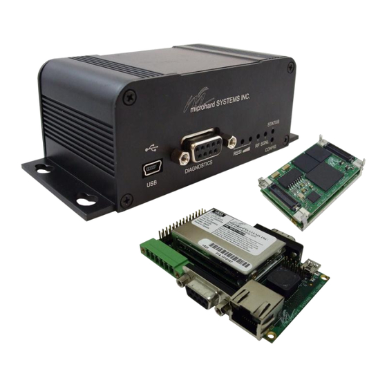
Image 3-3: Nano IP Enclosed Image 3-4: Nano IP Motherboard Image 3-5: Nano IP HV Option © Microhard Systems Inc. CONFIDENTIAL... -
Page 26: Nano Ip Motherboard Mechanical Drawings
Drawing 3-6: Nano IP Motherboard Top View STATUS CONFIG TX RX RSSI Front View Drawing 3-7: Nano IP Motherboard Top View RS485/422 Back View Drawing 3-8: Nano IP Motherboard Top View Notes: The dimension unit is inches. © Microhard Systems Inc. CONFIDENTIAL... -
Page 27: Nano Ip Enclosed Mechanical Drawings
SYSTEMS INC. STATUS DIAGNOSTIC RSSI CONFIG Front View Drawing 3-10: Nano IP Enclosed Front View ANTENNA RS485/422 DATA ETHERNET Back View Image 3-11: Nano IP Enclosed Back View Notes: The dimension unit is inches. © Microhard Systems Inc. CONFIDENTIAL... -
Page 28: Connectors & Indicators
Table 3-3: Diagnostic Port RS232 Pin Assignment CONFIG Button Holding this button depressed while powering-up the Nano IP Series will boot the unit into FLASH FILE SYSTEM RECOVERY mode. The default IP address for system recovery (only - not for normal access to the unit) is static: 192.168.1.39. -
Page 29: Rear
7-30 Vdc. TxA (D-) RxB (R+) RxA (R-) Caution: Using a power supply that Vin - RS485/422 does not provide Vin + proper voltage may damage the modem. Table 3-5: Data RS422/485 / Vin Pin Assignment © Microhard Systems Inc. CONFIDENTIAL... -
Page 30: Hv (Jp3)
3.2.3 Connectors and Indicators 3.2.3.3 HV Motherboard The Nano IP Series HV option provides signal conditioning for Power, RS232, RS485/422, USB, etc and provides a single 28 pin interface, with populating the bulky connectors as seen on the standard motherboard interface. - Page 31 Pull it low upon power up will put the module into recovery mode. 27,28 Positive voltage supply voltage for the module (7-30VDC). Table 3-6: JP3 Nano IP HV Option Pin-out © Microhard Systems Inc. CONFIDENTIAL...
-
Page 32: Operating Modes
4.0 Operating Modes An Nano IP Series may be configured for any operating mode: this is very convenient for pur- poses of sparing and becoming familiar with their configuration menus. 4.1 Master One per network, the source of synchronization for the system. The Master controls the flow of data through the system. -
Page 33: Network Topologies
(noting that the MASTER‘s Unit Address (not visible) is preset, and must remain as, ‗1‘). For a PTP system, RETRANSMISSIONS on a MASTER is not as critical a setting as it is in a Point-to-Multipoint (PMP) system. © Microhard Systems Inc. CONFIDENTIAL... - Page 34 5.0 Network Topologies Example 5.1.1 Image 5A: PTP Example 5.1.1: Master Image 5B: PTP Example 5.1.1: Remote © Microhard Systems Inc. CONFIDENTIAL...
-
Page 35: Point-To-Multipoint (Pmp)
RETRANSMISSIONS are set to 0. Refer to Section 6.1.4 for more information. the configuration of a PMP Master’s There is a REPEATER in this example network, therefore the MASTER‘s ‗Repeater‘ Retransmissions. configuration option is set to Yes. © Microhard Systems Inc. CONFIDENTIAL... - Page 36 MASTER, bypassing the Repeater to the Master. REPEATER altogether. Remote 30‘s ROAMING ADDRESS is set to 1 (the UNIT ADDRESS of the MAS- TER): it will synchronize to, and communicate directly with, the MASTER. © Microhard Systems Inc. CONFIDENTIAL...
- Page 37 5.0 Network Topologies Example 5.2.1 (continued) Image 5E: PMP Example 5.2.1: Remote 20 Each modem in any network must have a unique Unit Address. Image 5F: PMP Example 5.2.1: Remote 30 © Microhard Systems Inc. CONFIDENTIAL...
-
Page 38: Peer-To-Peer (P2P)
A device located at a pump station must communicate bi-directionally with another device at a Remote to another in water tank. The MASTER Nano IP Series must reside in an office at a separate location. P2P mode is transferred via the Master. - Page 39 5.0 Network Topologies Example 5.3.1 (continued) Image 5H: P2P Example 5.3.1: Remote 25 Image 5I: P2P Example 5.3.1: Remote 35 © Microhard Systems Inc. CONFIDENTIAL...
-
Page 40: Everyone-To-Everyone (E2E)
(65535) when in E2E mode. remote units in an E2E network travels to the Master and is then re- broadcast to all other remotes. Image 5J: E2E Example 5.4.1: Master © Microhard Systems Inc. CONFIDENTIAL... - Page 41 UNIT ADDRESS. Each Remote (of the 3 in this example) must have its own unique UNIT AD- DRESS, e.g. 50, 51, and 52. Each unit must have its own unique Unit Address. Image 5K: E2E Example 5.4.1: Remote © Microhard Systems Inc. CONFIDENTIAL...
-
Page 42: Configuration
Systems Inc. DiscoverIP utility and Web Browser application. All configuration of the IP Series is accomplished with a PC. There are no DIP switches to set; switches which may subsequently become inadvertently misadjusted or intermittent. © Microhard Systems Inc. CONFIDENTIAL... -
Page 43: Web User Interface
The Web User Interface (WebUI) is a browser based configuration method that allows a user a graphical interface to configure, test and troubleshoot a Nano IP series unit. Any standard web browser can be used and no additional software is required. Using the Web User Interface a user can: ... -
Page 44: Logon Window
- for one primary reason: security. It is advisable to change the login Password (see Section 6.1.6.1). Do not FORGET the new password as it cannot be recovered. Image 6B: Logon Window With Password Input © Microhard Systems Inc. CONFIDENTIAL... -
Page 45: Welcome Window
6.0 Configuration 6.1.2 Welcome Window The Welcome window displays the specific Nano IP Series‘ name (entered as the Radio Description in the System Configuration menu). This name quickly confirms the ‘identity‘ of the unit being perused and appears in all menu windows. -
Page 46: System Configuration
Series unit will operate at a BRIDGE or a ROUTER. Only a MASTER unit should ever be configured as a router. Bridge Select the System Operation Mode ‗first‘, i.e. prior to configuring Bridge other options within the unit. Router © Microhard Systems Inc. CONFIDENTIAL... - Page 47 Radio Description The Radio Description is simply a convenient identifier for a specific Values Nano IP Series, e.g. Pump Station 5, 123 Main Street, etc. This feature is most welcome when accessing units from afar with large Default is model-dependent networks: a convenient cross-reference for the unit‘s IP address.
- Page 48 NTP Server information has been configured and the service is enabled within the modem (see Section 6.1.3.2 for additional information). Submit Write parameter values into memory. Reset Restore ‗currently‘ modified parameter values to those which were previously written into memory. © Microhard Systems Inc. CONFIDENTIAL...
-
Page 49: Network Configuration
Image 6E: Network Configuration, Top Level Menu The Ethernet MAC address (as displayed above) is that of the ETHERNET interface located at the rear of the Nano IP Series. The Wireless MAC address is for internal purposes. © Microhard Systems Inc. -
Page 50: Local Ip Configuration
6.1.4.1 Local IP Configuration 6.1.4.1.1 Bridge This submenu, along with Radio Configuration settings, are the minimum which must be considered when implementing any Nano IP Series network. It must be determined if the unit is to be either: assigned an IP address (by a DHCP server), or ... - Page 51 (device) portions of an IP address. Values If the Nano IP Series units are integrated into a network which has a The ‗unmasked‘ portion defined gateway, then, as with other hosts on the network, this gateway‘s leaves available IP address will be entered into this field.
- Page 52 6.0 Configuration DHCP Timeout This value determines for how long the Nano IP Series will await to Values receive information from a DHCP server. If this timeout expires, the seconds unit will assign itself a random Class D IP address (and subnet mask) and function simply as a wireless bridge.
-
Page 53: Router
6.1.4.1 Local IP Configuration 6.1.4.1.2 Router If the Nano IP Series unit has been configured as a Router (under the System Configuration menu), the Network Configuration will present some additional options to those presented if the unit was configured as a Bridge. -
Page 54: Wireless Port Ip Configuration
Class C private IP Subnet Mask For a small private network with IP addresses appearing similar to Values 192.168.1.xx (Class C address), the standard 255.255.255.0 subnet mask may be applicable. 255.255.255.0 valid value is specific to the network © Microhard Systems Inc. CONFIDENTIAL... - Page 55 LAN (the wireless subnet) in this field. 0.0.0.0 valid DNS Server IP Soft Buttons Submit Write parameter values into memory. Reset Restore ‗currently‘ modified parameter values to those which were previously written into memory. © Microhard Systems Inc. CONFIDENTIAL...
-
Page 56: Vpn Configuration
Select a unique password of 32 characters maximum, case- Values sensitive. admin 32 characters maximum VPN Admin Repeat Password Enter the same unique password of 32 characters maximum, case-sensitive, which was entered in the preceding/above field. © Microhard Systems Inc. CONFIDENTIAL... -
Page 57: Ntp Server Configuration
IP address or ‘name‘ is entered in the appropriate field. NTP may be used to synchronize the time in the Nano IP Series within a network to a reference time source. Image 6G: Network Configuration, NTP Server Config. Submenu NTP Server Status Note that if NTP Server Status is ENABLED, the ‗Synchronize with... -
Page 58: Dhcp Server Configuration
Nano IP Series units and those IP addressable devices which are connected to them. If this feature is to be utilized, it would be enabled on the Master Nano IP Series unit, noting that such a DHCP Server service must not be enabled on any other IP Series units or devices which reside on the same network segment. -
Page 59: Server Status
Devices on the network, which are intended to receive IP address information from this DHCP Server, must have their local IP settings set for ‗DHCP‘ (as opposed to ‗static‘) © Microhard Systems Inc. CONFIDENTIAL... -
Page 60: Dns Address
Input the IP address of the Domain Name Service (DNS) to be Values www.microhardcorp.com (for example) into the provided by this DHCP Server. URL line of a web 0.0.0.0 browser, the website ‗could not be found‘). Valid DNS IP address © Microhard Systems Inc. CONFIDENTIAL... - Page 61 DELETE soft button used to delete it. Submit Write parameter values into memory. Reset Restore ‗currently‘ modified parameter values to those which were previously written into memory. © Microhard Systems Inc. CONFIDENTIAL...
-
Page 62: Snmp Agent Configuration
6.0 Configuration 6.1.4.4 SNMP Agent Configuration The Nano IP Series may be configured to operate as a Simple Network Management Protocol (SNMP) agent. Network management is most important in larger networks, so as to be able to manage re- sources and measure performance. - Page 63 Effectively a plain-text password mechanism used to weakly authenticate SNMP queries. Being part of the community allows public the SNMP agent to process SNMPv1 and SNMPv2c requests. This community name has only READ priority. character string © Microhard Systems Inc. CONFIDENTIAL...
- Page 64 Authentication Level set to AuthNoPriv or AuthPriv (see above). 00000000 character string V3 Authentication Password SNMPv3 user‘s encryption password. Only valid when V3 User Values Authentication Level set to AuthPriv (see above). 00000000 character string © Microhard Systems Inc. CONFIDENTIAL...
- Page 65 Defines a host IP address where traps will be sent to (e.g. SNMP Values management system PC IP address). 0.0.0.0 applicable host‘s IP Soft Buttons Submit Write parameter values into memory. Reset Restore ‗currently‘ modified parameter values to those which were previously written into memory. © Microhard Systems Inc. CONFIDENTIAL...
-
Page 66: Bridge Configuration
Spanning Tree Protocol Status Selection of STP operational status: On or Off. Values Soft Buttons Submit Write parameter values into memory. Reset Restore ‗currently‘ modified parameter values to those which were previously written into memory. © Microhard Systems Inc. CONFIDENTIAL... -
Page 67: Quality Of Service
6.0 Configuration 6.1.4.6 Quality of Service Quality of Service (QoS) may be applied to various data which enter the Nano IP Series. This section describes configuring QoS for data which enters via the ethernet port. QoS: Quality of Service is applied to networks... - Page 68 Enable and SUBMIT. As ports are defined, the mini window and list boxes (specific to Priority) become populated. To DELETE any defined port, simply select it via the appropriate list box and click the DELETE soft button. © Microhard Systems Inc. CONFIDENTIAL...
-
Page 69: Radio Configuration
Prior to configuration, the network topology must be known (see Section 5.0); the role (operating mode) of the specific Nano IP Series must also be known. Image 6O: Radio Configuration Menu (upper portion) Network Search Mode The above screen capture depicts Radio Configuration menu option with Network Search Mode disabled. - Page 70 With Network Search Mode enabled, Master units with the same authentication key may be found by Remote units even if they have different network names. This feature, which must be enabled on all participating units, allows for ‗roaming‘ between networks. Values Disable Disable Enable © Microhard Systems Inc. CONFIDENTIAL...
-
Page 71: Operation Mode
Network Names. Public Character string Network Name All Nano IP Series in a given network must have the same Network Values Name. This unique network address is not only a security feature default is model- for a particular network, but also allows other networks - with their... - Page 72 Retransmissions value. PTP: Nano IP Series will retransmit to its counterpart only if necessary, and to a maximum number of the value specified in its Retransmissions field. Packet is discarded if retransmis- sions are not successful. Recipients of packets will discard any duplicates.
- Page 73 Master with 65535; in Everyone-to-Everyone, the Destination Address for ALL units is 65535 - the broadcast address - as every unit sends its data to every other unit (through the Master). E2E is a very bandwidth intensive network topology. © Microhard Systems Inc. CONFIDENTIAL...
- Page 74 The Network Profile allows for roaming between networks whereas the Roaming altogether. Address provides for roaming within a network. Values 65535 full roaming 1-254 specific (fixed) unit address (Master or Repeater) with which to associate © Microhard Systems Inc. CONFIDENTIAL...
- Page 75 ‗Repeaters‘ - which This setting applies to the Master only. Values requires 2 Nano IP Series at a ‗Repeater‘ site - eliminates the division of ‗Balanced‘ is the default setting and is typically the best choice for High Throughput bandwidth.
- Page 76 926.250 902.400 914.250 921.750 926.250 902.400 917.250 924.750 926.250 902.400 920.250 906.750 923.250 Table 6-2: Restricted Bands for UA1 at 1.1Mbps Link Rate Values None Zone 1, 2, 3, 4, 5, 6, 7, and 8 © Microhard Systems Inc. CONFIDENTIAL...
-
Page 77: Sleep Mode Config
30-40mA @ 12VDC. Power Shutdown: Timer control shutdown mode. Controlled by Radio Awake Time and Radio Sleep Time parameters. System will reboot when the radio wakes up. Power consumption is about 1mA @ 12 VDC. © Microhard Systems Inc. CONFIDENTIAL... - Page 78 Defines how long the unit will sleep. If set to 0, the radio will not Values (seconds) enter sleep mode. 0 - 65535 Idle Time System idle time before going into sleep mode cycle. Values (seconds) 1 - 65535 © Microhard Systems Inc. CONFIDENTIAL...
-
Page 79: Frequency Restriction
(See Section 6.1.10.4 for a description of the Radio Channel Noise Levels tool.) restriction configured within them. The modem will not allow ‗too many‘ frequencies to be restricted; it requires a certain amount of bandwidth within which to operate to comply with regulations. © Microhard Systems Inc. CONFIDENTIAL... - Page 80 A number of input fields may be used, or a combination of restrictions input in one field. The image below shows an example of configuring an Nano IP Series (with 345kbps as an available Link Rate) with a Link Rate of 345kbps to not operate on channels 1 through 10.
- Page 81 Freq channel 172 = 2401.6 + ((172-1) x 0.400) = 2401.6 + (171 x 0.400) 230kbps 2401.600 .280 = 2401.6 + 68.4 = 2470.000 MHz 345kbps 2401.600 .400 1.2 Mbps 2401.600 1.500 Table 6-4: Channel Spacing 2.4GHz © Microhard Systems Inc. CONFIDENTIAL...
- Page 82 6.0 Configuration Frequency Restriction (continued) With the Nano IP Series having the option of, and configured for, a Link Rate of 1.2Mbps, the Frequency Restriction input format remains the same (as for 345kbps described previously), however, the Channel Number must be reduced by the number of channels restricted, i.e. If...
-
Page 83: Repeater Registration
In order to ensure that generated hopping patterns are orthogonal to each other (thereby minimizing possible interference between network segments), if there is more than 1 Repeater in a network, ALL Repeaters must be registered in EVERY Nano IP Series. The following image depicts an example:... -
Page 84: Com1 And Com2 Configuration
Serial device data may be brought into a LAN network through TCP, UDP, or multicast; it may also exit the Nano IP Series network on another Nano IP‘s serial port. COM1 is a full-featured RS232 interface dedicated to serial data traffic. It supports hardware handshaking. - Page 85 COM1 / DATA. When an interface other than RS232 RS232 is selected, the DE9 port will be inactive. RS485 (Half Duplex) RS422 (Full Duplex) *COM2 / DIAGNOSTIC is RS232 only, 3-wire (TxD, RxD, and SG). © Microhard Systems Inc. CONFIDENTIAL...
- Page 86 ‗None‘. Hardware CTS Framing When CTS Framing is selected, the Nano IP Series uses the CTS Software flow control (XON/XOFF) is not signal to gate the output data on the serial port. Figure 6A below supported.
- Page 87 Values mode (default), the received data will be output promptly from the Seamless Nano IP Series. When set to Seamless, the serial port server will Transparent add a gap between data frames to comply with the MODBUS protocol for example.
-
Page 88: Ip Protocol Config
Default: 60 (seconds) TCP Server: In this mode, the Nano IP Series will not INITIATE a session, rather, it will wait for a Client to request a session of it (it‘s being the Server—it ‗serves‘ a Client). The unit will ‗listen‘... - Page 89 Default: 20001 HTTP uses port 80. UDP Point-to-Multipoint (P): This mode is configured on an Nano IP Series which is to send multicast UDP packets; typically, the MASTER in the Nano IP Series network. Multicast IP Address A valid multicast address this unit uses to send multicast UDP packets upon receiving data from the serial port.
- Page 90 Remote Port The UDP port associated with the Remote IP Address (above). In the case of this ‗Remote‘ being the Master Nano IP Series, the value in this field should match the Listening Port of the Master (see UDP Point-to-Multipoint (P)).
- Page 91 6.0 Configuration IP Protocol Config (continued) SMTP Client: If the Nano IP Series network has Internet access, this protocol may be used to send the data received on the serial port (COM1), in a selectable format (see Transfer Mode (below)), to an e-mail addressee. Both the SMTP Server and the e-mail addressee must be ‗reachable‘...
-
Page 92: Usb Configuration
Provides support for sending and receiving Ethernet frames. Mini USB port can be used as a network interface card. Windows Drivers are available from the Support Desk on the Microhard Systems Inc website. Please register and login into: http://www.microhardcorp.com/support, then locate the drivers in the following location: Support Center »... - Page 93 Image 6X: USB Configuration Data Port Storage Mode: Storage Mode is disable by default. This setting determines device will acts as a USB Mass Storage disk drive with capacity of 2MB. Values Console Mode Data Mode Storage Mode NDIS Mode © Microhard Systems Inc. CONFIDENTIAL...
- Page 94 Preferred DNS Server If applicable, enter the IP address of Preferred DNS Server which exists within the LAN. Alternate DNS Server If applicable, enter the IP address of Alternate DNS Server which exists within the LAN. © Microhard Systems Inc. CONFIDENTIAL...
- Page 95 6.0 Configuration USB Mode System Information Various information is available in the System Information menu that applies to the USB functions of the Nano IP Series. Image 6Y: USB Connection Status USB Port Status Display the Status of USB Port. Configure via USB Configuration menu.
-
Page 96: Security Configuration
6.0 Configuration 6.1.8 Security Configuration There is significant security inherent in the Nano IP‘s proprietary design and technology implementation. There are additional security features available, both as standard and optional items. Image 6W: Security Configuration Menu © Microhard Systems Inc. CONFIDENTIAL... -
Page 97: Admin Password Configuration
Enter a new password for the Admin user. Repeat to ensure the Values intended password was entered and that it was entered correctly. character string Do not forget the admin password as, if lost, it cannot be recovered. admin © Microhard Systems Inc. CONFIDENTIAL... -
Page 98: Upgrade Password Configuration
Image 6Y: Security Config., Upgrade Password Config. Submenu New Password/Repeat Password Enter a new password for the Upgrade user. Repeat to ensure the Values intended password was entered and that it was entered correctly. character string admin © Microhard Systems Inc. CONFIDENTIAL... -
Page 99: Wireless Encryption Configuration
6.0 Configuration 6.1.8.3 Wireless Encryption Configuration There are 2 encryption levels for the Nano IP Series: Medium High Medium and High levels are NOT AVAILABLE FOR EXPORT. High level is optional within North America: Contact Microhard Systems Inc. for more information. -
Page 100: Encryption Type
Compression: Although not encryption per se, applying a compression algorithm to the input data within the transmitting Nano IP Series does require that the corresponding decryption algorithm be applied to the output data of the receiving unit to make it meaningful. - Page 101 128-bit AES. Basically the same configuration as for WEP applies. Input up to 4 very robust symmetric encryption algorithm. unique Keys of 32 characters each. Values Compression WEP 64-bit WEP 128-bit AES 128-bit* AES 256-bit* *optional for North America © Microhard Systems Inc. CONFIDENTIAL...
-
Page 102: Discovery Service Configuration
The configuration selection will determine whether or not this modem may be discovered using the utility, and whether or not changes may be made to the Nano IP Series via the utility. The choice is typically based-upon network security considerations. -
Page 103: Ui (User Interface) Access Configuration
IP address is that of the target device. For security reasons, any or all may be disabled. If the above IP address is that of an Nano IP Series accessible via the network, the user will arrive at the unit‘s LogOn window. -
Page 104: Authentication Configuration
6.0 Configuration 6.1.8.6 Authentication Configuration There are two methods whereby a user may be authenticated for access to the Nano IP Series: Local Using the Admin or Upgrade access and associated passwords - the authentication is done ‗locally‘ within the IP Series, and ... - Page 105 RADIUS User Name from your RADIUS Server Administrator.) nosecret Repeat RADIUS Secret See above. Re-enter RADIUS Secret in this field. Values Specific RADIUS Server secret nosecret RADIUS Timeout Amount of time to wait for RADIUS authentication. Values 1-65535 seconds © Microhard Systems Inc. CONFIDENTIAL...
-
Page 106: Firewall Configuration
Configuration is specifically for configuring the Nano IP‘s User Interface and related protocols. Image 6AE: Security Config. Menu, Firewall Configuration Submenu Firewall Status Disabled by default. When enabled, the firewall settings are in Values effect. Disable Enable © Microhard Systems Inc. CONFIDENTIAL... -
Page 107: Policies
Select the zone which is the intended destination of the data traffic. Values WAN applies to the wired connection and LAN to the wireless, on all Nano IP Series units, whether a Master, Repeater, or Remote. © Microhard Systems Inc. CONFIDENTIAL... - Page 108 List of current policies. Use the Edit, Delete, Up, Down to modify the polices. Use Submit to write policies to Nano IP and make active, use the Reset button to revert back to the policies currently stored in the Nano IP. © Microhard Systems Inc. CONFIDENTIAL...
-
Page 109: Rules
Rules take precedence over Policies. They are configured to ‗fine tune‘ firewall settings. Image 6AG: Firewall Configuration, Rules Config. Submenu Action Define the action which is to be taken by the defined rule. Values ACCEPT ACCEPT+>future NONAT>future DROP REJECT DNAT SAME>future REDIRECT>future CONTINUE>future QUEUE>future © Microhard Systems Inc. CONFIDENTIAL... - Page 110 If a valid IP address is specified, the action will apply against that Values address; otherwise, leaving the default value of 0.0.0.0 in this field results in the action applying to all destination IP addresses. 0.0.0.0 valid IP address © Microhard Systems Inc. CONFIDENTIAL...
- Page 111 This field is configured if defining a Custom Service (ref. Select Values Service field). TCP:SYN ICMP IPP2P IPP2P:UDP IPP2P:all Comment This is simply a field where a convenient reference or description Values may be added to the rule. Rule 1 descriptive comment © Microhard Systems Inc. CONFIDENTIAL...
-
Page 112: Port Forwarding
Enter the IP address of the intended internal (i.e. on LAN side of IP Values Series unit configured as a Router) server. 192.168.2.5 valid IP address Internal Port Target port number of internal server. Values valid port number © Microhard Systems Inc. CONFIDENTIAL... - Page 113 Port number of incoming request (from WAN-side device). Values valid port number Comment This is simply a field where a convenient reference or description Values may be added to the rule. Forward 1 descriptive comment © Microhard Systems Inc. CONFIDENTIAL...
-
Page 114: Mac List
LAN MAC List Status Enable or disable the LAN MAC list. List takes precedence over Values Rules. Disable Enable MAC Address Specify the MAC Address to be added to the list. Values 00:00:00:00:00:00 valid MAC address © Microhard Systems Inc. CONFIDENTIAL... - Page 115 6.0 Configuration Disposition Determines the action to be taken on data traffic associated with Values the specified MAC address. ACCEPT DROP REJECT Interface Select which interface the defined MAC address is connected to. Values © Microhard Systems Inc. CONFIDENTIAL...
-
Page 116: Blacklist
Disable Enable IP/Subnet or MAC Address Enter the IP/Subnet or MAC address of the device to be blacklisted. Values All data traffic associated with this address will be blocked. 192.168.1.5 valid IP address © Microhard Systems Inc. CONFIDENTIAL... -
Page 117: Reset Firewall To Factory Default
6.0 Configuration 6.1.8.7.6 Reset Firewall to Default This menu provides a soft button which, when selected, will reset the firewall settings to factory defaults. Image 6AK: Reset Firewall to Default © Microhard Systems Inc. CONFIDENTIAL... -
Page 118: System Information
Detailed statistical and status information about Ethernet Packets, Radio, COM (1/2) and USB ports can be found in the submenu‘s accessed from this screen. If desired, your browsers‘ Refresh button (F5) may be used to initiate a ‗manual‘ refresh. © Microhard Systems Inc. CONFIDENTIAL... - Page 119 The Transmit Carrier count relates to carrier sense errors. Image 6AM: System Information Menu, Ethernet Packet Statistics © Microhard Systems Inc. CONFIDENTIAL...
- Page 120 The Error counts reflect those having occurred on the wireless link. Lost Sync indicates how many times the Nano IP being viewed has lost synchronization with the Master Nano IP. © Microhard Systems Inc. CONFIDENTIAL...
- Page 121 Image 6AO: System Information Menu, COM1 Connection Status The other displayed parameters are not all applicable. Of most use are the transmitted and received bytes/packets: these will indicate if data is coming into and out of the RS-232 port. © Microhard Systems Inc. CONFIDENTIAL...
- Page 122 6.0 Configuration COM2 (Diagnostic) Connection Status This window displays information related to the COM2 (Diagnostic) port located on the front of the Nano IP Series. COM2 Port Status Disabled (for ‗data‘ traffic) by default. Being ‘disabled‘ enables the port to be used for the Text User Interface.
- Page 123 Image 6AP: System Information Menu, USB Connection Status The other displayed parameters are not all applicable. Of most use are the transmitted and received bytes/packets: these will indicate if data is coming into and out of the USB port. © Microhard Systems Inc. CONFIDENTIAL...
-
Page 124: System Tools
This menu is used for performing system maintenance (upgrades), rebooting the system (locally or remotely), resetting the system to factory default settings, and for monitoring the radio channel noise within the operating frequency range of the Nano IP Series. Image 6AQ: System Tools Menu - Master ©... -
Page 125: System Maintenance (Firmware Upgrade)
(firmware). Select the Browse button to locate the upgrade file provided my Microhard Systems. Using the Erase Settings checkbox tells the Nano IP not to store the current configuration settings, therefore once the upgrade process is complete the unit will have factory de-... -
Page 126: Reboot System
6.1.10.3 System Tools > Reset System to Default There are many configuration options for the Nano IP Series units. Should a unit reach a state where it is not performing as desired and it is possible that one or many configuration options may be improperly set, resetting the system to default - essentially back to factory settings - will enable one to take a fresh start in reprogramming the unit. -
Page 127: Radio Channels Noise Level
6.1.10.4 System Tools > Radio Channels Noise Level This tool may be used to measure and observe the mean (average) and peak (max) noise levels in the operating frequency range of the Nano IP Series. When a Radio Channels Noise Level measurement is taken, the Nano IP goes ‗offline‘... -
Page 128: Network Discovery
Remote Sleep Control allows basic remote configuration of the sleep properties of remote units. Any sleep configuration parameters sent from a Master unit will overwrite any existing sleep settings in the remote unit. Image 6AX: Remote Sleep Control © Microhard Systems Inc. CONFIDENTIAL... - Page 129 Resets values shown in the boxes above to the values stored in the Master unit. View Unit Sleep Status Only: Retrieves the sleep settings stored on the remote unit. Auto Refresh: Forces the browser to refresh. © Microhard Systems Inc. CONFIDENTIAL...
-
Page 130: Local Power Saving (Master)
Defines how long the radio will keep awake. If set to 0, the radio will Values (seconds) not wakeup until received data from the port configured in the Power Saving Mode (Serial or Ethernet ports). 0 - 65535 © Microhard Systems Inc. CONFIDENTIAL... -
Page 131: Logout
0 - 65535 6.1.10.8 Logout The Logout menu informs the user how to log out of the Web User Interface, by closing the current web browser session. Image 6BB: Logout Window © Microhard Systems Inc. CONFIDENTIAL... -
Page 132: Text User Interface
115200bps, 8 data bits, no parity, and 1 stop bit. Flow control should be set to ‗none‘. apply power to the Nano IP Series and wait approximately 1 minute for the system to load - you will observe various text appearing in the terminal program window. Once the Nano IP... - Page 133 Web UI. There are some subtle differences in configuring the IP Series using the Text UI. The following steps pertaining to configuring the Radio portion of the unit will highlight those differences: © Microhard Systems Inc. CONFIDENTIAL...
- Page 134 Select ‗C‘ on the Main Menu to be directed to the Radio Menu (see below): Image 6BE: Text User Interface, Radio (Configuration) Menu Select ‗I‘ to change the Network Type. The following will appear: Image 6BF: Text User Interface, Radio Menu, Network Type © Microhard Systems Inc. CONFIDENTIAL...
- Page 135 As can be seen in the preceding screen captures, the [Esc] key is used to ‗back up‘ to the previous menu. When at the Main Menu, the ‗Q‘ may be used to Quit the Text UI: the IP Series will display the login prompt. © Microhard Systems Inc. CONFIDENTIAL...
-
Page 136: Installation
Throughput experienced personnel. The Nano IP Series is capable of significant data throughput. The network topology has an ef- fect on how this available throughput is ‗shared‘ between all nodes on the network. Distance The physical distance between the Nano IP Series dictates such things as required antenna performance and heights, and whether or not a Repeater(s) is required. - Page 137 (receive sensitivity). Being that the Nano IP Series performs to exacting specifications, the overall deployment should be such that the modems may be utilized to their full potential to pro- vide a reliable and robust communications link.
-
Page 138: Path Calculation
Tx power = 30dBm Tx antenna gain = 6dBi System Gain = 30+(6-2)+(3-2) Tx cable/connector loss = 2dB +105 Rx antenna gain = 3dBi = 30+4+1+105 Rx cable/connector loss = 2dB = 140dB. Rx sensitivity = -105dBm © Microhard Systems Inc. CONFIDENTIAL... -
Page 139: Installation Of Antenna System Components
Never work on an antenna system when there is lightning in the area. © Microhard Systems Inc. CONFIDENTIAL... -
Page 140: Antennas
Care must also be taken to affix the connectors properly - using the proper crimping tools - and to weatherproof them. © Microhard Systems Inc. CONFIDENTIAL... -
Page 141: Surge Arrestors
Paging towers and cellular base stations in close proximity to the Nano IP antenna can desensitize the receiver. Microhard Systems Inc.‘s exter- nal cavity filter eliminates this problem. The filter has two N-female connectors and should be connected inline at the interface to the RF equipment. -
Page 142: Appendix A: Discoverip Utility
In the sample, there is three Nano IP units connected to same network to which the PC is con- configuring the Nano IP nected. Activating the ‘Discover New‘ button results in the Nano IP Series being discovered by Series to be, or not be, ‗discoverable‘. - Page 143 Properties) are suited to establishing a connection with the Nano IP Series. Image A3: Select Target Nano IP Series Selecting either method (above) will launch the PC‘s web browser to the IP Series Logon win- dow. If it would be necessary but is not convenient to change the TCP/IP Properties settings on the...
-
Page 144: Appendix B: Upgrade Procedure (Dos Prompt)
Appendix B: Upgrade Process (DOS Prompt) © Microhard Systems Inc. CONFIDENTIAL... - Page 145 Appendix B: Upgrade Procedure (DOS Prompt) © Microhard Systems Inc. CONFIDENTIAL...
-
Page 146: Appendix C: Rs485 Wiring
Figure C1 illustrates a typical 2-wire RS485 wiring configuration. The cable pair is shared for both transmit and receive data: it is very important that the Nano IP Series seize control of the line at the proper time when it is to transmit data. -
Page 147: Appendix D: Approved Antennas
6dBd, 900 MHz Omni Directional Antenna Bluewave, RPTNC Pigtail WARNING: Changes or modifications not expressly approved by Microhard Systems Inc. could void the user’s authority to operate the equipment. This device has been tested with MCX and Reverse Polarity SMA connectors with the antennas listed in Appendix A When integrated in OEM prod- ucts, fixed antennas require installation preventing end-users from replacing them with non- approved antennas. -
Page 148: Appendix E: Nano Ip Oem Layout
Appendix E: Nano IP OEM Layout (Optional - Nano IP) © Microhard Systems Inc. CONFIDENTIAL... -
Page 149: Appendix F: Serial Interface
(DCE); the module transmits data on the RX line, and receives on TX. ―DCE‖ and ―module‖ are often synonymous since a module is typically a DCE device. ―DTE‖ is, in most applications, a device such as a host microprocessor. © Microhard Systems Inc. CONFIDENTIAL... -
Page 150: Appendix G: Customer Interface Schematic
Appendix G: Nano IP Motherboard Schematic (Page 1 of 3) © Microhard Systems Inc. CONFIDENTIAL... - Page 151 Appendix G: Nano IP Motherboard Schematic (Page 2 of 3) © Microhard Systems Inc. CONFIDENTIAL...
- Page 152 Appendix G: Nano IP Motherboard Schematic (Page 3 of 3) © Microhard Systems Inc. CONFIDENTIAL...
-
Page 153: Appendix H: Firmware Upgrade / Recovery
Ø Change transfer protocol to *BINARY* mode; Ø Push package upgrade file into the system with ―put‖ command; Ø Package upgrade takes more than 2 minutes to complete. Ø The unit automatically reboots after the recovery procedure is completed © Microhard Systems Inc. CONFIDENTIAL... - Page 154 150 Country Hills Landing NW Calgary, Alberta Canada T3K 5P3 Phone: (403) 248-0028 Fax: (403) 248-2762...
Need help?
Do you have a question about the Nano IP Series and is the answer not in the manual?
Questions and answers