
Related Manuals for Microhard Systems IP-921


Summary of Contents for Microhard Systems IP-921
- Page 1 Operating Manual IP-921 900MHz Wireless Ethernet Bridge/Serial Gateway Document: IP9xx Series.OM.F200.Rev3.3wc May 2011...
- Page 2 Warranty Microhard Systems Inc. warrants that each product will be free of defects in material and workmanship for a period of one (1) year for its products. The warranty commences on the date the product is shipped by Microhard Systems Inc. Microhard Systems Inc.’s sole liability and responsibility under this warranty is to repair or replace any product which is returned to it by the Buyer...
- Page 3 Highlights a key feature, point, or step which is noteworthy. Keeping these in mind will simplify or enhance device usage. An idea or suggestion to improve efficiency or enhance usefulness. Information Information regarding a particular technology or concept. © Microhard Systems Inc. CONFIDENTIAL...
- Page 4 This device can only be used with Antennas listed in Appendix D. Please contact Microhard Systems Inc. if you need more information or would like to order an antenna. WARNING MAXIMUM EIRP FCC Regulations allow up to 36dBm Effective Isotropic Radiated Power (EIRP).
- Page 5 Division 2 approved, and therefore, power must be supplied to the units using the screw-type or locking type connectors supplied from Microhard Systems Inc. and a Class 1 Division 2 power source within your panel. If you are unsure as to the specific wiring and installation guidelines for Class 1 Division 2 codes, contact CSA International.
-
Page 6: Revision History
Based on: Ref. 6.1.2 FPGA Version 1R4, Software Version 2.0.0; Ref. 6.1.8/Radio Info. Version 3.1092ip Revision 2.0 November 20, 2006 Based on: Ref. 6.1.2 FPGA Version 1R4, Software Version 1.3.4; Ref. 6.1.8/Radio Info. Version 3.1082ip © Microhard Systems Inc. CONFIDENTIAL... -
Page 7: Table Of Contents
6.1.4 Network Configuration ....................47 6.1.4.1 Local IP Configuration ..................48 6.1.4.1.1 Bridge .................... 48 6.1.4.1.2 Router ................... 52 6.1.4.1.2.1 Wireless Port IP Configuration ......53 6.1.4.1.2.2 VPN Configuration ..........53 6.1.4.2 NTP Server Configuration ................57 continued... © Microhard Systems Inc. CONFIDENTIAL... - Page 8 6.2 Text User Interface ........................151 7.0 Installation 7.1 Path Calculation ........................158 7.2 Installation of Antenna System Components ................159 7.2.1 Antennas ........................160 7.2.2 Coaxial Cable ....................... 161 7.2.3 Surge Arrestors ......................161 7.2.4 External Filter ....................... 162 © Microhard Systems Inc. CONFIDENTIAL...
- Page 9 Appendix B: Upgrade Procedure (DOS Prompt) ................165 Appendix C: RS485 Wiring ......................167 Appendix D: Approved Antennas ....................168 Appendix E: Mounting Dimensions ....................169 Appendix F: Serial Interface ......................170 Appendix G: SIP921 Customer Interface Schematic ..............171 © Microhard Systems Inc. CONFIDENTIAL...
-
Page 10: Overview
Key performance features of the IP Series include: 920-928MHz, which is license-exempt within North America, may need to be factory-configured differently for other areas: contact Microhard Systems Inc. © Microhard Systems Inc. CONFIDENTIAL... -
Page 11: Specifications
IP9xx Series 1.0 Overview 1.2 Specifications Refer to the Specifications Sheet supplied to you for your par- ticular model. © Microhard Systems Inc. CONFIDENTIAL... - Page 12 Supporting co-located independent networks and with the ability to carry both serial and IP traffic, the IP Series supports not only net- work growth, but also provides the opportunity to migrate from asynchronous serial devices connected today to IP-based devices in the future. © Microhard Systems Inc. CONFIDENTIAL...
-
Page 13: Quick Start
8 seconds - the SYS line. LED will initially blink, then be on solid, and then the unit will reset. Refer to Section 6.1.1 re LogOn. Note: Some OEM customers will have their specific factory defaults loaded. continued... © Microhard Systems Inc. CONFIDENTIAL... - Page 14 TX LED should be ON or flashing. With the PC connected to one of the IP Series units, en- ter the IP Address of ‗the other‘ unit: its LogOn window should appear via the wireless connection. © Microhard Systems Inc. CONFIDENTIAL...
-
Page 15: Text User Interface Method
115200bps, 8 data bits, no parity, 1 stop bit, and no flow source. control. Activate the HyperTerminal connection. A login prompt will appear. Enter admin. At the password prompt, enter admin. continued... © Microhard Systems Inc. CONFIDENTIAL... - Page 16 Remove the connection from the MASTER IP Series‘s COM2 port and move it to the other IP Series. Press [Enter] A login prompt will appear. Enter admin. At the password prompt, enter admin. continued... © Microhard Systems Inc. CONFIDENTIAL...
- Page 17 With these two IP Series on a test bench, and configured as per the preceding, a wireless link will be present between the two units. This may be confirmed by noting that the RSSI (3 front panel LEDs) are illuminated. Next, the ethernet connections will be made. continued... © Microhard Systems Inc. CONFIDENTIAL...
- Page 18 (indicating proper cabling) and the amber (ACTIVITY LED) should also be flickering—indicating DATA traffic at the ETHERNET connector. If using Windows XP, the firewall function could inhibit desired data traffic. Anti-virus software may also have a negative impact. © Microhard Systems Inc. CONFIDENTIAL...
-
Page 19: Hardware Features
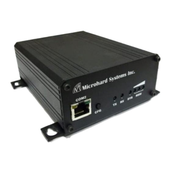
Front View of IP Series On the front of the IP Series are, from left to right: COM2 Port (DCE) CFG pushbutton TX LED RX LED SYS LED RSSI LEDs (3) © Microhard Systems Inc. CONFIDENTIAL... - Page 20 CFG Button for 8 seconds will result in FACTORY DEFAULTS being restored, including a static IP address of 192.168.1.254. This IP address is useable in a Web Browser for accessing the Web User Interface. © Microhard Systems Inc. CONFIDENTIAL...
-
Page 21: Rear
1 Data Carrier Detect 2 Receive Data 3 Transmit Data 4 Data Terminal Ready 5 Signal Ground 6 Data Set Ready 7 Request To Send 8 Clear To Send Table 3B: COM1 (RS-232) Pin Assignment © Microhard Systems Inc. CONFIDENTIAL... - Page 22 Antenna Connector The IP Series uses a reverse polarity TNC (RP-TNC) connector. Microhard Systems Inc. can provide external cabling and antennas suited to a variety of applications where the standard rubber ducky antenna is not adequate. Refer to Appendix D for a listing of approved antennas.
-
Page 23: Ip9Xx Indicators
Upon initial application of power the SYS LED will be illuminated for recovery procedure. recovery procedure. approximately 20 seconds, after which time it will being to blink slowly (loading) for an additional 25 seconds, then stay ON ‗solid‘ (indicating it has achieved its specific operational status). © Microhard Systems Inc. CONFIDENTIAL... -
Page 24: Rear
Activity LED to confirm that proper patchcable types are Activity LED (Green) being used. Located at top/right of the ETHERNET connector, illuminates when there is data activity present on the ethernet interface. © Microhard Systems Inc. CONFIDENTIAL... -
Page 25: Sip921 Connections
RS232/485/422 interfaces. Status/Diagnostic output signals for system status, RSSI, Ethernet etc. The Pin-out and signal descriptions are described on the following pages. An example customer interface schematic can be found in Appendix G. © Microhard Systems Inc. CONFIDENTIAL... -
Page 26: Sip921 Pin-Out Description
The corner pins (1, 2, 51, and 52) are printed directly upon it for convenient reference. Inputs and outputs are TTL Level unless otherwise specified. A full description of the various pin connections and functions is provided on the pages that follow. © Microhard Systems Inc. CONFIDENTIAL... - Page 27 DTR0 29 Data Port. Data Terminal Ready. Active low input. DSR0 30 Data Port. Data Set Ready. Active low output. 31-32 Ground reference for logic, radio, and I/O pins Table 3E: SIP921 Pin-Out Description © Microhard Systems Inc. CONFIDENTIAL...
- Page 28 Loading/Upgrading = Slow Blink (1 every 2s) TX LED 50 Output indicates module is transmitting data over the RF channel. RX LED 52 Output indicates receive and synchronization status. Table 3E: SIP921 Pin-Out Description (continued) © Microhard Systems Inc. CONFIDENTIAL...
-
Page 29: Operating Modes
Endpoint/node within a network to which a local device is attached. or Remote - i.e. non-Master Communicates with Master either directly or through one or more Repeaters. See Sections 5.3 and 5.4 for information regarding ‗Slave-to-Slave‘ communications. © Microhard Systems Inc. CONFIDENTIAL... -
Page 30: Network Topologies
MASTER‘s Unit Address (not visible) is preset, and must remain as, ‗1‘). For a PTP system, RETRANSMISSIONS on a MAS- TER is not as critical a setting as it is in a Point-to- Multipoint (PMP) system. © Microhard Systems Inc. CONFIDENTIAL... - Page 31 IP9xx Series 5.0 Network Topologies Image 5A: PTP Example 5.1.1: Master Example 5.1.1 Image 5B: PTP Example 5.1.1: Remote © Microhard Systems Inc. CONFIDENTIAL...
-
Page 32: Point-To-Multipoint (Pmp)
6.1.4 for more information. P M P M a s t e r ‘ s Retransmissions. There is a REPEATER in this example network, there- fore the MASTER‘s ‗Repeater‘ configuration option is set to Yes. © Microhard Systems Inc. CONFIDENTIAL... - Page 33 (and pass data directly to) the MASTER, bypassing REPEATER Remote 30‘s ROAMING ADDRESS is set to 1 (the altogether. UNIT ADDRESS of the MASTER): it will synchronize to, and communicate directly with, the MASTER. © Microhard Systems Inc. CONFIDENTIAL...
- Page 34 IP9xx Series 5.0 Network Topologies Example 5.2.1 (continued) Image 5E: PMP Example 5.2.1: Remote 20 Each modem in any network must have a unique Unit Address. Image 5F: PMP Example 5.2.1: Remote 30 © Microhard Systems Inc. CONFIDENTIAL...
-
Page 35: Peer-To-Peer (P2P)
The MASTER IP Series must reside in an office at a separate location. Image 5G: P2P Example 5.3.1: Master All IP Series within a particular network must be configured to have the same Network Type. continued... © Microhard Systems Inc. CONFIDENTIAL... - Page 36 IP9xx Series 5.0 Network Topologies Example 5.3.1 (continued) Image 5H: P2P Example 5.3.1: Remote 25 Image 5I: P2P Example 5.3.1: Remote 35 © Microhard Systems Inc. CONFIDENTIAL...
- Page 37 1 Master and 3 remote units must all communicate with each other. other remotes. Image 5J: E2E Example 5.4.1: Master There is no DESTINATION UNIT configuration option as the DESTINATION is predefined to be the broadcast address (65535) when in E2E mode. © Microhard Systems Inc. CONFIDENTIAL...
-
Page 38: Everyone-To-Everyone (E2E)
The Remotes will all be configured as per the above screen cap- ture, with the exception of the UNIT ADDRESS. Each Remote (of the 3 in this example) must have its own unique UNIT ADDRESS, e.g. 50, 51, and 52. © Microhard Systems Inc. CONFIDENTIAL... -
Page 39: Configuration
HyperTerminal), or rear ETHERNET (RJ45) port, ethernet crossover cable, and PC running Microhard Systems Inc. DiscoverIP util- ity and Web Browser application. All configuration of the IP Series is accomplished with a PC. There are no DIP switches to set; switches which may subsequently be- come inadvertently misadjusted or intermittent. -
Page 40: Web User Interface
The modem will arrive from factory with DHCP run Microhard Systems Inc. DiscoverIP Utility on the PC (see enabled and a unique random Appendix A for complete details on this convenient utility) Class D IP address. within the DiscoverIP Utility window, click on the desired unit‘s... -
Page 41: Logon Window
(discussed further along in this section), but once changed, if forgotten, may not be recovered. It is advisable to change the login Password (see Section 6.1.6.1). Do not FORGET the new password as it cannot be recovered. © Microhard Systems Inc. CONFIDENTIAL... - Page 42 - particularly once the unit is deployed in the field - for one primary reason: security. Image 6B: Logon Window With Password Input Soft Buttons Inputs the selected values into the IP Series for processing. Cancel Cancels the logon process. © Microhard Systems Inc. CONFIDENTIAL...
-
Page 43: Welcome Window
Software Version - this software resides on the motherboard and is also referred to as the unit‘s ‘firmware‘ FPGA Version - Field Programmable Gate Array - resides on the motherboard and relates to the interface between the motherboard and radio module © Microhard Systems Inc. CONFIDENTIAL... -
Page 44: System Configuration
Series unit will operate at a BRIDGE or a ROUTER. Only a MASTER unit should ever be configured as a router. Select the System Operation Mode ‗first‘, i.e. prior to configuring other options within the unit. Values Bridge Bridge Router © Microhard Systems Inc. CONFIDENTIAL... - Page 45 The calendar date may be entered in this field. Note that the entered value is lost should the IP Series lose power for some reason. Values 11:27:28 (varies) valid time values, where = 2-digit hours = 2-digit minutes = 2-digit seconds © Microhard Systems Inc. CONFIDENTIAL...
- Page 46 (see Section 6.1.3.2 for additional information). Submit Write parameter values into IP Series memory. Reset Restore ‗currently‘ modified parameter values to those which were previously written into IP Series memory. © Microhard Systems Inc. CONFIDENTIAL...
-
Page 47: Network Configuration
Image 6E: Network Configuration, Top Level Menu The Ethernet MAC address (as displayed above) is that of the ETHERNET interface located at the rear of the IP Series. The Wireless MAC address is for internal purposes. © Microhard Systems Inc. CONFIDENTIAL... -
Page 48: Local Ip Configuration
IP Address Mode If ‗static‘ is selected, the three following fields (see Image 6F) are to be manually populated with values which will suit the network/ devices to which the IP Series is connected. continued... © Microhard Systems Inc. CONFIDENTIAL... - Page 49 255.255.255.0 information required valid value is specific to the identify the various devices network on the subnet. © Microhard Systems Inc. CONFIDENTIAL...
- Page 50 This value determines for how long the IP Series will await to receive information from a DHCP server. If this timeout expires, the unit will assign itself a random Class D IP address (and subnet mask) and function simply as a wireless bridge. Values seconds 1-65535 © Microhard Systems Inc. CONFIDENTIAL...
- Page 51 Values 0.0.0.0 valid DNS Server IP address Soft Buttons Submit Write parameter values into IP Series memory. Reset Restore ‗currently‘ modified parameter values to those which were previously written into IP Series memory. © Microhard Systems Inc. CONFIDENTIAL...
-
Page 52: Router
‗wired‘ connection of the MASTER unit. There are two other options to be discussed further on the following pages: Wireless Port IP Configuration VPN Configuration © Microhard Systems Inc. CONFIDENTIAL... -
Page 53: Wireless Port Ip Configuration
IP Subnet Mask For a small private network with IP addresses appearing similar to 192.168.1.xx (Class C address), the standard 255.255.255.0 subnet mask may be applicable. Values 255.255.255.0 valid value is specific to the network © Microhard Systems Inc. CONFIDENTIAL... - Page 54 Values 0.0.0.0 valid DNS Server IP address Soft Buttons Submit Write parameter values into IP Series memory. Reset Restore ‗currently‘ modified parameter values to those which were previously written into IP Series memory. © Microhard Systems Inc. CONFIDENTIAL...
- Page 55 VPN Status Enable (default) enables the service; Disable disables it. on the LAN. Values Enable Enable Disable VPN Admin Password Select a unique password of 32 characters maximum, case- sensitive. Values admin 32 characters maximum © Microhard Systems Inc. CONFIDENTIAL...
- Page 56 Values admin 32 characters maximum Soft Buttons Submit Write parameter values into IP Series memory. Reset Restore ‗currently‘ modified parameter values to those which were previously written into IP Series memory. © Microhard Systems Inc. CONFIDENTIAL...
-
Page 57: Ntp Server Configuration
Note that if NTP Server Status is ENABLED, the ‗Synchronize with NTP Server‘ soft button on the System Configuration menu will be available for use. Leave as DISABLED (default) if a server is not available. Values Disable Disable Enable © Microhard Systems Inc. CONFIDENTIAL... - Page 58 NTP server IP address or ‗name‘ Soft Buttons Submit Write parameter values into IP Series memory. Reset Restore ‗currently‘ modified parameter values to those which were previously written into IP Series memory. © Microhard Systems Inc. CONFIDENTIAL...
-
Page 59: Dhcp Server Configuration
MAC address: the DHCP Server ensures that a specified IP address is assigned to a specific MAC address (hence, device - ei- ther an IP Series or other IP-based device attached to the LAN). © Microhard Systems Inc. CONFIDENTIAL... - Page 60 DHCP SERVER service. Values (The Server issues address information at the Disable request of a DHCP Client, w h i c h r e c e i v e s t h e Disable information.) Enable © Microhard Systems Inc. CONFIDENTIAL...
- Page 61 This is the starting (‗lower boundary‘) IP address of the range of IP addresses (also known as ‘IP address pool‘) to be issued by the DHCP Server to the applicable devices on the network. Values 192.168.2.5 IP address as per above © Microhard Systems Inc. CONFIDENTIAL...
- Page 62 Windows network: process known name resolution. It automatically Values updates, which is particularly important on a network where 0.0.0.0 DHCP is in use. Valid WINS IP address © Microhard Systems Inc. CONFIDENTIAL...
- Page 63 Starting Address and Ending Address parameters input previously - which is to be ‗bound‘ to the MAC address identified in the New Binding MAC field (described above). Values 0.0.0.0 IP address from within range identified in Starting Address and Ending Address fields © Microhard Systems Inc. CONFIDENTIAL...
- Page 64 DELETE soft button used to delete it. Submit Write parameter values into IP Series memory. Reset Restore ‗currently‘ modified parameter values to those which were previously written into IP Series memory. © Microhard Systems Inc. CONFIDENTIAL...
-
Page 65: Snmp Agent Configuration
SNMPv3 adds strong security features including encryption; a shared password key is utilized. Secure device monitoring over the Internet is possible. In addition to the commands noted as supported above, there is a command to synchronize with a remote management sta- tion. © Microhard Systems Inc. CONFIDENTIAL... - Page 66 Read Only Community Name Effectively a plain-text password mechanism used to weakly authenticate SNMP queries. Being part of the community allows the SNMP agent to process SNMPv1 and SNMPv2c requests. This community name has only READ priority. continued... © Microhard Systems Inc. CONFIDENTIAL...
- Page 67 Write priority. If Read Only is selected, the SNMPv3 user may only read information; if Read Write is selected, the SNMPv3 user may read and write (set) variables. Values Read Only Read Only Read Write © Microhard Systems Inc. CONFIDENTIAL...
- Page 68 Authentication Level set to AuthNoPriv or AuthPriv (see above). Values 00000000 character string V3 Authentication Password SNMPv3 user‘s encryption password. Only valid when V3 User Authentication Level set to AuthPriv (see above). Values 00000000 character string © Microhard Systems Inc. CONFIDENTIAL...
- Page 69 V1&V2&V3 Traps Auth Failure Traps If enabled, an authentication failure trap will be generated upon authentication failure. Values Disable Disable Enable Trap Community Name The community name which may receive traps. Values TrapUser character string © Microhard Systems Inc. CONFIDENTIAL...
- Page 70 PC IP address). Values 0.0.0.0 applicable host‘s IP address Soft Buttons Submit Write parameter values into IP Series memory. Reset Restore ‗currently‘ modified parameter values to those which were previously written into IP Series memory. © Microhard Systems Inc. CONFIDENTIAL...
-
Page 71: Bridge Configuration
Selection of STP operational status within the IP Series: On or Off. Values Soft Buttons Submit Write parameter values into IP Series memory. Reset Restore ‗currently‘ modified parameter values to those which were previously written into IP Series memory. © Microhard Systems Inc. CONFIDENTIAL... -
Page 72: Quality Of Service
If Enabled, the defined protocols and ports will have the QoS service applied to them. Values Disable Disable Enable To define particular ports, protocol, and priority to be assigned, see the example of such a configuration exercise on the following page. © Microhard Systems Inc. CONFIDENTIAL... - Page 73 Priority. To apply the configuration: select Enable and SUBMIT. As ports are defined, the mini window and list boxes (specific to Priority) become populated. To DELETE any defined port, simply select it via the appropriate list box and click the DELETE soft button. © Microhard Systems Inc. CONFIDENTIAL...
-
Page 74: Vlan
VLAN ID 3. It can be passed or dropped by itself, depending on the VLAN setting on the bridge. You can only telnet or web access the unit by VLAN 3 in this case. © Microhard Systems Inc. CONFIDENTIAL... - Page 75 The default value is disable. Disable / enable Management VLAN (VLAN ID) Once VLAN us enabled, it uses a default value of 1 for the Values Native VLAN for management purposes. © Microhard Systems Inc. CONFIDENTIAL...
- Page 76 VLAN ID. Filter Filter: Passes data along that has the current VLAN ID Exclude Tag: Tags untagged data with the current VLAN ID Exclude: Blocks any data with the current VLAN ID © Microhard Systems Inc. CONFIDENTIAL...
-
Page 77: Radio Configuration
Network Search Mode The above screen capture depicts Radio Configuration menu option with Network Search Mode disabled. On the following page, the screen capture shows what configuration options are available when Network Search Mode is enabled. continued... © Microhard Systems Inc. CONFIDENTIAL... - Page 78 With Network Search Mode enabled, Master units with the same authentication key may be found by Remote units even if they have different network names. This feature, which must be enabled on all participating units, allows for ‗roaming‘ between networks. Values Disable Disable Enable © Microhard Systems Inc. CONFIDENTIAL...
- Page 79 5.3, 5.4). Values Remote Master Repeater Remote Authentication Key The Authentication Key is used to define the network search group: Masters with the same key can be found by Remotes with different Network Names. continued... © Microhard Systems Inc. CONFIDENTIAL...
- Page 80 This is the RF communications Link Rate. A lower link rate offers better receive sensitivity performance; a higher link rate, better throughput. All IP Series in a network must use the same Link Rate. Values default value and available rate(s) are model-dependent © Microhard Systems Inc. CONFIDENTIAL...
- Page 81 (mW equivalent) antenna gain cannot exceed 36dBi. 20 (100) 21 (125) 22 (160) 23 (200) 24 (250) 25 (320) 26 (400) 27 (500) 28 (630) 29 (800) 30 (1000) © Microhard Systems Inc. CONFIDENTIAL...
- Page 82 Peer-to-Peer (P2P) supports communication (through the Master) between 2 (typically remote) units. In an Everyone-to-Everyone (E2E) network, all units communicate with all other units, through the Master. Note that this mode is very bandwidth-intensive. continued... © Microhard Systems Inc. CONFIDENTIAL...
- Page 83 Destination Address as the destination ‗path‘ to the Master. is - must be - the Master (Unit Address 1). Values Point-to-Multipoint Point-to-Point Peer-to-Peer Everyone-to-Everyone PMP with ACK © Microhard Systems Inc. CONFIDENTIAL...
- Page 84 On (the default) permits the IP Series to transmit, i.e. RF emissions are enabled. Off configures the IP Series for RECEIVE ONLY. If ‗Off‘ is selected, ‗On‘ may only be selected LOCALLY or via a special UDP packet sent from the DiscoverIP Utility. Values © Microhard Systems Inc. CONFIDENTIAL...
- Page 85 The Network Profile allows for roaming between networks whereas the Roaming Address provides for roaming within a network. Values 65535 full roaming 1-254 specific (fixed) unit address (Master or Repeater) with which to associate © Microhard Systems Inc. CONFIDENTIAL...
- Page 86 If there is more than one Repeater in a network, the R e p e a t e r s s h o u l d ‗registered‘. See ‗Repeater Registration‘ further along in this section accomplish this. Values © Microhard Systems Inc. CONFIDENTIAL...
- Page 87 The tables on the following page illustrate the various zones and their associated frequency restrictions. Note that there is a difference between zone ‗values‘ depending on the Wireless Link Rate selected. continued… © Microhard Systems Inc. CONFIDENTIAL...
- Page 88 926.250 902.400 914.250 921.750 926.250 902.400 917.250 924.750 926.250 902.400 920.250 906.750 923.250 Table 6B: Restricted Bands for UA1 at 1.1Mbps Link Rate Values None Zone 1, 2, 3, 4, 5, 6, 7, and 8 © Microhard Systems Inc. CONFIDENTIAL...
- Page 89 (This setting does not apply if the Link Rate is 345kbps because of the 64 channels that are available, the unit must hop on exactly 50 - there is not option to either increase or decrease this amount.) Values 4-16 © Microhard Systems Inc. CONFIDENTIAL...
- Page 90 The modem will not allow ‗too many‘ frequencies to be restricted; it them. requires a certain amount of bandwidth within which to operate to comply with regulations. continued... © Microhard Systems Inc. CONFIDENTIAL...
- Page 91 902-928MHz ISM band, and then use the Frequency Restriction feature to configure the IP Series to avoid them. Image 6R: Frequency Restriction, 345kbps © Microhard Systems Inc. CONFIDENTIAL...
- Page 92 Master modem - to which other units synchronize - will not be transmitting on the specified channel(s). All units in the system will use this information - as input into each one of them - to generate the appropriate hopping pattern for the network. © Microhard Systems Inc. CONFIDENTIAL...
- Page 93 In the above example, there is a total of 3 Repeaters in the system, with Unit Addresses of 7, 18, and 25. Again, these Repeater UAs must be added into each/every IP Series‘s Repeater Registration field. Format: x,y,z where x, y, and z are Repeater UAs, © Microhard Systems Inc. CONFIDENTIAL...
- Page 94 Save the displayed Network Profile. Add New Add a new Network Profile. Submit Write parameter values into IP Series memory. Reset Restore ‗currently‘ modified parameter values to those which were previously written into IP Series memory. © Microhard Systems Inc. CONFIDENTIAL...
-
Page 95: Com1 And Com2 Configuration
It is a 3-wire (TxD, RxD, and SG) interface and does not support hardware handshaking. For brevity, only COM1 is fully detailed in this section; the relative limitations of COM2 are noted where applicable. Image 6U: COM1 Configuration Menu (upper portion) © Microhard Systems Inc. CONFIDENTIAL... - Page 96 RS232, RS485, or RS422. This option applies only to COM1. When an interface other than RS232 is selected, the DE9 port will be inactive. *COM2 is RS232 only, 3-wire (TxD, RxD, and SG)..continued © Microhard Systems Inc. CONFIDENTIAL...
- Page 97 115200 2400 57600 1200 38400 28800 19200 14400 Data Format This setting determines the format of the data on the serial port. The default is 8 data bits, No parity, and 1 Stop bit. Values © Microhard Systems Inc. CONFIDENTIAL...
- Page 98 *COM2 does not support Flow Control. Drawing 6A: CTS Output Data Framing Values None Hardware CTS Framing Pre-Data Delay (ms) Refer to Figure b on the preceding page. *COM2 does not support this function. Values © Microhard Systems Inc. CONFIDENTIAL...
- Page 99 1.5 characters, but less than the Character Timeout value. The serial server also uses this parameter to determine the time gap inserted between frames. It is measured in ‗characters‘ and related to baud rate. continued... © Microhard Systems Inc. CONFIDENTIAL...
- Page 100 Timeout criteria has been met, or the buffer is full, it packetizes the received frame and transmits it. Values Bytes 1024 Priority This setting effects the Quality of Service (QoS) associated with the data traffic on the specific COM port. Values Normal Medium High © Microhard Systems Inc. CONFIDENTIAL...
- Page 101 than UDP. Local Listening Port The TCP port which the Server listens to. It allows a TCP connection to be created by a TCP Client to carry serial port data. Default: 20001 continued... © Microhard Systems Inc. CONFIDENTIAL...
- Page 102 TCP Client and Server, meaning that it can both initiate and serve TCP connection (session) requests. Refer to the TCP Client and TCP Server descriptions and settings described previously as all information, combined, is applicable to this mode. continued... © Microhard Systems Inc. CONFIDENTIAL...
- Page 103 In the context of multicast, a Time to Live TTL value of 1 restricts the Time to live for the multicast packets. range of the packet to the Default: 1 (hop) same subnet. continued... © Microhard Systems Inc. CONFIDENTIAL...
- Page 104 Multicast Port The UDP port that this unit will use, along with the Multicast IP Address detailed above, to receive the multicast UDP packets sent by the UDP Point-to- Multipoint (P) unit. Default: 20001 continued... © Microhard Systems Inc. CONFIDENTIAL...
- Page 105 Enter a suitable ‗e-mail subject‘ (e-mail heading). SMTP: Simple Mail Transport Default: COM1 Message Protocol is a protocol used to transfer mail across an IP Mail Server (IP/Name) network. IP address or ‗Name‘ of SMTP (Mail) Server. Default: 0.0.0.0 continued... © Microhard Systems Inc. CONFIDENTIAL...
- Page 106 UDP Point-to-Multipoint (P) UDP Point-to-Multipoint(MP) UDP Multipoint-to-Multipoint SMTP Client Soft Buttons Submit Write parameter values into IP Series memory. Reset Restore ‗currently‘ modified parameter values to those which were previously written into IP Series memory. © Microhard Systems Inc. CONFIDENTIAL...
-
Page 107: Security Configuration
6.0 Configuration 6.1.7 Security Configuration There is significant security inherent in the IP Series‘s proprietary design and technology implementation. There are additional security features available, both as standard and optional items. Image 6W: Security Configuration Menu © Microhard Systems Inc. CONFIDENTIAL... - Page 108 New Password/Repeat Password Values character string admin Soft Buttons Submit Write parameter values into IP Series memory. Reset Restore ‗currently‘ modified parameter values to those which were previously written into IP Series memory. © Microhard Systems Inc. CONFIDENTIAL...
-
Page 109: Admin Password Configuration
New Password/Repeat Password Values character string admin Soft Buttons Submit Write parameter values into IP Series memory. Reset Restore ‗currently‘ modified parameter values to those which were previously written into IP Series memory. © Microhard Systems Inc. CONFIDENTIAL... -
Page 110: Wireless Encryption Configuration
EXPORT VERSIONS. Image 6Z: Security Config., Wireless Encryption Config. Submenu Encryption Status By default, the Encryption Status is Disabled. If Enabled, a number of Encryption Types are available, requiring varying amounts of configuration. Values Disable Enable © Microhard Systems Inc. CONFIDENTIAL... - Page 111 Operating at the data link and physical layers, WEP does not provide complete end-to- end security. Image 6AA: Wireless Encryption Config., WEP 64-bit Submenu continued... © Microhard Systems Inc. CONFIDENTIAL...
- Page 112 WPA is based on a subset of the 802.11i protocol. © Microhard Systems Inc. CONFIDENTIAL...
- Page 113 Click to have a selected Key generated based upon a user-input Key Phrase. Submit Write parameter values into IP Series memory. Reset Restore ‗currently‘ modified parameter values to those which were previously written into IP Series memory. © Microhard Systems Inc. CONFIDENTIAL...
-
Page 114: Discovery Service Configuration
IP9xx Series 6.0 Configuration 6.1.7.4 Discovery Service Configuration This configuration relates to the Microhard Systems Inc. DiscoverIP utility. The configuration selection will determine whether or not this modem may be discovered using the utility, and whether or not changes may be made to the IP Series via the utility. The choice is typically based-upon network security considerations. - Page 115 Discovery Service (continued) Values Disable Discoverable Changeable Soft Buttons Submit Write parameter values into IP Series memory. Reset Restore ‗currently‘ modified parameter values to those which were previously written into IP Series memory. © Microhard Systems Inc. CONFIDENTIAL...
-
Page 116: Ui (User Interface) Access Configuration
Image 6AC: Security Config. Menu, UI Access Config. Submenu UI Access Configuration SSH: Secure Shell. Values protocol used to create a secure connection between Disable two devices. It provides Discoverable authentication and encryption. Changeable Designed as a replacement Telnet, which secure. continued... © Microhard Systems Inc. CONFIDENTIAL... - Page 117 IP Series memory. decryption) transfer of Web pages. SSL: Secure Sockets Layer. An application layer protocol for managing the security of data transmissions network. Uses encryption, decryption, and public-and- private keys. © Microhard Systems Inc. CONFIDENTIAL...
-
Page 118: Authentication Configuration
A RADIUS server is used to verifying that information is correct. Image 6AD: Security Config. Menu, Authentication Config. Submenu © Microhard Systems Inc. CONFIDENTIAL... - Page 119 In this field, the applicable Port number for the RADIUS Server is to be entered if RADIUS&Local has been selected as the Authorization Mode. Normally, a RADIUS Server uses Port 1812 for the authentication function. Values Applicable RADIUS Server Port number 1812 © Microhard Systems Inc. CONFIDENTIAL...
- Page 120 Amount of time to wait for RADIUS authentication. Values 1-65535 seconds Soft Buttons Submit Write parameter values into IP Series memory. Reset Restore ‗currently‘ modified parameter values to those which were previously written into IP Series memory. © Microhard Systems Inc. CONFIDENTIAL...
-
Page 121: Firewall Configuration
Configuration‘ section; the UI Configuration is specifically for configuring the IP Series‘ User Interface and related protocols. Image 6AE: Security Config. Menu, Firewall Configuration Submenu Firewall Status Disabled by default. When enabled, the firewall settings are in effect. Values Disable Enable © Microhard Systems Inc. CONFIDENTIAL... -
Page 122: Policies
Select the zone which is to be the source of the data traffic. WAN applies to the wired connection and LAN to the wireless, on all IP Series units, whether a Master, Repeater, or Remote. Values © Microhard Systems Inc. CONFIDENTIAL... - Page 123 DROP results in a ‗silent‘ drop of the traffic whereas REJECT will result in a message (e.g. ‗destination unreachable) being sent from the intended destination back to the source. Values ACCEPT DROP REJECT QUEUE>future use CONTINUE>future use NONE>future use © Microhard Systems Inc. CONFIDENTIAL...
- Page 124 IP9xx Series 6.0 Configuration If, in the Policy configuration, DROP or REJECT has been selected, this field may be defined as to how to tag associated messages. Values Emergency Alert Critical Error Warning Notice Information Debug © Microhard Systems Inc. CONFIDENTIAL...
-
Page 125: Rules
Rules take precedence over Policies. They are configured to ‗fine tune‘ firewall settings. Action Define the action which is to be taken by the defined rule. Values ACCEPT ACCEPT+>future NONAT>future DROP REJECT DNAT SAME>future REDIRECT>future CONTINUE>future QUEUE>future © Microhard Systems Inc. CONFIDENTIAL... - Page 126 Select the zone which is the intended desination of the data traffic. WAN applies to the wired connection and LAN to the wireless, on all IP Series units, whether a Master, Repeater, or Remote. Values © Microhard Systems Inc. CONFIDENTIAL...
- Page 127 0.0.0.0 in this field results in the action applying to all destination IP addresses. Values 0.0.0.0 valid IP address Destination Port This field is configured if defining a Custom Service (ref. Select Service field). Values valid port number © Microhard Systems Inc. CONFIDENTIAL...
- Page 128 This field is configured if defining a Custom Service (ref. Select Service field). Values TCP:SYN ICMP IPP2P IPP2P:UDP IPP2P:all Comment This is simply a field where a convenient reference or description may be added to the rule. Values Rule 1 descriptive comment © Microhard Systems Inc. CONFIDENTIAL...
-
Page 129: Port Forwarding
Enter the IP address of the intended internal (i.e. on LAN side of IP Series unit configured as a Router) server. Values 192.168.2.5 valid IP address Internal Port Target port number of internal server. Values valid port number © Microhard Systems Inc. CONFIDENTIAL... - Page 130 Port number of incoming request (from WAN-side device). Values valid port number Comment This is simply a field where a convenient reference or description may be added to the rule. Values Forward 1 descriptive comment © Microhard Systems Inc. CONFIDENTIAL...
-
Page 131: Mac List
WAN MAC List Status Enable or disable the WAN MAC list. List takes precedence over Rules. Values Disable Enable LAN MAC List Status Enable or disable the LAN MAC list. List takes precedence over Rules. Values Disable Enable © Microhard Systems Inc. CONFIDENTIAL... - Page 132 MAC address Disposition Determines the action to be taken on data traffic associated with the specified MAC address. Values ACCEPT DROP REJECT Interface Select which interface the defined MAC address is connected to. Values © Microhard Systems Inc. CONFIDENTIAL...
-
Page 133: Blacklist
Enable or disable the WAN blacklist. List takes precedence over all other firewall settings. Values Disable Enable LAN Blacklist Status Enable or disable the LAN blacklist. List takes precedence over all other firewall settings. Values Disable Enable © Microhard Systems Inc. CONFIDENTIAL... - Page 134 IP9xx Series 6.0 Configuration IP/Subnet or MAC Address Enter the IP/Subnet or MAC address of the device to be blacklisted. All data traffic associated with this address will be blocked. Values 192.168.1.5 valid IP address © Microhard Systems Inc. CONFIDENTIAL...
-
Page 135: Reset Firewall To Factory Default
IP9xx Series 6.0 Configuration 6.1.7.7.6 Reset Firewall to Default Image 6AK: Reset Firewall to Default This menu provides a soft button which, when selected, will reset the firewall settings to factory defaults. © Microhard Systems Inc. CONFIDENTIAL... - Page 136 Add a new port restriction configuration Delete Delete the chosen/highlighted restriction Submit Write parameter values into IP Series memory. Reset Restore ‗currently‘ modified parameter values to those which were previously written into IP Series memory. © Microhard Systems Inc. CONFIDENTIAL...
-
Page 137: System Information
The four selectable System Information options provide information which refreshes automatically. If desired, the Refresh soft button (which appears on all options) may be also be used to initiate a ‗manual‘ refresh. Soft Buttons Refresh Request refresh of information displayed. continued... © Microhard Systems Inc. CONFIDENTIAL... - Page 138 The amount of collisions is typically related to the number of devices on the attached network and the amount of data being moved. Image 6AM: System Information Menu, Ethernet Packet Statistics © Microhard Systems Inc. CONFIDENTIAL...
- Page 139 Version Firmware version within radio module. Temperature (C) Temperature as measured within the radio module. Voltage (V) Image 6AN: System Information Menu, Radio Information RSSI (dBm) Receive Signal Strength Indicator measurement. continued... © Microhard Systems Inc. CONFIDENTIAL...
- Page 140 The Error counts reflect those having occurred on the wireless link. Lost Sync indicates how many times the IP Series being viewed has lost synchronization with the Master IP Series. © Microhard Systems Inc. CONFIDENTIAL...
- Page 141 Image 6AO: System Information Menu, COM1 Connection Status The other displayed parameters are not all applicable. Of most use are the transmitted and received bytes/packets: these will indicate if data is coming into and out of the RS-232 port. © Microhard Systems Inc. CONFIDENTIAL...
- Page 142 Image 6AP: System Information Menu, COM2 Connection Status The other displayed parameters are not all applicable. Of most use are the transmitted and received bytes/packets: these will indicate if data is coming into and out of the COM2 port. © Microhard Systems Inc. CONFIDENTIAL...
-
Page 143: System Tools
This menu is used for performing system maintenance (upgrades), rebooting the system (locally or remotely), resetting the system to factory default settings, and for monitoring the radio channel noise within the operating frequency range of the IP Series. Image 6AQ: System Tools Menu © Microhard Systems Inc. CONFIDENTIAL... -
Page 144: System Maintenance
Selecting the FTP Upgrade link will result in the prompt shown method described on this below. Default Password: ‘admin‘. page. (If supported, remote units may also be upgraded wirelessly.) Image 6AS: System Tools Menu, Password © Microhard Systems Inc. CONFIDENTIAL... -
Page 145: Reboot System
IP9xx Series 6.0 Configuration 6.1.9.2 Reboot System This feature is particularly useful for rebooting remote units. It has the same effect as powercycling the unit. Image 6AT: System Tools Menu, Reboot System © Microhard Systems Inc. CONFIDENTIAL... -
Page 146: Reset System To Default
- essentially back to factory settings - will enable one to take a fresh start in reprogramming the unit. Image 6AU: System Tools Menu, Reset System to Default © Microhard Systems Inc. CONFIDENTIAL... -
Page 147: Radio Channels Noise Level
Image 6AV: System Tools, Radio Channels Noise Level, Mean Value Moving the PC‘s cursor over (‗mouse over‘) a particular channel will display the following for that channel: Channel Number Frequency (MHz) Noise Level (dBm) continued... © Microhard Systems Inc. CONFIDENTIAL... - Page 148 Do not refresh currently displayed values. Clear Clear current values and take new measurements. Show Mean Value Display the mean (average) values of noise level measurements. Show Max Value Display the maximum (peak) measured noise levels. © Microhard Systems Inc. CONFIDENTIAL...
-
Page 149: Network Discovery
Do not refresh currently displayed values. Clear Clear current values and take new measurements. Show Mean Value Display the mean (average) values of noise level measurements. Show Max Value Display the maximum (peak) measured noise levels. © Microhard Systems Inc. CONFIDENTIAL... -
Page 150: Logout
IP9xx Series 6.0 Configuration 6.1.9.6 Logout The Logout menu informs the user how to log out of the Web User Interface. Image 6AW: Logout Window © Microhard Systems Inc. CONFIDENTIAL... -
Page 151: Text User Interface
Image 6AX: Text User Interface, Login Prompt Enter the default login name (provided it was not changed via the Web User Interface at an earlier time): admin [Enter] Enter the default password (if still applicable): admin [Enter] continued... © Microhard Systems Inc. CONFIDENTIAL... - Page 152 Text UI. The following steps pertaining to configuring the Radio portion of the unit will highlight those differences: There is a PING tool which may be found via the Text UI (System Tools Menu) which is not available in the Web UI. continued... © Microhard Systems Inc. CONFIDENTIAL...
- Page 153 Select ‗C‘ on the Main Menu to be directed to the Radio Menu (see below): Image 6AY: Text User Interface, Radio (Configuration) Menu Select ‗I‘ to change the Network Type. The following will appear: Image 6AZ: Text User Interface, Radio Menu, Network Type © Microhard Systems Inc. CONFIDENTIAL...
- Page 154 As can be seen in the preceding screen captures, the [Esc] key is used to ‗back up‘ to the previous menu. When at the Main Menu, the ‗Q‘ may be used to Quit the Text UI: the IP Series will display the login prompt. © Microhard Systems Inc. CONFIDENTIAL...
-
Page 155: Installation
LOS, adequate clearance must also be provided to satisfy ‗Fresnel Zone‘ requirements - an obstruction -free area much greater than the physical LOS, i.e. LOS is not enough to completely satisfy RF path requirements for a robust communications link. © Microhard Systems Inc. CONFIDENTIAL... - Page 156 A typical desired fade margin is in the order of 20dB, however oftentimes a 10dB fade mar- gin is acceptable. © Microhard Systems Inc. CONFIDENTIAL...
- Page 157 Radio Channels Noise Level tool may be used to identify areas of potential interference. Cavity filters are also available if required: contact Mi- crohard Systems Inc. for further information. © Microhard Systems Inc. CONFIDENTIAL...
-
Page 158: Path Calculation
Tx power = 30dBm Tx antenna gain = 6dBi System Gain = 30+(6-2)+(3-2) Tx cable/connector loss = 2dB +105 Rx antenna gain = 3dBi = 30+4+1+105 Rx cable/connector loss = 2dB = 140dB. Rx sensitivity = -105dBm © Microhard Systems Inc. CONFIDENTIAL... -
Page 159: Installation Of Antenna System Components
The installation, removal, or maintenance of any antenna system located in conjunction with components must be undertaken only by qualified and experienced other antenna personnel. transmitter. Never work on an antenna system when there lightning in the area. © Microhard Systems Inc. CONFIDENTIAL... -
Page 160: Antennas
If an application involves remotes which are not stationary (e.g. mo- bile application), all sites would likely use omni antennas so that wherever the units may be, there should be antenna pattern cover- age. © Microhard Systems Inc. CONFIDENTIAL... -
Page 161: Coaxial Cable
The surge arrestor grounding sys- tem should be fully interconnected with the transmission tower and power grounding systems to form a single, fully integrated ground circuit. Typically, both ports on surge arrestors are N-type female. © Microhard Systems Inc. CONFIDENTIAL... -
Page 162: External Filter
N-female connectors and should be connected inline at A l l i n s t a l l a t i o n , the interface to the RF equipment. maintenance, and removal work must done accordance with applicable codes. © Microhard Systems Inc. CONFIDENTIAL... -
Page 163: Appendix A: Discoverip Utility
IP Series to which the PC is connected. Activating the Refresh soft button re- be, or not be, ‗discoverable‘. sults in the IP Series being discovered by the utility: Image A2: IP Series Discovered © Microhard Systems Inc. CONFIDENTIAL... - Page 164 IP Series (with ethernet cable), enter Image A4: Add Route (Replace 192.168.1.110 with the IP Address of your PC.) After the route has been added, you should be able to access the unit‘s WebUI logon page as detailed above. © Microhard Systems Inc. CONFIDENTIAL...
-
Page 165: Appendix B: Upgrade Procedure (Dos Prompt)
IP9xx Series Appendix B: Upgrade Process (DOS Prompt) © Microhard Systems Inc. CONFIDENTIAL... - Page 166 IP9xx Series Appendix B: Upgrade Procedure (DOS Prompt) © Microhard Systems Inc. CONFIDENTIAL...
-
Page 167: Appendix C: Rs485 Wiring
The master node may talk to all remote nodes, yet each remote may only communicate with the one master. Since the remote nodes never ‘hear‘ each other, a remote node could not conceivably reply incorrectly to another remote‘s communication. Figure C2: 4-Wire RS485 Wiring © Microhard Systems Inc. CONFIDENTIAL... -
Page 168: Appendix D: Approved Antennas
6dBd, 900 MHz Omni Directional Antenna Bluewave, RPTNC Pigtail WARNING: Changes or modifications not expressly approved by Microhard Systems Inc. could void the user’s authority to operate the equipment. This device has been tested with MCX and Reverse Polarity SMA connectors with the antennas listed in Appendix A When integrated in OEM prod- ucts, fixed antennas require installation preventing end-users from replacing them with non- approved antennas. -
Page 169: Appendix E: Mounting Dimensions
IP9xx Series Appendix E: Mounting Dimensions © Microhard Systems Inc. CONFIDENTIAL... -
Page 170: Appendix F: Serial Interface
(DCE); the module transmits data on the RX line, and receives on TX. ―DCE‖ and ―module‖ are often synonymous since a module is typically a DCE device. ―DTE‖ is, in most applications, a device such as a host microprocessor. © Microhard Systems Inc. CONFIDENTIAL... -
Page 171: Appendix G: Sip921 Customer Interface Schematic
IP9xx Series Appendix G: SIP Interface Schematic © Microhard Systems Inc. CONFIDENTIAL... - Page 172 IP9xx Series Appendix G: SIP Interface Schematic (Page 2) © Microhard Systems Inc. CONFIDENTIAL...
- Page 173 150 Country Hills Landing NW Calgary, Alberta Canada T3K 5P3 Phone: (403) 248-0028 Fax: (403) 248-2762 www.microhardcorp.com...
Need help?
Do you have a question about the IP-921 and is the answer not in the manual?
Questions and answers