Table of Contents
Advertisement
Operating Manual
IPn4Gii / IPn3Gii
IPn4Gii 4G/LTE Dual Ethernet/Serial/USB Gateway
IPn3Gii 3G/HSPA+ Dual Ethernet/Serial/USB Gateway
Document: IPn3Gii+IPn4Gii Operating Manual.v1.3.pdf
FW: v1.2.0 Build 1038
May 2015
150 Country Hills Landing NW
Calgary, Alberta
Canada T3K 5P3
Phone: (403) 248-0028
Fax: (403) 248-2762
www.microhardcorp.com
Advertisement
Table of Contents

Subscribe to Our Youtube Channel
Related Manuals for Microhard Systems IPn4Gii


Summary of Contents for Microhard Systems IPn4Gii
- Page 1 Operating Manual IPn4Gii / IPn3Gii IPn4Gii 4G/LTE Dual Ethernet/Serial/USB Gateway IPn3Gii 3G/HSPA+ Dual Ethernet/Serial/USB Gateway Document: IPn3Gii+IPn4Gii Operating Manual.v1.3.pdf FW: v1.2.0 Build 1038 May 2015 150 Country Hills Landing NW Calgary, Alberta Canada T3K 5P3 Phone: (403) 248-0028 Fax: (403) 248-2762...
- Page 2 Important User Information Warranty Microhard Systems Inc. warrants that each product will be free of defects in material and workmanship for a period of one (1) year for its products. The warranty commences on the date the product is shipped by Micro- hard Systems Inc.
- Page 3 Highlights a key feature, point, or step which is noteworthy. Keeping these in mind will simplify or enhance device usage. An idea or suggestion to improve efficiency or enhance usefulness. Information Information regarding a particular technology or concept. © Microhard Systems Inc.
- Page 4 IPn4Gii - Verizon FCCID: R5Q-TOBYL100 IC: 8595B-TOBYL100 This device complies with Part 15 of the FCC Rules. Operation is subject to the following two conditions:...
- Page 5 Les adaptateurs muraux fournis avec les émetteurs-récepteurs sont PAS classe 1, division 2 ont approuvé , et par conséquent, doit être alimenté pour les unités à l'aide des connecteurs de type vis ou verrouillage fournies par Microhard Systems Inc. et une Division 2 source d'alimentation de classe 1 au sein de votre panneau .
-
Page 6: Microhard Systems Inc
Updated to notify users must configure firewall and/or appropriate Oct 2014 rules to use IP-Passthrough. 1.22 Removed AT+CMGS (Not currently Supported), Added Current Con- Feb 2015 sumption. Updated to align with firmware version v1.2.0-r1038 May 2015 © Microhard Systems Inc. -
Page 7: Table Of Contents
4.2.1 Summary ......................35 4.2.2 LAN ........................36 4.2.3 WAN ........................39 4.2.4 DHCP (MAC Binding) ..................41 4.2.5 DDNS ........................42 4.2.6 Routes ......................... 43 4.2.6 Ports (Switch) ...................... 44 4.2.7 Device List ......................44 © Microhard Systems Inc. - Page 8 SMTP Client ....................92 PPP ........................ 92 GPS Transparent Mode .................. 93 4.8 USB ..........................94 4.8.1 Summary ......................94 4.8.2 Serial ........................95 4.8.3 NDIS ........................96 4.9 I/O ..........................97 4.9.1 Summary ......................97 © Microhard Systems Inc.
- Page 9 Appendix A: Serial Interface ....................174 Appendix B: IP-Passthrough Example ................... 175 Appendix C: Port Forwarding Example .................. 177 Appendix D: VPN (Site to Site) Example ................179 Appendix E: Firewall Rules Example ..................181 Appendix F: Troubleshooting....................183 © Microhard Systems Inc.
-
Page 10: Overview
The IPn3Gii supports up to 21Mbps downloads, when connected to a HSPA+ enabled carrier, or global fallback to 3G/Edge net- works for areas without HSPA+. The IPn4Gii supports 4G/LTE connections with blazing fast speeds. -
Page 11: Specifications
EDGE Power Class · Power Class E2 (27 dBm) for GSM/E-GSM bands · Power Class E2 (26 dBm) for DCS/PCS bands IPn4Gii IPn4Gii Supported Bands: LTE FDD (Bands 1-5,7,8,13,17,18,19,20) UMTS | DC-HSPA+ (Bands 1,2,4,5,8) GSM | GPRS | EDGE (Bands 2,3,5,8) - Page 12 Supply voltage 1.5V to 3.05V Current consumption - Typical 20mA (100mA max) Cellular Power Antenna Rejection + Isolation: 824 - 915 MHz > 10dB 1710 - 1785 MHz > 19dB 1850 - 1980 MHz > 23dB © Microhard Systems Inc.
-
Page 13: Rf Performance
-104.7 -111.0 Downlink RF level for RMC @ BER < 0.1% UMTS 2100 (band 1) -106.7 -111.0 Downlink RF level for RMC @ BER < 0.1% Condition: 50 Ω source Table 1-2: IPn3Gii Receiver sensitivity performance © Microhard Systems Inc. - Page 14 23.0 Uplink continuous RF power for RMS at maximum power Condition for all parameters: 50 Ω output load Condition for GPRS/EDGE multi-slot output power: Multi-Slot Power Reduction profile 2 Table 1-3: IPn3Gii Transmitter maximum output power © Microhard Systems Inc.
-
Page 15: Quick Start
LED will flash during boot-up, once on solid, proceed to the next step. Use the MHS-supplied power adapter or an equivalent power source. The unit can also be powered via PoE using a MHS PoE injector. 7-30VDC © Microhard Systems Inc. - Page 16 The IPnXGii will then ask for a Username and Password. Enter the factory defaults listed below. The Factory default login: User name: admin Password: admin The factory default login: User name: admin Subnet: admin It is always a good idea to change the default admin login for future security. © Microhard Systems Inc.
- Page 17 Once the APN and any other required information is entered to connect to your carrier, click on “Submit”. Verizon Models do not require a APN and will Auto Connect if a valid SIM card is inserted. © Microhard Systems Inc.
- Page 18 Ensure that all default passwords are changed to limit access to the modem. For best practices and to limit data charges it is critical to properly set up the firewall. Set up appropriate firewall (Especially important for Public Static IP addresses.) rules to block unwanted incoming data. © Microhard Systems Inc.
-
Page 19: Hardware Features
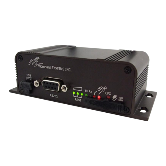
ANT3 Antenna (RP-SMA Female Antenna Connection) (Future) Status/Diagnostic LED’s for RSSI(x3), Tx, Rx, CELL, CPU Dual SIM (standard size) Card Slots CFG Button for factory default / firmware recovery operations Mounting Holes © Microhard Systems Inc. -
Page 20: Ipnxgii Mechanical Drawings
100.01 108.50 119.50 Drawing 3-1: IPnXGii Top View Dimensions 100.01 37.00 9.75 2.50 119.50 Drawing 3-2: IPnXGii Front View Dimensions 100.01 37.00 9.75 2.50 119.50 Drawing 3-3: IPnXGii Rear View Dimensions Note: All dimension units: Millimeter © Microhard Systems Inc. -
Page 21: Ipnxgii Connectors & Indicators
Ensure that the SIM card is installed properly by paying attention to the Table 3-2: RSSI LED’s diagram printed above the SIM card slot. The system will detect which slot is used. © Microhard Systems Inc. -
Page 22: Rear
Vin Pin Assignments Caution: Using a power supply that does not Ethernet RJ45 Connector Pin Number provide proper voltage may damage the modem. Source Voltage 9 - 30 Vdc Data Data Data Data Table 3-5: Ethernet PoE Connections © Microhard Systems Inc. -
Page 23: Configuration
IPnXGii as required. refer to Section 2.0: Quick Start for step by step instructions. In this section, all aspects of the Web Browser Interface, presented menus, and available configuration options will be discussed. © Microhard Systems Inc. -
Page 24: Logon Window
- particularly once the unit is deployed in the field - for one FORGET the new password primary reason: security. as it cannot be recovered. Image 4-0-3: Logon Window : Password Entry © Microhard Systems Inc. -
Page 25: System
The System Summary screen is displayed immediately after initial login, showing a summary and status of all the functions of the IPnXGii in a single display. This information includes System Status, Carrier Status, Cellular & LAN network information, version info, etc. Image 4-1-1: System Info Window © Microhard Systems Inc. -
Page 26: Settings
10s while the unit is powered up, the unit will reset and all settings will be reset to factory defaults. When disabled the unit will Enable reset, but the settings will not be overwritten. Disable © Microhard Systems Inc. -
Page 27: Date/Time
Time Over Network’ is selected, a NTP server can be defined. Over Network Date The calendar date may be entered in this field. Note that the (yyyy-mm-dd) Values entered value is lost should the IPnXGii lose power for some 2011.04.01 (varies) reason. © Microhard Systems Inc. -
Page 28: Ntp Server Settings
By default the modem only synchronizes the time and date during (seconds) Values system boot up (default: 0), but it can be modified to synchronize at a regular interval. This process does consume data and should be set accordingly. © Microhard Systems Inc. -
Page 29: Services
80 (http) and port 443 (HTTPS). HTTP/HTTPS Change as required, but keep in mind that if a non standard port is HTTP used, it must be specified in a internet browser to access the unit. HTTPS (example: http://192.168.168.1:8080). © Microhard Systems Inc. -
Page 30: Keepalive
Monitors the activity of Web UI. If the Web UI isn't accessed or Values (Selection) refreshed within the certain period which is specified by Console Timeout in System-Settings web page, the modem will send out the Enable / Disable connection request. © Microhard Systems Inc. - Page 31 The Keepalive Retry is the maximum number of connection failures Values (number) such as “Host unreachable” the unit will attempt before the unit will reboot itself to attempt to correct connection issues. The default number is 20, and valid value is from 10 to 200. © Microhard Systems Inc.
-
Page 32: Maintenance
4.0 Configuration 4.1.5 System > Maintenance Firmware Upgrade Occasional firmware updates may be released by Microhard Systems which may include fixes and/or new features. The firmware can be updated wirelessly using the WebUI. Image 4-1-7: Maintenance > Firmware Upgrade Erase Current Configuration... -
Page 33: Backup & Restore Configurations
Use the ‘Browse’ button to find the backup file that needs to be restored to the unit. Use the ‘Check Restore File’ button to verify that the file is valid, and then the option to restore the configuration is displayed, as seen above. © Microhard Systems Inc. -
Page 34: Reboot
The IPnXGii can be remotely rebooted using the System > Reboot menu. As seen below a button ‘OK, reboot now’ is provided. Once pressed, the unit immediately reboots and starts its boot up procedure. Image 4-1-9: System > Reboot © Microhard Systems Inc. -
Page 35: Network
4.2.1 Network > Summary The Network Summary display gives a overview of the currently configured network interfaces including the Connection Type (Static/DHCP), IP Address, Net Mask, Default Gateway, DNS, and IPv4 Routing Table. Image 4-2-1: Network > Network Status © Microhard Systems Inc. -
Page 36: Lan
If ‘DHCP’ is chosen this field will not appear and it will be populated automatically from the 192.168.168.1 DHCP server. Within any IP network, each device must have its own unique IP address. © Microhard Systems Inc. - Page 37 IP address information at the request of a DHCP Client, which receives the Mode information.) The option is used to enable or disable the DHCP service for devices Values (selection) connected to the LAN Port(s). On / Off © Microhard Systems Inc.
- Page 38 Specify the alternate DNS server address to be assigned to DHCP www.microhardcorp.com (for Values (IP Address) example) into the URL line of devices. a web browser, the website (IP Address) ‘could not be found’). © Microhard Systems Inc.
-
Page 39: Wan
If ‘Static’ Connection Type is selected, the Network Mask must be Values (IP Address) entered for the Network. If ‘DHCP’ is chosen this field will not appear and it will be populated automatically from the DHCP server. (no default) © Microhard Systems Inc. - Page 40 IP addresses. If set to auto and the Connection Type is set for DHCP the DHCP server will populate this field and the value set (no default) can be viewed on the Network > Status page. To add additional static servers, enter them here. © Microhard Systems Inc.
-
Page 41: Dhcp (Mac Binding)
IP Address if it requests a DHCP address. (no default) IP Address Enter the IP address to be assigned to the MAC address. Ensure this Values is a valid address on the current subnet. (no default) © Microhard Systems Inc. -
Page 42: Ddns
Enter a valid password for the user name of the DDNS service Values (characters) selected above. (none) Host This is the host or domain name for the IPnXGii as assigned by the Values (domain name) DDNS provider. (none) © Microhard Systems Inc. -
Page 43: Routes
Enter the network IP address for the destination. Values (IP Address) (192.168.168.0) Gateway Specify the Gateway used to reach the network specified above. Values (IP Address) 192.168.168.1 Netmask Enter the Netmask for the destination network. Values (IP Address) 255.255.255.0 © Microhard Systems Inc. -
Page 44: Ports (Switch)
IP address are shown, however not only DHCP assigned devices are listed in the device list, any devices, even those statically assigned, that are connected through the local network interface (RJ45) are displayed, including those connected through a hub or switch. Image 4-2-9: Network > Device List © Microhard Systems Inc. -
Page 45: Carrier
Not all statistics parameters displayed are applicable. The Received and Transmitted bytes and packets indicate the respective amount of data which has been moved through the radio. The Error counts reflect those having occurred on the wireless link. © Microhard Systems Inc. -
Page 46: Settings
The virtual IP address is configurable to allow access to the unit on the LAN/WAN connector once IP-Passthrough has been enabled. The firewall/rules must be configured to allow traffic, all incoming carrier traffic is blocked by default. © Microhard Systems Inc. -
Page 47: Dual Cards Management
IPNXGii will switch to the alternate SIM(Carrier). Keepalive This allows the IPnXGii to use the currently configured System > Values (Selection) Keepalive settings to determine how to check if the IPnXGii has lost connection to the current Carrier/SIM. Enable / Disable © Microhard Systems Inc. - Page 48 Auto APN (default) may allow the unit to quickly connect to a carrier, by cycling through a predetermined list of common APN’s. Auto APN will not work for private APN’s or for all carriers. Connect Mode (Verizon) IPn4Gii Verizon models initialized on the Version network will Values (characters) automatically configure the required settings needed to establish a connection with Verizon as a Wireless Carrier.
- Page 49 0, which means that there is no maximum and the modem will keep trying indefinitely. 0-100 Idle Time Out (3G) The maximum amount of time to pass before modem will timeout. The Values (seconds) default is 0 seconds. 0-65535 © Microhard Systems Inc.
- Page 50 Values (Selection) information to the end device. Enable / Disable SIM Card-2 Settings Settings for SIM Card-2 are identical to that of SIM Card-1, refer to the previous section for information on how to configure SIM Card-2. © Microhard Systems Inc.
-
Page 51: Sms
Image 4-3-3: SMS > SMS Command History Send SMS Message The SMS messages can be sent directly from the IPnXGii WebUI interface. Also, the SMS message history can be viewed. Image 4-3-4: SMS > SMS Send © Microhard Systems Inc. -
Page 52: Sms Config
MSC#MIOC3 close I/O ouput3 Set Phone Filter If enabled, the IPnXGii will only accept and execute commands Values (Selection) originating from the phone numbers in the Phone Filter List. Up to 6 numbers can be added. Enable / Disable © Microhard Systems Inc. - Page 53 (no default) Time Interval(s) SMS alerts, when active, will be sent out at the frequency defined Values (Seconds) here. RSSI Check Enable or disable the RSSI alerts. Values (Selection) Disable RSSI check Enable RSSI check © Microhard Systems Inc.
- Page 54 Changed to no-link I/O Status SMS Alerts can be sent based on the state changes of the Digital I/O Values (Selection) lines. Disable IO Check Enable: INPUT Changed Enable: Output Changed Enable: INPUT or OUTPUT Changed. © Microhard Systems Inc.
-
Page 55: Data Usage
Image 4-3-7: Carrier > Data Usage Status If enabled the IPnXGii will track the amount of cellular data consumed. If Values (selection) disabled, data is not recorded, even in the Current Data Usage display. Disable Enable © Microhard Systems Inc. - Page 56 If SMS is selected as the notification method, enter the phone number to Values (phone) send any SMS messages generated when the data usage exceeds the configured limits. +1403 Image 4-3-10: Data Usage > Email Config © Microhard Systems Inc.
- Page 57 Values (string) Email account used to send Emails. Most email servers require authentication on outgoing emails. Mail Recipient Enter the email address of the individual or distribution list to send the Values (xx@xx.xx) email notification to. host@ © Microhard Systems Inc.
-
Page 58: Firewall
The Firewall Summary allows a user to see detailed information about how the firewall is operating. The All, Filter, Nat, Raw, and Mangle options can be used to view different aspects of the firewall. Image 4-4-1: Firewall > Status © Microhard Systems Inc. -
Page 59: General
Access Rules, MAC List, IP List configurations. Access to ports 80 (HTTP) and 443 (HTTPS-if Block / Allow enabled), is still available unless disabled in the 4G Remote Management option. © Microhard Systems Inc. - Page 60 TCP packets that have invalid flag combinations. Reverse NAT The Reverse NAT allows access to the modem from the LAN port using the Values carrier’s IP address. Enable / Disable © Microhard Systems Inc.
-
Page 61: Port Forwarding
The default port for remote management is TCP DMZ Mode Enable or disable DMZ Mode. DMZ can be used to forward all traffic to the Values (selection) DMZ Server IP listed below. Disable / Enable © Microhard Systems Inc. - Page 62 Select the type of transport protocol used. For example Telnet uses TCP, Values (selection) SNMP uses UDP, etc. TCP / UDP / Both External Port Port number of the incoming request (from 4G/WAN-side). Values (Port #) 2000 © Microhard Systems Inc.
-
Page 63: Mac-Ip List
Each rule must have a unique name, up to 10 characters in length. MAC_List MAC Address Specify the MAC Address to be added to the list. Must be entered in the Values ( MAC Address correct format as seen above. Not case sensitive. 00:00:00:00:00:00 © Microhard Systems Inc. - Page 64 Match incoming traffic from the specified destination IP range. Boxes Values (IP Address) accept single IP Addresses without network masks, example: 192.168.1.0 to 192.168.1.255 represents all IP Addresses in the 192.168.1.0/24 192.168.0.0 network. (Put same IP in both boxes for a single IP match.) © Microhard Systems Inc.
-
Page 65: Rules
WAN/Carrier Access Control are configured in the previous menus. Source Select the zone which is to be the source of the data traffic. 3G/Cellular Values applies to the connection to the cellular carrier. The LAN/LAN1/USB refers to local connections on the IPnXGii. LAN/LAN1/WAN/Cell/USB/ None © Microhard Systems Inc. - Page 66 Match incoming traffic directed at the given destination port or port range. Values (port) (To specify a port range use a From:To (100:200) format) Protocol The protocol field defines the transport protocol type controlled by the rule. Values Both ICMP © Microhard Systems Inc.
-
Page 67: Firewall Default
4.4.6 Firewall > Firewall Default The Firewall Default option allows a user to return the modems firewall setting back to the default values without having to reset the entire modem. Image 4-4-7: Firewall > Firewall Default © Microhard Systems Inc. -
Page 68: Vpn
IPnXGii to create a tunnel to a network with VPN capabilities (Another IPnXGii or VPN capable device). The IPnXGii can also operate as a L2TP Server, allowing users to VPN into the unit from a remote PC, and a L2TP Client. Image 4-5-1: VPN > Summary © Microhard Systems Inc. -
Page 69: Gateway To Gateway
VPN device. Image 4-5-2: VPN > Gateway to Gateway Tunnel Name Enter a name for the VPN Tunnel. Up to 16 different tunnels can be Values (chars) created, each requiring a unique name. tunnel1 © Microhard Systems Inc. - Page 70 (no default) Group Subnet IP Define the local network by specifying the local subnet. The local and Values (IP Address) remote routers must use different subnets. (no default) © Microhard Systems Inc.
- Page 71 (no default) Subnet IP Address Define the remote network by specifying the local subnet. Values (IP Address) (no default) Subnet Mask Specify the subnet mask of the remote network address. Values (IP Address) 255.255.255.0 © Microhard Systems Inc.
- Page 72 Select value to match the values required by the remote VPN router. Values (selection) modp1024 modp1536 modp2048 Phase 2 Encryption Select value to match the Phase 1 Encryption type used by the remote Values (selection) VPN router. 3des aes128 aes256 © Microhard Systems Inc.
- Page 73 Dead Peer Detection is used to detect if there is a dead peer. Set the DPD Values (seconds) Delay (seconds), as required. DPD Timeout(s) Set the DPD (Dead Peer Detection) Timeout (seconds), as required. Values (seconds) DPD Action Set the DPD action, hold or clear, as required. Values (seconds) Hold Clear © Microhard Systems Inc.
-
Page 74: Client To Gateway (L2Tp Client)
Enter a name for the VPN Tunnel. Up to 16 different tunnels can be Values (chars) created, each requiring a unique name. tunnel1 Enable Used to enable (checked) is disable (unchecked) the VPN tunnel. Values (checkbox) Enable (Checked) © Microhard Systems Inc. - Page 75 The default is 0, which means the time is infinite. (0—65535) Username Enter the Username Values (chars) Preshared Key The preshared key is required to connect to the L2TP Server. Values (chars) IPSec Setup - See previous sections for additional info. © Microhard Systems Inc.
-
Page 76: Gre
Image 4-5-4: Network > Edit/Add GRE Tunnel Name Each GRE tunnel must have a unique name. Up to 10 GRE tunnels are Values (Chars(32)) supported by the IPnXGii. Enable Enable / Disable the GRE Tunnel. Values (selection) Disable / Enable © Microhard Systems Inc. - Page 77 This is the IP Address of the local tunnel. Values (IP Address) (varies) Netmask Enter the subnet mask of the local tunnel IP address. Values (IP Address) (varies) Subnet IP Address Enter the subnet address for the local network. Values (IP Address) (varies) © Microhard Systems Inc.
- Page 78 (varies) Subnet Mask The is the subnet mask for the remote network/subnet. Values (IP Address) (varies) IPsec Setup Refer to the IPsec setup in the VPN Site to Site section of the manual for more information. © Microhard Systems Inc.
-
Page 79: L2Tp Users
Values (characters) (no default) New Password Enter a password for the use. Values (characters) (no default) Confirm New Password IPnXGii Values (IP Address) Enter the password again, the will ensure that the password match. (no default) © Microhard Systems Inc. -
Page 80: Certificates
IPnXGii must use the required x.509 certificates in order to establish a secure tunnel between other devices. Certificate Management allows the user a place to manage these certificates. Image 4-5-7: VPN > Certificate Management © Microhard Systems Inc. -
Page 81: Multiwan
The Status menu gives an overview of both WAN connections and their configuration. WAN group 1 is the wired WAN and WAN group 2 is the Cellular connection to a wireless carrier. Image 4-6-1: MultiWAN > Status © Microhard Systems Inc. -
Page 82: Settings
Normally this is the wired WAN connection to an ISP. Carrier Load Balancer Fast Balancer Health Monitor Interval This is the frequency at which the modem will send ICMP packets to the Values (selection) defined host to determine if the interface has failed. 5,10,20,30,60,120(sec.) Disable © Microhard Systems Inc. - Page 83 This defines the number of successful attempts required before recovering the failed interface. 1, 3, 5, 10, 15, 20 Failover Traffic Destination Select the interface to use once failover has occurred. Values (selection) Carrier or WAN Disable Load Balancer Compatibility Fast Balancer Compatibility © Microhard Systems Inc.
-
Page 84: Serial
The Status window gives a summary of the serial ports on the IPnXGii. The Status window shows if the com port has been enabled, how it is configured (Connect As), and the connection status. Image 4-7-1: Serial > Summary © Microhard Systems Inc. -
Page 85: Rs232/Console/Rs485 Settings
(TCP and UDP only) RS485 - The RS485 port is used as a data port for RS485 devices. In the IPnXGii it is a fully independent serial data port with full support. Image 4-7-2: Comport > Settings Configuration © Microhard Systems Inc. -
Page 86: Data Baud Rate
‘None’. When CTS Framing is selected, the IPnXGii uses the CTS signal to gate the output data on the serial port. Software flow control (XON/XOFF) is not supported. Values (selection) None Hardware CTS Framing Drawing 4A: CTS Output Data Framing © Microhard Systems Inc. - Page 87 When enabled the data will continue to buffer received on the Values (selection) serial data port when the radio loses synchronization. When Disable / Enable disabled the IPnXGii will disregard any data received on the serial data port when radio synchronization is lost. © Microhard Systems Inc.
- Page 88 MODBUS TCP Status This option will enable or disable the MODBUS decoding and Values (selection) encoding features. Disable / Enable MODBUS TCP Protection Key MODBUS encryption key used for the MODBUS TCP Values (string) Protection Status feature. 1234 © Microhard Systems Inc.
-
Page 89: Ip Protocol Config
Requires more bandwidth Default: 20001 than UDP. Incoming Connection Timeout Established when the TCP Server will terminate the TCP connection is the connection is in an idle state. Default: 300 (seconds) © Microhard Systems Inc. -
Page 90: Tcp Client/Server
TTL: Time to Live is the number of hops a packet can travel before being discarded. In the context of multicast, a TTL value of 1 restricts the range of the packet to the same subnet. © Microhard Systems Inc. -
Page 91: Udp Point-To-Multipoint (Mp)
A valid multicast address the unit is to listen to receive multicast UDP packets sent by another UDP Multipoint-to-Multipoint unit. Default: 224.1.1.1 Listening Multicast Port UDP port that the unit will listen to for multicast UDP packets sent by another UDP Multipoint-to-Multipoint unit. Default: 20011 © Microhard Systems Inc. -
Page 92: Smtp Client
Generally this doe not need to be changed. Default: CLIENT Response String This is the handshaking string that will be sent by the modem once the expected string is received. Generally this does not need to be changed. Default: CLIENTSERVER © Microhard Systems Inc. -
Page 93: Gps Transparent Mode
When there is data coming, new ppp connection will be created. Default: 30 GPS Transparent Mode: When in GPS Transparent Mode, GPS data is reported out the serial port at 1 second intervals. Sample output is shown below: Image 4-7-4: RS232 > GPS Transparent Mode © Microhard Systems Inc. -
Page 94: Usb
USB port. To use the Serial or NDIS function of the IPnXGii, you must first attaint and install the USB drivers. Windows Drivers are available from the Support Desk on the Microhard Systems Inc website. Please register and login into: http://www.microhardcorp.com/support... -
Page 95: Serial
Disabled (console mode) via the USB-to-Serial connection to it, the escape sequence of '+++' may be entered at the Data Baud Rate for which the port is configured. For more information about any of the Data Port field parameters refer to RS232 Configuration. Image 4-8-2: USB Configuration Data Port © Microhard Systems Inc. -
Page 96: Ndis
This will be the Subnet Mask automatically assigned to the device (PC) Values connected to the USB port of the IPnXGii 255.255.255.0 Host IP This will be the IP Address automatically assigned to the device (PC) Values connected to the USB port of the IPnXGii 192.168.111.2 © Microhard Systems Inc. -
Page 97: I/O
See Table 4-8-1 for I/O specifications. Status The Status section will display the current state and measured voltage (Meter) of any I/O’s configured as inputs. The WebUI will also display the current state of each control output. © Microhard Systems Inc. - Page 98 Pin includes an internal 56KΩ resistor pull up to 3.3 VDC. —- I/O 1 - 8 Open drain drive to (Output) ground —- Maximum open circuit voltage applied Typical application is to drive a relay coil to ground. Table 4-9-1: Digital I/O Specifications © Microhard Systems Inc.
-
Page 99: Gps
If the unit had a GPS signal (GPS Module enabled and antenna attached), it will report the specific GPS coordinates of the modem, otherwise only the estimated coordinates reported by the Carrier. © Microhard Systems Inc. - Page 100 GPS features of the IPnXGii a cellular antenna must be connected to the GPS Antenna Port. Standalone GPS TCP Port Specify the TCP port on the IPnXGii where the GPS service is running and Values remote systems can connect and poll for GPSD data. 2947 © Microhard Systems Inc.
-
Page 101: Report
Enable UDP and/or Email or disable GPS Reporting. Up to 4 reports can Values (selection) be set up and configured independently. Disable UDP Report Email Report Time Interval The interval timer specifies the frequency at which the GPS data is Values (seconds) reported in seconds. © Microhard Systems Inc. - Page 102 Enter the login credentials here. Username / password Mail Recipient Some outgoing mail servers require a username and password to prevent Values (characters) an account being used for spam. Enter the login credentials here. host@email.com © Microhard Systems Inc.
-
Page 103: Gpsgate
SMS Only TCP Alive Mode / Alive Time Interval TCP alive mode will keep TCP connection alive if tracker is not enabled or Values (seconds) the tracker interval is too long. The default is 150 seconds. © Microhard Systems Inc. - Page 104 Specify what happens when the GPS data is invalid, either use the last Values (selection) valid position or do not use the last valid position. Not Use Last Valid Position Use Last Valid Position GpsGate - TCP Mode Image 4-10-5: GPS > GpsGate TCP Mode © Microhard Systems Inc.
- Page 105 When GPS Invalid, Sending Data Specify what happens when the GPS data is invalid, either use the last Values (selection) valid position or do not use the last valid position. Not Use Last Valid Position Use Last Valid Position © Microhard Systems Inc.
-
Page 106: 5Recorder
DI/DO Changed The IPnXGii can detect and report the current GPS info when a digital input Values (selection) or output status changes, regardless of the time interval setting. Record / Don’t Record © Microhard Systems Inc. - Page 107 Select Record to record the current 3G/Cellular RSSI level when a GPS Values (selection) entry is recorded. (-dB). Record / Don’t Record Altitude Select Record to record the current Altitude when a GPS entry is recorded Values (selection) (meters). Record / Don’t Record © Microhard Systems Inc.
-
Page 108: Load Record
(internet access required), by selecting “Trace Map”, or “Quick Trace”. The screenshots below show the raw data that can be viewed and the Trace Map/Quick Trace output. Image 4-10-7: GPS > GPS Load Record © Microhard Systems Inc. - Page 109 Enter the address or IP address of the remote server to which the data is to Values (IP) be sent. nms.microhardcorp.com Server Port Enter the UDP/TCP port number of the remote server to which the data is Values (Port) to be sent. 30175 © Microhard Systems Inc.
-
Page 110: Taip
UDP, this will define how the connection (TCP) or data is sent (UDP) to the server. UDP / TCP Remote TAIP Port Enter the TCP or UDP port number used on the Remote TAIP server. Values (TCP/UDP) UDP / TCP © Microhard Systems Inc. - Page 111 Set the frequency at which TAIP messages are reported to the remote Values (seconds) server. The unit used is seconds, and the default value is 60 seconds. Vehicle ID Set the Vehicle ID using 4 alpha-numeric characters. Values (chars) 0000 © Microhard Systems Inc.
-
Page 112: Applications
Image 4-11-1: Applications > Modbus Status Disable or enable the Modbus service on the IPnXGii. Values (selection) Disable Service Enable Service TCP Mode Status Disable or enable the Modbus TCP Connection Service on the IPnXGii. Values (selection) Disable Enable © Microhard Systems Inc. - Page 113 Master IP Filter Set It is possible to only accept connections from specific Modbus Master IP’s, Values (selection) to use this feature enable the Master IP Filter and specify the IP Addresses in the fields provided. Disable / Enable © Microhard Systems Inc.
-
Page 114: Serial (Com) Modbus
2400 230400 28800 7200 1200 115200 19200 4800 Data Format This setting determines the format of the data on the serial port. Values (selection) The default is 8 data bits, No parity, and 1 Stop bit. © Microhard Systems Inc. -
Page 115: Modbus Data Map
4.0 Configuration 4.10.1.3 Modbus > Modbus Data Map Image 4-11-3: Applications > Modbus Data Map © Microhard Systems Inc. -
Page 116: Netflow Report
The default of 0.0.0.0 will collect and report information about all addresses connected to the interface selected below. 0.0.0.0 Interface Select between LAN, WAN and Carrier interfaces, or capture data from all Values (selection) interfaces. LAN / WAN / Carrier / ALL © Microhard Systems Inc. - Page 117 Filter expression selects which packets will be captured. If no expression is Values (chars) given, all packets will be captured. Otherwise, only packets for which expression is `true' will be captured. Example: tcp&&port 80 (no default) The “tcpdump” manual, available on the internet provides detailed expression syntax. © Microhard Systems Inc.
-
Page 118: Local Monitor
At this time the IPnXGii will restart the DHCP service. (5- 65535 seconds) Waiting DHCP Timeout This field defines the amount of time the IPnXGii will wait to detect the Values (seconds) monitored device before it will reboot the modem. (30-65535 seconds) © Microhard Systems Inc. -
Page 119: Event Report
If Management is selected, additional check boxes appear below to select SDP_Event the interfaces to report to the Microhard NMS system. Management Remote IP Enter the IP Address of a reachable host to send the UDP packets Values (IP Address) 0.0.0.0 © Microhard Systems Inc. -
Page 120: Message Structure
2 bits 00 no 01 yes (0x4) WAN Info - 2 bits 00 no 01 yes (0x10) sdp_event message structure spd_cmd (1 byte(0x01)) content length (1 byte) spd_package - same as spd response inquiry package format © Microhard Systems Inc. - Page 121 --- 2 BYTES(UINT16_T) product name --- STRING(1—64 bytes) image name --- STRING(1—64 bytes) domain name --- STRING(1—64 bytes) domain password --- STRING(32 bytes) // MD5 encryption module list --- 5 BYTES // radio, ethernet, carrier, usb, com © Microhard Systems Inc.
-
Page 122: Websocket
Enable or disable the web socket service in the modem. Values (selection) Enable / Disable Web Socket Port Enter the desired web socket TCP port number. The default is 7681, and Values (TCP port) the valid range is 100 to 65535. 7681 © Microhard Systems Inc. - Page 123 If enabled the modem will report carrier information to the websocket. Values (selection) Disable / Enable Comport Data If enabled, and the RS232 port is configured for TCP Server, the comport Values (selection) data will be reported to the web socket. Disable / Enable © Microhard Systems Inc.
-
Page 124: Diagnostics
Network Tools Trace Route The Trace Route command can be used to provide connectivity data by providing information about the number of hops, routers and the path taken to reach a particular destination. Image 4-11-9: Diagnostics > Trace Route © Microhard Systems Inc. -
Page 125: Admin
The default password for ‘admin’ is ‘admin’. admin Confirm Password The exact password must be entered to confirm the password change, Values (characters) if there is a mistake all changes will be discarded. admin © Microhard Systems Inc. - Page 126 Min 5 characters Max 32 characters Password / Confirm Password Passwords must be a minimum of 5 characters. The Password must Values (characters) be re-entered exactly in the Confirm Password box as well. (no default) min 5 characters © Microhard Systems Inc.
-
Page 127: Authentication (Radius)
Valid RADIUS server IP address 0.0.0.0 RADIUS Secret If the Authorization Mode has been set to RADIUS&Local, obtain the Values RADIUS Secret for his particular client from your RADIUS Server Administrator and enter it into this field. nosecret © Microhard Systems Inc. -
Page 128: Nms
The Microhard NMS is a no cost server based monitoring and management service offered by Microhard Systems Inc. Using NMS you can monitor online/offline units, retrieve usage data, perform backups and centralized upgrades, etc. The following section describes how to get started with NMS and how to configure the IPnXGii to report to NMS. - Page 129 Once confirmed, this account will be the administrator of the domain. The administrator can manage sub- domain and user accounts that belong to this domain. Once NMS has been configured, each IPnXGii must be configured to report into NMS. Image 4-12-5: NMS Settings © Microhard Systems Inc.
- Page 130 The Interval defines how often data is reported to NMS. The more often Values (seconds) data is reported, the more data is used, so this should be set according to a user’s data plan. (0 to 65535 seconds) © Microhard Systems Inc.
- Page 131 The Interval defines how often the IPnXGii checks with the NMS System to Values (min) determine if there are any tasks to be completed. Carrier data will be consumed every time the device probes the NMS system. © Microhard Systems Inc.
-
Page 132: Snmp
The pages that follow describe the different fields required to set up SNMP on the IPnXGii. MIBS may be requested from Microhard Systems Inc. The MIB file can be downloaded directly from the unit using the ‘Get MIB File’ button on the Network >... - Page 133 SNMP queries. Being part of the community allows the SNMP agent to process SNMPv1 and SNMPv2c requests. This community name has private only READ/WRITE priority. SNMP V3 User Name Defines the user name for SNMPv3. Values (string) V3user © Microhard Systems Inc.
- Page 134 The community name which may receive traps. Values (string) TrapUser Trap Manage Host IP Defines a host IP address where traps will be sent to (e.g. SNMP Values (IP Address) management system PC IP address). 0.0.0.0 © Microhard Systems Inc.
-
Page 135: Discovery
Discovery Service Status Use this option to disable or enable the discovery service. Values (selection) Disable / Discoverable / Changable Server Port Settings Specify the port running the discovery service on the IPnXGii unit. Values (Port #) 20077 © Microhard Systems Inc. -
Page 136: Power Saving Modes
Sniff Mode - The Bullet will enter power saving mode after the Idle time has expired until the sleep timer expires, unless woken up by data being detected on the Ethernet and/or Serial com port. © Microhard Systems Inc. -
Page 137: Logout
4.0 Configuration 4.12.7 System > Logout The logout function allows a user to end the current configuration session and prompt for a login screen. Image 4-12-9: System > logout © Microhard Systems Inc. -
Page 138: At Command Line Interface
Once communication is established, a login is required to access the AT Command interface, once logged in, the AT Command Line Interface menu is displayed. Type “?” or Help to list the menu commands. Default Settings: IPnXGii login: admin Password: admin Image 5-2: AT Command Window © Microhard Systems Inc. -
Page 139: Telnet
Once verified, the AT Command Line Interface menu is shown and AT Commands can now be issued. (Type “?” or Help to list the commands). The factory default network settings: IP: 192.168.168.1 Subnet: 255.255.255.0 Gateway: 192.168.168.1 Image 5-4: Telnet AT Command Session © Microhard Systems Inc. -
Page 140: At Command Syntax
Once AT commands are entered, they must be saved into the file system to enable the changes. AT&W Saves changes. ATO or ATA Exits the AT Command Line Interface, if used before AT&W, changes are discarded. © Microhard Systems Inc. -
Page 141: Supported At Commands
ATE0 <enter> Example Input: ATE0 <enter> Response: ATE1 Description Command Syntax Enables Local Echo. ATE1 <enter> Example Input: ATE1 <enter> Response: AT+TEST Description Command Syntax Echo TEST AT+TEST <enter> Example Input: AT+TEST <enter> Response: AT ECHO TEST: © Microhard Systems Inc. - Page 142 Description Command Syntax Read modem profile to editable profile. (Reserved) AT&R <enter> Example Input: AT&R <enter> Response: AT&V Description Command Syntax Read modem active profile. AT&V <enter> Example Input: AT&V <enter> Response: &V: hostname:Bullet timezone:MST7MDT,M3.2.0,M11.1.0 systemmode:gateway © Microhard Systems Inc.
- Page 143 Command Syntax Reboots the modem. AT+MREB <enter> Example Input: AT+MREB <enter> Response: OK. Rebooting... Description Command Syntax Quit. Exits AT Command session and returns you to ATA <enter> login prompt. Example Input: ATA <enter> Response: Bullet Login: © Microhard Systems Inc.
- Page 144 ATA <enter> Response: Bullet Login: AT+CMGS Description Command Syntax Send SMS message. To send message CTRL+Z AT+CMGS=<Phone Number><CR> must be entered, to exit, ESC. text is entered <CTRL+Z/ESC> Example Input: AT+CMGS=4035553776 <enter> 4035553776 Test <ctrl+z> Response: © Microhard Systems Inc.
- Page 145 1 - Lists all read messages 4 - Lists all messages Example Input: AT+CMGL=1 <enter> Response: AT+CMGL=1 +CMGL: 0,"REC READ","+14035553776",,"2013/10/04,11:12:27-06" Test Message 1 +CMGL: 1,"REC READ","+14035553776",,"2013/10/04,11:12:53-06" Test Message 2 +CMGL: 2,"REC READ","+14035553776",,"2013/10/04,11:13:06-06" Another test message! © Microhard Systems Inc.
- Page 146 Command Syntax Modem Record Information AT+GMR <enter> Example Input: AT+GMR <enter> Response: +GMR: Hardware Version:v1.0.0 Software Version:v1.1.0 build 1060 Copyright: 2012 Microhard Systems Inc. System Time: Mon Dec 2 16:03:51 2013 AT+GMI Description Command Syntax Get Manufacturer Identification AT+GMI=<enter> Example Input: AT+GMI<enter>...
- Page 147 AT+CIMI Description Command Syntax Check modem’s IMEI and IMSI numbers. AT+CIMI <enter> Example Input: AT+CIMI <enter> Response: +CIMI: IMEI:012773002108403, IMSI:302720406982933 AT+CCID Description Command Syntax Check modem’s SIM card number. AT+CCID=<enter> Example Input: AT+CCID<enter> Response: +CCID: 89302720401025355531 © Microhard Systems Inc.
- Page 148 Wan IP:0.0.0.0 Wan MASK:0.0.0.0 System: Device:Bullet Product:Bullet Image:Bullet Hardware:Rev A Software:v1.2.0 build 1007 Copyright: 2013-2014 Microhard Systems Inc. Time: Thu Jul 10 09:48:28 2014 AT+MMNAME Description Command Syntax Modem Name / Radio Description. 30 chars. AT+MMNAME=<modem_name> Example Input: (To set value) AT+MMNAME=Bullet_CLGY<enter>...
- Page 149 1 Enable Example Input: AT+MDHCP=1 <enter> Response: AT+MDHCPA Description Command Syntax Define the Starting and Ending IP Address (range) AT+MDHCPA=<Start IP>, <End IP> assignable by DHCP on the local Ethernet interface. Example Input: AT+MDHCPA=192.168.168.100,192.168.168.200 <enter> Response: © Microhard Systems Inc.
- Page 150 Set LAN static IP AT+MSIP=<static IP address> <enter> Example Input: AT+MSIP=192.168.168.1 <enter> Response: +MSIP: setting and restarting network... AT+MSCT Description Command Syntax Set LAN Connection Type. AT+MSCT=<Mode> Mode: DHCP Static IP Example Input: AT+MSCT=1 <enter> Response: © Microhard Systems Inc.
- Page 151 AT+MCNTO Description Command Syntax Sets the timeout value for the serial and telnet AT+MCNTO=<Timeout_s> consoles. Once expired, user will be return to login 0 - Disabled prompt. 0 - 65535 (seconds) Example Input: AT+MCNTO=300 <enter> Response: © Microhard Systems Inc.
- Page 152 AT+MRTF=1 <enter> Response: AT+MSCMD Description Command Syntax Enable/Disable SMS Commands and if configured AT+MSCMD=<Mode>[,<Filter Mode>[,<Phone the phone filter list. No.1>[,...,<Phone No.6>]]] Mode: Disable Example Enable SMS Command Filter Mode: Input: Disable AT+MSCMD=1,1,403556767,4057890909<enter> Enable Phone Filter Response: © Microhard Systems Inc.
- Page 153 Used to set or change the ADMIN password for the AT+MPWD=<New password>,<confirm Bullet. password> password: at least 5 characters Example Input: AT+MPWD=admin,admin<enter> Response: AT+MIKACE Description Command Syntax Enable or Disable IMCP ICMP keep-alive check. AT+MIKACE=<Mode> Mode: Disable Enable Example Input: AT+MIKACE=1<enter> Response: © Microhard Systems Inc.
- Page 154 Select DDNS service provider, and login credentials AT+MDDNS=<service type>,<host>,<user as required for DDNS services. name>,<password> service type: 0 changeip 1 dyndns 2 eurodyndns 3 hn 4 noip 5 ods 6 ovh 7 regfish 8 tzo 9 zoneedit Example Input: AT+MDDNS=0,user.dydns.org,user,password <enter> Response: © Microhard Systems Inc.
- Page 155 Time_s>] Mode: Disable Example Enable NMS Report Input: AT+MNMSR=1,20200,300<enter> Response: AT+MGPSR1 AT+MGPSR2 AT+MGPSR3 AT+MGPSR4 Description Command Syntax Define GPS Report No.1/2/3/4. AT+MGPSR1=<Mode>[,<Remote IP>,<Remote Port>,<Interval Ti me_s>] Mode: Example Disable Enable UDP Report Input: AT+MGPSR1=1,192.168.168.25,20175,600 <enter> Response: © Microhard Systems Inc.
- Page 156 AT+MCTPS1=<Mode> Mode: Disable Enable Example Input: AT+MCTPS1=0<enter> Response: AT+MCTBR1 Description Command Syntax Set Comport baud rate. AT+MCTBR1=<Baud Rate> Baud Rate: 1200 2400 3600 Example 4800 7200 Input: 9600 AT+MCTBR1=13<enter> 14400 Response: 19200 28800 38400 57600 115200 © Microhard Systems Inc.
- Page 157 Data Format: Example Input: AT+MCTDF1=0<enter> Response: AT+MCTDM1 Description Command Syntax Set Comport data mode. AT+MCTDM1=<Data Mode> Data Mode: Seamless Transparent Example Input: AT+MCTDM1=1<enter> Response: AT+MCTCT1 Description Command Syntax Set Comport character timeout. AT+MCTCT1=<timeout_s> Example Input: AT+MCTCT1=0<enter> Response: © Microhard Systems Inc.
- Page 158 Response: AT+MCTP1 Description Command Syntax Set Comport port priority. AT+MCTP1=<Mode> Mode: Normal Medium High Example Input: AT+MCTP1=0<enter> Response: AT+MCTNCDI1 Description Command Syntax Enable/Disable Comport port no-connection data AT+MCTNCDI1=<Mode> intake. Mode: Disable Enable Example Input: AT+MCTNCDI1=1<enter> Response: © Microhard Systems Inc.
- Page 159 SMS Transparent Mode GPS Transparent Mode AT+MCTTC1 Description Command Syntax Set Comport TCP Client parameters when IP AT+MCTTC1=<Remote Server IP>, <Remote Protocol Mode is set to TCP Client. Server Port>, <Outgoing timeout_s> Example Input: AT+MCTTC1=0.0.0.0,20002,60<enter> Response: © Microhard Systems Inc.
- Page 160 Multi-polling AT+MCTCS1=0.0.0.0,20002,60,0,100,20002,300<en ter> Response: AT+MCTUPP1 Description Command Syntax Set UDP Point-to-Point parameters when IP AT+MCTUPP1=<Remote Server IP>, <Remote Protocol is set to UDP Point-to-Point mode. Server Port>, <Liste ner Port>, <UDP timeout_s> Example Input: AT+MCTUPP1=0.0.0.0,20002,20002,10<enter> Response: © Microhard Systems Inc.
- Page 161 AT+MCTUPMM1=0.0.0.0,20012,224.1.1.2,20002<enter> Response: AT+MCTUMPMP1 Description Command Syntax Set UDP Multipoint-to-Multipoint parameters when AT+MCTUMPMP1=<Multicast IP>, <Multicast IP Protocol is set to UDP Multipoint-to-Multipoint Port>, <Time to live>, <Listen Multicast IP>, mode. <Listen Multicast Port> Example Input: AT+MCTUMPMP1=224.1.1.2,20012,1,224.1.1.2,20012<enter> Response: © Microhard Systems Inc.
- Page 162 AT+MCTPS2=<Mode> Mode: Disable Enable Example Input: AT+MCTPS2=0<enter> Response: AT+MCTBR2 Description Command Syntax Set Comport baud rate. AT+MCTBR2=<Baud Rate> Baud Rate: 1200 2400 3600 Example 4800 7200 Input: 9600 AT+MCTBR2=13<enter> 14400 Response: 19200 28800 38400 57600 115200 © Microhard Systems Inc.
- Page 163 Data Format: Example Input: AT+MCTDF2=0<enter> Response: AT+MCTDM2 Description Command Syntax Set Comport data mode. AT+MCTDM2=<Data Mode> Data Mode: Seamless Transparent Example Input: AT+MCTDM2=1<enter> Response: AT+MCTCT2 Description Command Syntax Set Comport character timeout. AT+MCTCT2=<timeout_s> Example Input: AT+MCTCT2=0<enter> Response: © Microhard Systems Inc.
- Page 164 Response: AT+MCTP2 Description Command Syntax Set Comport port priority. AT+MCTP2=<Mode> Mode: Normal Medium High Example Input: AT+MCTP2=0<enter> Response: AT+MCTNCDI2 Description Command Syntax Enable/Disable Comport port no-connection data AT+MCTNCDI2=<Mode> intake. Mode: Disable Enable Example Input: AT+MCTNCDI2=1<enter> Response: © Microhard Systems Inc.
- Page 165 SMS Transparent Mode GPS Transparent Mode AT+MCTTC2 Description Command Syntax Set Comport TCP Client parameters when IP AT+MCTTC2=<Remote Server IP>, <Remote Protocol Mode is set to TCP Client. Server Port>, <Outgoing timeout_s> Example Input: AT+MCTTC2=0.0.0.0,20002,60<enter> Response: © Microhard Systems Inc.
- Page 166 Multi-polling AT+MCTCS2=0.0.0.0,20002,60,0,100,20002,300<en ter> Response: AT+MCTUPP2 Description Command Syntax Set UDP Point-to-Point parameters when IP AT+MCTUPP2=<Remote Server IP>, <Remote Protocol is set to UDP Point-to-Point mode. Server Port>, <Liste ner Port>, <UDP timeout_s> Example Input: AT+MCTUPP2=0.0.0.0,20002,20002,10<enter> Response: © Microhard Systems Inc.
- Page 167 AT+MCTUPMM2=0.0.0.0,20012,224.1.1.2,20002<enter> Response: AT+MCTUMPMP2 Description Command Syntax Set UDP Multipoint-to-Multipoint parameters when AT+MCTUMPMP2=<Multicast IP>, <Multicast IP Protocol is set to UDP Multipoint-to-Multipoint Port>, <Time to live>, <Listen Multicast IP>, mode. <Listen Multicast Port> Example Input: AT+MCTUMPMP2=224.1.1.2,20012,1,224.1.1.2,20012<enter> Response: © Microhard Systems Inc.
- Page 168 Get/Set output control AT+MIOOC=<Index>,<Output Control> Index: The index of IO port, 1 to 2 Output Control: Example 0 Open 1 Close Input: AT+MIOOC=1,1 <enter> Response: Input: AT+MIOOC? Response: +MIOOC: IO Output Control OutputCtrl1: 1 Close OutputCtrl2: 0 Open © Microhard Systems Inc.
- Page 169 AT+MIOMETER Description Command Syntax Get IO meter (V) AT+MIOMETER <enter> Example Input: AT+MIOMETER <enter> Response: +MIOMETER: IO meter(V) iovolts1=12.25 iovolts2=2.74 AT+IMEI Description Command Syntax Get Modem’s IMEI AT+IMEI <enter> Example Input: AT+IMEI <enter> Response: +IMEI: 352237050103870 © Microhard Systems Inc.
- Page 170 AT+IMSI <enter> Response: +IMSI: 302610012606734 AT+IMSI Description Command Syntax Get Modem’s IMSI AT+IMSI <enter> Example Input: AT+IMSI <enter> Response: +IMSI: 302610012606734 AT+NETRSSI Description Command Syntax Get Modem’s RSSI AT+NETRSSI <enter> Example Input: AT+NETRSSI <enter> Response: +NETRSSI:-65 © Microhard Systems Inc.
- Page 171 +POWERIN: 11.77 AT+BOARDTEMP Description Command Syntax Get Modem’s Board Temperature (C) AT+BOARDTEMP <enter> Example Input: AT+BOARDTEMP <enter> Response: +BOARDTEMP: 44.79 AT+WANIP Description Command Syntax Get Modem’s WAN IP AT+WANIP <enter> Example Input: AT+WANIP <enter> Response: +WANIP: 74.186.198.97 © Microhard Systems Inc.
-
Page 172: Command Syntax
Define Event UDP Report No.2 AT+MEURD3 Define Event UDP Report No.3 AT+MNMSR Define NMS Report AT+MGPSR1 Define GPS Report No.1 AT+MGPSR2 Define GPS Report No.2 AT+MGPSR3 Define GPS Report No.3 AT+MGPSR4 Define GPS Report No. (Continued….) © Microhard Systems Inc. - Page 173 Get/Set output control AT+MIOSTATUS Get IO status AT+MIOMETER Get IO meter(V) AT+IMEI Get Modem's IMEI AT+IMSI Get Modem's IMSI AT+NETRSSI Get Modem's RSSI AT+POWERIN Get Modem's Voltage AT+BOARDTEMP Get Modem's Temperature AT+WANIP Get Modem's WAN IP © Microhard Systems Inc.
-
Page 174: Appendices
(DCE); the module transmits data on the RX line, and receives on TX. “DCE” and “module” are often synonymous since a module is typically a DCE device. “DTE” is, in most applications, a device such as a host PC. © Microhard Systems Inc. -
Page 175: Appendix B: Ip-Passthrough Example
For this example we are going to change it to port 8080. When changing port numbers on the IPn3Gii, it is recommended to reboot the unit before continuing, remember the new WebUI port is now 8080 when you log back into the IPn3Gii. (e.g. 192.168.168.1:8080). © Microhard Systems Inc. - Page 176 WAN IP Address of the IPn3Gii into a web browser. As seen below, when the IP Address of the IPn3Gii is entered, the data is passed through to the attached PC. The screen shot below shows that our test setup was successful. © Microhard Systems Inc.
-
Page 177: Appendix C: Port Forwarding Example
IPn3Gii. See the Firewall Example in the next Appendix for information on how to allow connections from an IP or to open ports. Once that is complete, remember to “Submit” the changes. © Microhard Systems Inc. - Page 178 IP-Passthrough example, so the result should be as follows: To access the other devices/services: For the PLC Web Server: 74.198.186.193:8081, for the Camera 74.198.186.193:8082, and for the Modbus on the PLC telnet to 74.198.186.193:10502 etc. © Microhard Systems Inc.
-
Page 179: Appendix D: Vpn (Site To Site) Example
Rules or IP lists have been setup to allow specific traffic to pass through the IPnXGii. Once that is complete, remember to “Apply” the changes. Step 2 Configure the LAN IP and subnet for each IPnXGii. The subnets must be different and cannot overlap. Site A Site B © Microhard Systems Inc. - Page 180 Must Match! Step 4 Submit changes to both units. It should be possible to ping and reach devices on either end of the VPN tunnel if both devices have been configured correctly and have network connectivity. © Microhard Systems Inc.
-
Page 181: Appendix E: Firewall Rules Example
Log into the IPn3Gii (Refer to Quick Start). Navigate to the Firewall > General tab as shown below and block all Carrier traffic by setting the Carrier Request to Block, and disable Carrier Remote Management. Be sure to Apply the settings. At this point it should be impossible to access the IPn3Gii from the Cellular Connection. © Microhard Systems Inc. - Page 182 IPn3Gii to a specific IP would have been to use the MAC-IP List Tool. By using Rules, we can not only limit specific IP’s, but we can also specify ports that can be used by an allowed IP address. © Microhard Systems Inc.
-
Page 183: Appendix F: Troubleshooting
Question: I connected a device to the serial port of the IPnXGii and nothing happens? Answer: In addition to the basic serial port settings, the IP Protocol Config has to be configured. Refer to the COM0/1 Configuration pages for a description of the different options. © Microhard Systems Inc. - Page 184 Answer: When using IP-Passthrough, the Carrier IP is assigned to the device connected to the Ethernet port, all traffic is passed through to that device. In order for IP-Passthrough to work, the connected local device must have DHCP enabled. © Microhard Systems Inc.
- Page 185 3. Local Device Monitor - The IPnXGii will monitor a local device, if that device is not present the IPnXGii may reboot. Network > LocalMonitor. _______________________________________________________________ Question: How do I set up VPN? Answer: Refer to the VPN Appendix for an example. © Microhard Systems Inc.
- Page 186 150 Country Hills Landing NW Calgary, Alberta Canada T3K 5P3 Phone: (403) 248-0028 Fax: (403) 248-2762 www.microhardcorp.com © Microhard Systems Inc.
Need help?
Do you have a question about the IPn4Gii and is the answer not in the manual?
Questions and answers