Table of Contents
Advertisement
Advertisement
Table of Contents

Related Manuals for Microhard Systems IPn3G


Summary of Contents for Microhard Systems IPn3G
- Page 1 Operating Manual IPn3G / IPn3Gb 3G/HSPA/HSPA+ Cellular Ethernet/Serial/USB Gateway Revision 3.1 - March 2014 Firmware: v2.2.0-r2102 150 Country Hills Landing N.W. Calgary, AB, Canada T3K 5P3 Phone: (403) 248-0028 Fax: (403) 248-2762 www.microhardcorp.com...
- Page 2 Warranty Microhard Systems Inc. warrants that each product will be free of defects in material and workmanship for a period of one (1) year for its products. The warranty commences on the date the product is shipped by Microhard Systems Inc. Microhard Systems Inc.’s sole liability and responsibility under this warranty is to repair or replace any product which is returned to it by the Buyer...
- Page 3 Highlights a key feature, point, or step which is noteworthy. Keeping these in mind will simplify or enhance device usage. An idea or suggestion to improve efficiency or enhance usefulness. Information Information regarding a particular technology or concept. © Microhard Systems Inc.
- Page 4 Ce dispositif a été approuvé de façon modulaire. Le fabricant, le nom du produit, et la FCC et de l'Industrie du Canada identifiants de ce WARNING produit doit figurer sur l'étiquette à l'extérieur de l'équipement de l'utilisateur final. SAMPLE LABEL REQUIREMENT / EXIGENCE D'ÉTIQUETTE : IPn3G Version 2 IPn3G Version 1 FCCID: RI7T56KL1 FCCID: IHDT56KL1...
-
Page 5: Revision History
Commands, misc corrections & formatting. Changes current up to firmware v2.0.44-r2090. Added FCC ID for IPn3Gb, Added additional spec data for IPn3Gb Jan 2014 Additional updates for IPn3Gb, Updated to reflect firmware v2.2.0-r2102. Updated Carrier Config, Mar 2014 Added Wireless Bus to COM1. © Microhard Systems Inc. - Page 6 Les adaptateurs muraux fournis avec les émetteurs-récepteurs sont PAS classe 1, division 2 ont approuvé , et par conséquent, doit être alimenté pour les unités à l'aide des connecteurs de type vis ou verrouillage fournies par Microhard Systems Inc. et une Division 2 source d'alimentation de classe 1 au sein de votre panneau .
-
Page 7: Table Of Contents
2.0 Quick Start Installing the SIM Card ........................14 Getting Started ..........................14 3.0 Hardware Features IPn3G Hardware ..........................18 3.1.1 IPn3G Mechanical Drawings ....................19 3.1.2 Connectors & Indicators ......................20 3.1.2.1 Front ........................20 3.1.2.2 Rear ........................21 4.0 WebUI Configuration... - Page 8 Appendix F: Firewall Example ......................192 Appendix G: Troubleshooting ......................194 “system.conf” File Structure ..................197 Appendix H: Appendix I: SNMP MIB File Sample ....................222 Appendix J: Digital I/O: Driving an External Relay ................237 © Microhard Systems Inc.
-
Page 9: Overview
The IPn3G is a high-performance 3G Cellular Ethernet/Serial/USB Gateway. Equipped with 2 serial data ports, 1 USB, and 1 Ethernet Port, the IPn3G provides complete access to remote devices. Using the vast established infrastructure of cellular networks, the IPn3G can provide data services anywhere coverage is provided. -
Page 10: Specifications
1.0 Overview 1.2 IPn3G / IPn3Gb Specifications Electrical/General IPn3G Supported Bands: HSPA & Quad Band GSM 850/1900/1700-2100 (HSPA) 850/900/1800/1900 MHz (GSM) IPn3Gb Supported Bands: UMTS/HSPA FDD Bands [MHz] - Six band Band I (2100MHz), Band II (1900MHz), Band IV (1700MHz), Band V... - Page 11 1.0 Overview 1.2 IPn3G / IPn3Gb Specifications (Continued) Ethernet: 10/100 BaseT, Auto - MDI/X, IEEE 802.3 SIM Card: 1.8 / 3.0V PPP Characteristics: Dial on Demand Idle Time Network Protocols: TCP, UDP, TCP/IP, TFTP, ARP, ICMP, DHCP, HTTP, HTTPS*, SSH*, SNMP,...
-
Page 12: Ipn3Gb Rf Performance
-104.7 -111.0 Downlink RF level for RMC @ BER < 0.1% UMTS 2100 (band 1) -106.7 -111.0 Downlink RF level for RMC @ BER < 0.1% Condition: 50 Ω source Table 1-2: IPn3Gb Receiver sensitivity performance © Microhard Systems Inc. - Page 13 23.0 Uplink continuous RF power for RMS at maximum power Condition for all parameters: 50 Ω output load Condition for GPRS/EDGE multi-slot output power: Multi-Slot Power Reduction profile 2 Table 1-3: IPn3Gb Transmitter maximum output power © Microhard Systems Inc.
-
Page 14: Quick Start
IPn3G unit. 2.1 Installing the SIM Card Before the IPn3G can be used on a cellular network a valid SIM Card for your Wireless Carrier must be installed. Insert the SIM Card into the slot as shown below. - Page 15 192.168.0.1 IP: 192.168.0.1 Subnet: 255.255.255.0 Gateway: 192.168.0.1 The IPn3G will then ask for a Username and Password. Enter the factory de- faults listed below. The Factory default login: User name: admin The factory default login: Password: admin...
- Page 16 APN. SIM Cards assigned Static public IP address often require additional login details. Wireless Carriers require the following information: Always Required: Access Point Name (APN) Some Carriers Require: Authentication Type User Name Password © Microhard Systems Inc.
- Page 17 To access devices attached to the IPn3G remotely, see Appendix C: IP- Passthrough, and/or Appendix D: Port Forwarding for working examples of how to configure your devices and the IPn3G to provide remote connectivity. © Microhard Systems Inc.
-
Page 18: Hardware Features
3.1 IPn3G Hardware The IPn3G provides a fully enclosed, stand alone modem, requiring only cabled connections. The IPn3G can be used on a table top like surface, or using the mounting holes provided can be mounted anywhere for a permanent solution. -
Page 19: Ipn3G Mechanical Drawings
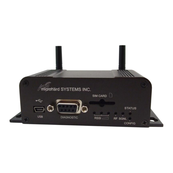
3.0 Hardware Description 3.1.1 IPn3G Mechanical Drawings IPn3G-ENC Top View Drawing 3-1: IPn3G Top View microhard SYSTEMS INC. SIM CARD STATUS DIAGNOSTIC RSSI RF SGNL CONFIG Drawing 3-2: IPn3G Front View ANTENNA RX DIV RS485/422 DATA ETHERNET Image 3-3: IPn3G Back View Notes: The dimension unit is inches. -
Page 20: Connectors & Indicators
3.0 Hardware Description 3.1.2 Connectors and Indicators 3.1.2.1 Front On the front of the IPn3G is the USB port, DIAGNOSTIC port, CONFIG Button, RSSI, STATUS, RF and SGNL LED’s as described below: microhard SYSTEMS INC. SIM CARD STATUS DIAGNOSTIC RSSI... -
Page 21: Rear
3.1.2 Connectors and Indicators 3.1.2.2 Rear On the back of the IPn3G is the Data port, RS485/422 interface, as well as the power connections. The unit also has the SMA(F) connectors for the Main (TX/RX), GPS and the Diversity (RX) antenna’s. -
Page 22: Webui Configuration
The Web User Interface (WebUI) is a browser based configuration method that allows a user to use a graphical interface to configure, test and troubleshoot a IPn3G unit. Any standard web browser can be used and no additional software is required. Using the Web User Interface a user can: ... -
Page 23: Logon Window
4.0 WebUI Configuration 4.1 Logon Window Upon successfully accessing the IPn3G using a Web Browser, the Logon window will appear. For security, do not allow the web browser Image 4-1: Logon Window to remember the User Name or Password. The factory default User Name is:... -
Page 24: System
4.0 WebUI Configuration 4.2 System 4.2.1 System > Summary The System Summary window displays an overview of the current IPn3G configuration. When initially logging into the unit, this will be the first window displayed, allowing a user to quickly identify configuration information. -
Page 25: Config
NTP time server parameters. As well as the Console and Wireless Traffic timeouts. Image 4-4: System Config Window Radio Description The Radio Description is simply a convenient identifier for a specific IPn3G, Values (Characters) e.g. Pump Station 5, 123 Main Street, etc. This feature is most welcome when accessing units remotely: a convenient cross-reference for the unit’s... - Page 26 = 2-digit minutes = 2-digit seconds Timezone The Timezone field allows you to set the time zone in the IPn3G. Select the Values (List) time zone from the dropdown list that matches your location. Time zones are sorted by UTC (+/-) offset.
- Page 27 The IPn3G can report system level events to a third party Syslog server, IP Address which can be used to monitor events reported by the IPn3G. The raw event syslog can be view by entering the following URL into the web browser 0.0.0.0...
-
Page 28: Location
The Location menu shows current modem location with online map and exact GPS Coordinate. If the GPS is not valid, it uses the Cell Tower ID that the unit is currently connect to, to approximate the general location of the IPn3G. Image 4-6: System > Location... -
Page 29: History
Max, Ave and Min links will show the raw data used to plots the points on the graphs. The data points are optionally stored in non-volatile (flash) memory, so data is saved even when the IPn3G is restarted or power is lost. -
Page 30: Network
4.3 Network 4.3.1 Network > Summary The Network > Summary tab gives an overview of the configuration of the Ethernet port on the IPn3G. This port is the RJ45 port located on the back of the IPn3G. Image 4-8: Network Configuration , Local IP Configuration Submenu Ethernet Port Status: The Ethernet port status shows the type and status of the local Ethernet Link. -
Page 31: Statistics
Ethernet port (hardware interface) on the rear of the IPn3G. Received and Transmitted information are applicable to the local data traffic into and out of the IPn3G, respectively. Errors which are counted include alignment, frame check sequence (FCS), frame too long, and internal MAC. -
Page 32: Graph
IPn3G. LAN (eth0) Shows an overview of all data sent or received by the IPn3G at the physical Ethernet port on the rear of the unit. A summary of the data of the current day and the current month is shown. -
Page 33: Config
4.3.4 Network > Config The Network > Config tab allows the configuration of the Ethernet port on the IPn3G (Rear RJ45). This port is configured as static port and must be configured by the user if the default values are not to be used. By default this port acts as a simple DHCP server, allowing the IPn3G to assign IP addresses and enable communication to attached devices. - Page 34 This is the amount of time a device can lease an IP Address from the Values (selection) IPn3G before it must renew or obtain a new IP address. This option allows the user to specify if the lease time specified in in seconds, minutes, hours Seconds etc.
- Page 35 00:00:00:00:00:00 Binding IP It may be desirable to ensure specific devices always obtain the same IP Values (IP Address) address from the DHCP service. Enter the IP Address to be assigned to that device here. 0.0.0.0 © Microhard Systems Inc.
-
Page 36: Static Routing
4.0 WebUI Configuration 4.3.5 Network > Static Routing The Network > Static Routing Menu, allows for the user to add static routes to the IPn3G. Static routes can be used to inform IPn3G of networks that are not directly attached. -
Page 37: Snmp
Custom MIBs can be obtained by contacting Microhard Systems Inc. Appendix F: SNMP MIB Sample con- tains the first few pages of the IPn3G MIB to be used as a reference The MIB file can change when new features are added, so it is best to contact us for the complete and latest MIB file for the IPn3G. - Page 38 SNMP queries. Being part of the community allows the SNMP agent to process SNMPv1 and SNMPv2c requests. This community name has only private READ/WRITE priority. SNMP V3 User Name Defines the user name for SNMPv3. Values (char string) V3user © Microhard Systems Inc.
- Page 39 Trap Community Name The community name which may receive traps. Values (char string) TrapUser Trap Manage Host IP Defines a host IP address where traps will be sent to (e.g. SNMP Values management system PC IP address). 0.0.0.0 © Microhard Systems Inc.
-
Page 40: Dhcp Lease
4.3.7 Network > DHCP Lease The Network > DHCP Lease tab shows a summary of IP Addresses assigned by the IPn3G’s DHCP server. As seen below the MAC address, IP Address, Name and the amount of time remaining on the DHCP lease is shown. -
Page 41: Local Monitor
The Local Device Monitor allows a user to monitor a local device connected locally to the Ethernet port or to the locally attached network. If the IPn3G cannot detect the specified IP or a DHCP assigned IP, the unit will restart the DHCP service, and eventually restart the modem to attempt to recover the connection. -
Page 42: Carrier
4.4 Carrier 4.4.1 Carrier > Statistics The Carrier Statistics window provides information related to the Wireless Carrier portion of the IPn3G. A variety of information can be found here, such as Activity Status, Network (Name of Wireless Carrier connected) , Data Service Type(2G/3G/HSPA etc), Frequency band, Phone Number etc. -
Page 43: Graph
The Carrier > Graph tab displays a graphical display of the Carrier Traffic on the Wireless interface of the IPn3G. WAN (ppp0) Shows an overview of all data sent or received by the IPn3G on the Wireless portion of the unit. A summary of the data of the current day and the current month is shown. -
Page 44: Config
Values (selection) manual selection of detected carriers, or the fixed selection of entering a carriers ID. Manual and Fixed are commonly used when the IPn3G is Automatic Roaming and it is desirable to control which carrier the unit connects to. - Page 45 Values (selection) networks. When disabled the router does not perform any address translation on the packets passing through it. Disable / Enable PPP Status This option allows the operation of PPP. Values (selection) Disable / Enable © Microhard Systems Inc.
-
Page 46: Authentication Type
IP pass-through allows the WAN IP address to be assigned to the device Values (selection) connected to the rear Ethernet port on the IPn3G. In this mode the IPn3G is transparent and forwards all traffic to the device connected to the Disable / Ethernet Ethernet port. -
Page 47: Dial Number
In most cases the IP will be read from the SIM card and this field should be left at the default value. 0.0.0.0 Use Remote DNS Enabled by default, the IPn3G, will use the DNS server as specified Values (Selection) automatically by the service provider. Disable / Enable Connect String Sets the modems connect string if required by the carrier. - Page 48 Domain This is the host or domain name for the IPn3G as assigned by the DDNS Values provider. user.dyndns.org User Name Enter a valid user name for the DDNS service selected above. Values...
- Page 49 4.0 WebUI Configuration Image 4-22: Carrier Configuration Menu, ICMP Keep Alive Check... ICMP Keep Alive Check This selection allows the use of a ICMP Keep Alive Check for the IPn3G. Values (selection) The default is disabled. Disable / Enable HostName...
-
Page 50: Com1 / Com2 Configuration
4.0 WebUI Configuration 4.5 COM1/COM2 4.5.1 COM1/2 > Statistics This window displays information related to the serial interfaces of the IPn3G. COM1/2 Port Status Enabled by default. (IF COM2 is disabled it is available as a ‘Console’ port.) ... -
Page 51: Config
Serial device data may be brought into a LAN network through TCP, UDP, or multicast; it may also exit the IPn3G network on another IPn3G ’s serial port. Ensure that the firewall allows access to the assigned ports by either creating rules to allow it, or by setting the WAN Request to allow. -
Page 52: Port Status
None / Hardware / CTS Framing handshaking, leave this setting at the default value of ‘None’. Software flow control When CTS Framing is selected, the IPn3G uses the CTS (XON/XOFF) is not signal to gate the output data on the serial port. Figure supported. - Page 53 Data Mode This setting defines the serial output data framing. In Transparent mode Values (default), the received data will be output promptly from the IPn3G. When set to Seamless, the serial port server will add a gap between data frames Seamless to comply with the MODBUS protocol for example.
- Page 54 Values (IP Address) disabled. If enabled the Modbus data will be encrypted with the Modbus Protection Key. Disable Enable Modbus TCP Protection Key MODBUS encryption key used for the MODBUS TCP Protection Status Values (UDP Port) feature. 1234 © Microhard Systems Inc.
- Page 55 Values (IP Address) this is a PC listening on the specified UDP port. 0.0.0.0 Logging Host Port Enter the UDP port of the IP Address where the data is to be sent. Values (UDP Port) 30001 © Microhard Systems Inc.
- Page 56 Default: 60 (seconds) TCP Server: In this mode, the IPn3G will not INITIATE a session, rather, it will wait for a Client to request a session of it (it’s being the Server—it ‘serves’ a Client). The unit will ‘listen’ on a specific TCP port. If a session is established, data will flow from the Client to the Server, and, if present, from the Server to the Client.
- Page 57 Multicast Port A UDP port that this IPn3G will send UDP packets to. The Multipoint (MP - see the UDP Point-to-Multipoint (MP) description) stations should be configured to listen to this point in order to receive multicast packets from this IPn3G.
- Page 58 A valid multicast address the unit is to listen to receive multicast UDP packets sent by another UDP Multipoint-to-Multipoint unit. Default: 224.1.1.1 Listening Multicast Port UDP port that the unit will listen to for multicast UDP packets sent by another UDP Multipoint- to-Multipoint unit. Default: 20011 © Microhard Systems Inc.
- Page 59 4.0 WebUI Configuration Protocol Config (continued) SMTP Client: If the IPn3G network has Internet access, this protocol may be used to send the data received on the serial port (COM1), in a selectable format (see Transfer Mode (below)), to an e-mail Both the SMTP Server and the e-mail addressee must be ‘reachable’...
- Page 60 SMS Transparent Mode: Serial data from the COM1 port can be send to one or multiple destinations via SMS text messaging. SMS messages received by the IPn3G can also be sent to the COM1 port. Image 4-27: COM > SMS Transparent Mode ...
- Page 61 AT+CMTI Stored SMS-DELIVER Indication Unsolicited Response GPS Transparent Mode: When in GPS Transparent Mode, GPS data is reported out of the serial port. Sample output is shown below: Image 4-28: COM > GPS Transparent Mode © Microhard Systems Inc.
- Page 62 Host/Server it retains a list of ModbusID’s and the respective IP/Port information required to communicate with any remotes. When a Modbus poll is received by the IPn3G it looks at the Modbus ID, then assembles a UDP packet to be sent to the corresponding IP/Port listed in the table. At the remote side, the packet is disassembled and sent out the remote serial port as original serial data.
-
Page 63: Host Port
Values (selection) select between Modbus RTU, Modbus ASCII, or as Broadcast (for other protocols. When set to broadcast the IPn3G will send any incoming serial RTU Modbus Direct Access data to all the IP/Port numbers listed. When in either Modbus mode the... -
Page 64: Usb Configuration
4.0 WebUI Configuration 4.6 USB 4.6.1 USB > Statistics This window displays information related to the USB port located on the front of the IPn3G. USB Port Status Displays the status of the USB Port. Configure via USB Configuration menu. -
Page 65: Config
4.0 WebUI Configuration 4.6.2 USB > Config The USB Device Port Mode allows a user to define the operation of the IPn3G ’s USB Port. The port can be configured to be used as any one of the following: Console Mode Provides support for the USB-to-Serial console port. - Page 66 Data Baud Rate for which the port is configured. For more information about any of the Data Port field pa- rameters refer to COM1/COM2 Configuration. Image 4-31: USB Configuration Data Port Values Console Mode Data Mode NDIS Mode © Microhard Systems Inc.
-
Page 67: Local Ip Address
Image 4-32: USB NDIS Network Configuration NDIS Mode In standalone Mode the USB port will act as a separate NIC for the IPn3G. Values (selection) In Bridge Mode the USB port wil use the same settings as the rear ethernet port. -
Page 68: Password
Console, and Telnet sessions) should be modified rather than retaining the factory default value of ‘admin’. The Upgrade Password protects the IPn3G from having firmware upgrade performed via FTP by an unauthorized person. It is recommended that the default password be changed when the system is deployed. -
Page 69: Security
Allows, or disables use of the DiscoverIP utility. The discover IP utility allows a user to scan a network for all available IPn3G units, and displays the MAC and IP addresses as well as the unit description. The port used Disable for Discovery is 20077. -
Page 70: Authentication
4.0 WebUI Configuration 4.7.4 Security > Authentication There are two methods whereby a user may be authenticated for access to the IPn3G: Local Using the Admin or Upgrade access and associated passwords - the authentication is done ‘locally’ within the IPn3G, and ... - Page 71 RADIUS User Name from your RADIUS secret Server Administrator.) nosecret Repeat RADIUS Secret See above. Re-enter RADIUS Secret in this field. Values Specific RADIUS Server secret nosecret RADIUS Timeout Amount of time to wait for RADIUS authentication. Values 1-65535 seconds © Microhard Systems Inc.
-
Page 72: Certificate Management
4.7.5 Security > Certificate Management When using the VPN features of the IPn3G, it is possible to select X.509 for the Authentication Type. If that is the case, the IPn3G must use the required x.509 certificates in order to establish a secure tunnel between other devices. -
Page 73: Firewall
WAN Request For best practices and to control data usage is When Blocked the IPn3G will block at traffic on the WAN (Wireless Carrier) Values critical that the firewall be unless specified otherwise in the Access Rules, MAC List, IP List configured properly. -
Page 74: Rules
ACCEPT will allow a connection, while REJECT (error) and DROP ACCEPT (quietly dropped), will refuse connections. REJECT DROP This is configured based on how the WAN Request and LAN to WAN Access Control are configured in the previous menus. © Microhard Systems Inc. - Page 75 Select the zone which is the intended destination of the data traffic. WAN Values (selection) applies to the wireless connection to the cellular carrier and the LAN refers to local connections on the IPn3G (Ethernet, USB NDIS etc) none Destination IP...
-
Page 76: Port Forwarding / Dmz
IP-Passthrough (Carrier > Config) is another option for passing traffic through the IPn3G, in this case all traffic is passed to the device connected to the RJ45 port of the IPn3G, The device must be set for DHCP, as the IPn3G assigns the WAN IP to the device, and the modem enters into a transparent mode, routing all traffic to the RJ45 port. - Page 77 Each Forward must have a unique rule name and can use up to 10 characters. Forward Internal Server IP Enter the IP address of the intended internal (i.e. on LAN side of IPn3G) Values (IP Address) server. 192.168.2.1 Internal Port Target port number of internal server on the LAN IP entered above.
-
Page 78: Mac List
MAC List configuration can be used to control which physical LAN devices can access the ports on the IPn3G, by restricting or allowing connections based on the MAC address. MAC List can be used alone or in combination with LAN to WAN Access Control to provide secure access to the physical ports of the IPn3G. -
Page 79: Ip List
4.8.4 Firewall > IP List IP List configuration can be used to define who or what can access the IPn3G, by restricting or allowing connections based on the IP Address/Subnet. Can be used alone or in combination with WAN Request and LAN to Wan Access Control. -
Page 80: Default
This menu provides a soft button which, when selected, will reset the firewall settings to factory defaults. Once the button is pressed all configured firewall settings will immediately be reset to factory defaults. Image 4-43: Reset Firewall to Default © Microhard Systems Inc. -
Page 81: Status
INPUT PINS Pin 7 on the Diagnostics port of the IPn3G can be used to detect an input. Pin 7 has a small wetting current (Vin) used to detect a contact closure, and prevent false readings by any noise or intermittent signals, it has a threshold sensitivity of 1.8V. -
Page 82: Advanced
The IPn3G supports VPN IPsec Gateway to Gateway (site-to-site) tunneling, meaning you are using the IPn3G to create a tunnel between two VPN devices. The IPn3G can also operate as a L2TP Server, allowing users to VPN into the unit from a remote PC, and a L2TP Client. - Page 83 The Site to Site configuration allows the connection of two VPN devices to create a tunnel, such as a IPn3G router at the office and a VPN capable router at a teleworker’s home. To establish a tunnel, settings must be mirrored on the two routers. A successful connection requires that at least one router is identifiable by a static IP address or a Server ID.
- Page 84 Define the local network by specifying the local subnet. Each end of the Values (IP Address) tunnel must be on different subnets. To setup/change the local subnet on the IPn3G, visit the Network Configuration Tab prior to setting up a VPN (no default) tunnel.
- Page 85 Server ID is required for the connection. The Server ID must be in the format @name, where name can be anything. Both routers must know (no default) each others names to establish a connection. © Microhard Systems Inc.
- Page 86 Select value to match the Phase 1 Authentication used by the remote VPN Values (selection) router. md5 / sha1 Phase 1 SA Life Time Select value to match the values required by the remote VPN router. Values 28800 © Microhard Systems Inc.
-
Page 87: Preshared Key
Values (characters) router. password DPD Delay Set the DPD Delay required to authenticate with the remote VPN router. Values (seconds) DPD Timeout Set the DPD Timeout required to authenticate with the remote VPN router. Values (seconds) © Microhard Systems Inc. -
Page 88: L2Tp Server
Values (selection) must be entered under IPsec Setup > Preshared Key. If X.509 is selected, Certificate Management (Security) must be used to load the required Preshared Key certificates and private keys related to X.509 X.509 CA © Microhard Systems Inc. - Page 89 Server ID must also be known. IP Only IP + Server ID Local Setup > Gateway IP Address Displays the current WAN IP address of the IPn3G, which is the local VPN Values (IP Address) Gateway. Current IP Address Server ID...
-
Page 90: L2Tp Client
4.0 WebUI Configuration 4.10.1.3 VPN > L2TP Client The IPn3G can also operate as a L2TP Client, allowing a VPN connection to be made with a L2TP Server. Image 4-50: VPN IPsec, VPN Client Submenu Add New Connection > Connection Name... - Page 91 Values (IP Address) (no default) Remote Setup > Subnet Mask Enter the subnet mask of the remote network. Values (IP Address) (no default) IPsec Setup - Refer back to the previous sections for information about IPsec parameters. © Microhard Systems Inc.
-
Page 92: Vpn Client Status
For VPN L2TP Server operation, users will be required to provide a username and password. Use VPN Client Status to set up the required users. Image 4-51: VPN IPsec, VPN Client Submenu Image 4-52: VPN IPsec, VPN Client Submenu © Microhard Systems Inc. -
Page 93: Gre Tunneling
4.0 WebUI Configuration 4.10.2 GRE The IPn3G also supports GRE (Generic Routing Encapsulation), which can encapsulate a wide variety of network layer protocols not supported by traditional VPN. This allows IP packets to travel from one side of a GRE tunnel to the other without being parsed or treated like IP packets. - Page 94 Each GRE tunnel must have a unique name. Up to 10 GRE tunnels are Values (chars(32)) supported by the IPn3G. Valid characters include A-Z, a –z, 1 - 0, ‘_’. Spaces and dashes are not allowed. GRE Tunnel Local Status Enable / Disable the GRE Tunnel.
- Page 95 4.0 WebUI Configuration Image 4-56: GRE > Local / Remote Setup Local Setup > Gateway IP Address Enter the current WAN IP address of the IPn3G. Values (IP Address) 0.0.0.0 Local Setup > GRE Tunnel IP Address This is the IP Address of the local GRE Tunnel, this must be in the same Values (IP Address) subnet as the remote GRE tunnel.
- Page 96 Specify the LAN subnet mask being used on the remote network. Values (IP Address) 0.0.0.0 Image 4-57: GRE > IPsec Setup The setup for GRE IPsec is identical to the setup of VPN IPsec, refer to the previous section for more information. © Microhard Systems Inc.
-
Page 97: Gps
4.10.3 Advanced > GPS Some models of the IPn3G support GPS and can provide GPS data to a client. The IPn3G can be polled for GPS data via GPSD standards and/or provide customizable reporting to up to 4 different destination IP addresses via UDP packets, or by Email. - Page 98 Enable or disable the GPS polling function of the IPn3G. The default is Values (selection) disabled. Disable / Enable TCP Port Specify the TCP port on the IPn3G running that a remote GPS system can Values (1-65535) connect and poll for GPSD information. 2947 Antenna Power (V) Specifies the output power supplied to the GPS antenna as required for the Values (1.5 - 3.05)
- Page 99 None None Message is not used, no data will be sent Sends all of the below GPS Fix Data Overall Satellite Data Detailed Satellite Data Recommended Min Data for GPS Vector Track & Ground Speed © Microhard Systems Inc.
- Page 100 Mail Recipient Enter the Email address of where the message is to be sent to. Values (Chars) varies Interval(s) The repeat timer specifies the frequency at which the GPS data is reported Values (seconds) in seconds. © Microhard Systems Inc.
- Page 101 None None Message is not used, no data will be sent Sends all of the below GPS Fix Data Overall Satellite Data Detailed Satellite Data Recommended Min Data for GPS Vector Track & Ground Speed © Microhard Systems Inc.
-
Page 102: Event Reporting
4.10.4 Advanced > Event Reporting Event Reporting allows the IPn3G to send periodic updates on the modem status via UDP packets. These packets are customizable and can be sent to up to 4 different IP Addresses, at a programmable interval. -
Page 103: Message Structure
*Default Port Numbers for Microhard NMS (20100 for modem events, 20200 for Management) Interval (s) This is the interval time in seconds, that the IPn3G will send the configured Values (seconds) UDP message to the Remote IP and Port specified. -
Page 104: Message Payload
If message type mask = 0x15, the eurd package will be equipped by header+modem information+carrier information+wanip information. If message type mask = 0x4, the eurd package will be equipped by header+carrier information. If message type mask = 0x11, the eurd package will be equipped by header+modem infomation+wanip infomation. © Microhard Systems Inc. -
Page 105: Sms
4.0 WebUI Configuration 4.10.5 Advanced > SMS The IPn3G supports SMS messaging through the serial port (See IP Protocol Config under COM1), Through AT Command via Serial and Telnet (See AT Commands), as well as SMS Alerts based on different conditions (See SMS Alerts). The Advanced > SMS menu allows a user to view the messages stored on the SIM card, and if desired to respond to messages from within the WebUI. -
Page 106: Sms Alerts
4.10.6 Advanced > SMS Alerts SMS Alerts can be setup in the IPn3G to report conditions that may affect the integrity of the communications to the modem. This can be used to get alerts before problems become critical and actions can be taken to correct any issues before a complete failure occurs. - Page 107 High: 7 - 36 (36) Low: 7 - 36 (7) Home / Roaming Status The IPn3G can be configured to send a warning when the unit changes Values (selection) roaming status. This can be critical as often roaming data rates are obscenely expensive.
-
Page 108: Netflow Report
4.10.7 Advanced > Netflow Report The IPn3G can be configured to send Netflow reports to up to 4 remote systems. Netflow is a tool that collects and reports IP traffic information, allowing a user to analyze network traffic on a per interface basis to identity bandwidth issues and to understand data needs. -
Page 109: Modbus
4.10.8 Advanced > Modbus 4.10.8.1 Modbus > TCP Modbus The IPn3G can be configured to operate as a TCP/IP or Serial (COM) Modbus slave and respond to Modbus requests and report various information as shown in the Data Map. Image 4-68: Advanced > Modbus TCP Setup Modbus Slave Status Disable or enable TCP and Serial Modbus services on the IPn3G. - Page 110 4.0 WebUI Configuration Port Enter the port number on the IPn3G in which to listen for incoming Modbus Values (Port #) messages. Active Timeout Define the active timeout in seconds. Values (seconds) Slave ID Each Modbus slave device must have a unique address, or Slave ID. Enter Values (value) this value here as required by the Modbus Host System.
-
Page 111: Com (Serial) Mobus
4.10.8.2 Modbus > COM (Serial) Modbus The IPn3G can also participate in serial based Modbus, to configure and view the serial Modbus settings, the COM1 port must first be disabled in the COM1 > Settings menu. Only the settings that are different from TCP Modbus will be discussed. - Page 112 4.0 WebUI Configuration 4.10.8.3 Modbus > Modbus Data Map Image 70: Advanced > Modbus Data Map © Microhard Systems Inc.
-
Page 113: Power Saving
4.0 WebUI Configuration 4.10.9 Advanced > Power Saving Various power saving options are available in the IPn3G. The IPn3G can be put into power saving mode by either using the input voltage, a simple timer, or by sensing incoming local data. -
Page 114: Data Usage
4.10.10 Advanced > Data Usage The Data Usage tool on the IPn3G allows users to monitor the amount of cellular data consumed. Since cellular devices are generally billed based on the amount of data used, alerts can be triggered by setting daily and/or monthly limits. - Page 115 Period Start Day For Monthly tracking, select the day the billing/data cycles begins. On this Values (1-31) day each month the IPn3G will reset the data usage monitor numbers. 1 (Day of Month) Phone Number If SMS is selected as the notification method, enter the phone number to...
- Page 116 Values (string) Email account used to send Emails. Most email servers require authentication on outgoing emails. Mail Recipient Enter the email address of the individual or distribution list to send the Values (xx@xx.xx) email notification to. host@ © Microhard Systems Inc.
-
Page 117: Tools
Selecting ‘Download’ affords the opportunity to download the various values to a “system.conf” text file. This file may be useful for reference or requested by Microhard Support to aid in any required troubleshooting or application analysis. The file can also be modified and uploaded back to the IPn3G, or used as a template. - Page 118 Image 4-76: Tools > Maintenance > Configuration Backup (FTP) From a DOS command prompt, start a FTP session with the IPn3G, you can FTP to the USB NDIS IP Address, the LAN IP Address, and if the firewall settings allow, the WAN IP Address. The example...
-
Page 119: Configuration Restore (Webui/Ftp)
4.0 WebUI Configuration 4.11.1.3 Restoring Configuration Settings A system.conf file can be uploaded to the IPn3G to restore previous settings or as a template to aid in configuration of multiple units that have similar settings. The filename must be “system.conf” or an error message will be reported by the IPn3G. - Page 120 Image 4-78: Tools > Maintenance > Configuration Backup (FTP) From a DOS command prompt, start a FTP session with the IPn3G, you can FTP to the USB NDIS IP Address (192.168.111.1), the LAN IP Address (192.168.0.1), and if the firewall settings allow, the WAN IP Address.
-
Page 121: Firmware Upgrade (Webui/Ftp)
Microhard Systems. Image 4-79: Tools > Maintenance > WebUI Firmware Upload Using the Erase Settings checkbox tells the IPn3G not to store the current configuration settings, there- fore once the upgrade process is complete the unit will have factory default settings... - Page 122 Image 4-80: Tools > Maintenance > Firmware Upgrade (FTP) From a DOS command prompt, start a FTP session with the IPn3G, you can FTP to the USB NDIS IP Address (192.168.111.1), the LAN IP Address (192.168.0.1), and if the firewall settings allow, the WAN IP Address.
-
Page 123: Nms Settings
Systems Inc. Using NMS you can monitor online/offline units, retrieve usage data, perform backups and centralized upgrades, etc. The following section describes how to get started with NMS and how to configure the IPn3G to report to NMS. To get started with NMS, browse to the Microhard NMS website, nms.microhardcorp.com, click on the register button in the top right corner to register for a Domain (profile), and set up a Domain Administrator Account. - Page 124 Once confirmed, this account will be the administrator of the domain. The administrator can manage sub- domain and user accounts that belong to this domain. Once NMS has been configured, each IPn3G must be configured to report into NMS. Image 4-82: Tools > NMS Settings...
-
Page 125: Default Settings
NMS Report Setting Carrier Location Enable or Disable location estimation via carrier connection. When Values (chars) enabled, the IPn3G will consume some data to retrieve location information from the internet if GPS data is not valid or available. Disable/Enable Report Status Enable or Disable UDP reporting of data to the NMS system. - Page 126 The IPn3G can report information about the different interfaces it has. By Values (check boxes) default the IPn3G is set to send information about the Carrier, such as usage and RSSI. Statistical and usage data on USB, Ethernet and Serial Ethernet interfaces can also be reported.
-
Page 127: Diagnostic Utilities (Ping/Trace Route)
4.0 WebUI Configuration 4.11.3 Tools > Diagnostic The Diagnostic menu provides Ping and Trace Route tools to use to test connectivity of the IPn3G. Image 4-83: Diagnostic Utilities A user can use the Ping command by entering the IP address of destination device in the Remote IP Address, use Count for the number of ping messages to send, and the Packet Size to modify the size of the packets sent. -
Page 128: Reset To Default
This feature is particularly useful for rebooting remote units and has the same effect as power cycling the unit. Using the supplied interface, It is also possible to reboot the IPn3G on a schedule. Up to 10 tasks can be added to reboot the IPn3G at specific intervals if required. Both the Hour and Minute parameters are required to ensure the feature works as intended. -
Page 129: Logout
4.0 WebUI Configuration 4.12 Logout The Logout menu allows a user to logout of the current session and brings up the logion prompt. Image 4-86: Logout Window © Microhard Systems Inc. -
Page 130: At Commands
System > Summary screen in the WebUI.). 5.1.1 Serial Port To connect and access the AT Command interface on the IPn3G, a physical connection must be made on the RS232 DB9 serial port on the front of the IPn3G labeled ‘Diagnostic’. A terminal emulation program (Hyperterminal, Tera Term, ProComm, Putty etc) can then be used to communicate with the IPn3G. -
Page 131: Telnet Tcp/Ip Configuration
5.1.2 Telnet (TCP/IP) Telnet can be used to access the AT Command interface of the IPn3G. The default port is TCP Port 23. A telnet session can be made to the unit using any Telnet application (Windows Telnet, Tera Term, ProComm etc). -
Page 132: At Command Syntax
5.0 AT Commands 5.2 AT Command Syntax The follow syntax is used when issuing AT Commands on the IPn3G All commands start with the AT characters and end with the <Enter> key Microhard Specific Commands start with +M Help will list top level commands (ATL will list ALL available AT Commands) To query syntax of a command: AT+<command_name>=? -
Page 133: Supported At Commands
Response: Command history: 0. ATL 1. AT? 2. AT=? 3. at 4. help 5. AT 7. ATL 8. ATH AT&R Description Command Syntax Read modem profile to editable profile. AT&R <enter> Example Input: AT&R <enter> Response: © Microhard Systems Inc. - Page 134 Command Syntax Read modem active profile. AT&V <enter> Example Input: AT&V <enter> Response: BASIC_SETTINGS_BEGIN: #Hardware Version:--Read Only Hardware_Version=v2.0.0 #Software Version:--Read Only Software_Version=v1.2.2-r1045c #Radio Version:--Read Only Radio_Version=0. #Radio Description: Radio_Description=IPn3G #Date(yyyy-mm-dd): System_Date=2012-02-01 #Time(hh:mm:ss): System_Time=10:41:25 <Additional Output Omitted> © Microhard Systems Inc.
- Page 135 ATA <enter> AT&W command Response: must be issued to save changes! IPn3G Login: Description Command Syntax Quit. Exits AT Command session and returns ATO <enter> you to login prompt. Example Input: ATA <enter> Response: IPn3G Login: © Microhard Systems Inc.
- Page 136 DNS2:64.71.255.253 Ethernet Port: IP Address:192.168.0.1 IP Subnet Mask:255.255.255.0 IP Gateway:192.168.0.1 Ethernet MAC:00:0F:92:00:40:9A USB Port:NDIS Mode Standalone Local IP Address:192.168.111.1 Subnet Mask:255.255.255.0 Host IP:192.168.111.2 USB MAC:00:0F:92:01:40:9A System: System time:Wed Feb 01 2012 16:42:03 Hardware Version:v2.0.0 Software Version:v1.2.2-r1045c © Microhard Systems Inc.
- Page 137 Input: (To set value) AT&W command AT+MMNAME=IPn3G_CLGY<enter> must be issued to save changes! Response: Input: (To retrieve value) AT+MMNAME=?<enter> Response: +MMNAME: IPn3G_CLGY AT+GMI Description Command Syntax Get Manufacturer Identification AT+GMI=<enter> Example Input: AT+GMI<enter> Response: +GMI: 2010-2011 Microhard Systems Inc. © Microhard Systems Inc.
- Page 138 Check modem’s IMEI and IMSI numbers. AT+CIMI <enter> Example Input: AT+CIMI <enter> AT&W command Response: must be issued to save +CIMI: IMEI:354626030256080,IMSI:302720406979607 changes! AT+CCID Description Command Syntax Check modem’s SIM card number. AT+CCID=<enter> Example Input: AT+CCID<enter> Response: +CCID: 89302720401025322275 © Microhard Systems Inc.
- Page 139 Reboots the modem. AT+MREB <enter> Example AT&W command Input: must be issued to save changes! AT+MREB <enter> Response: AT+MNTP Description Command Syntax Enable and define a NTP server. AT+MNTP=<status>,<NTP server> Status: Disable Enable Example Input: AT+MNTP=1,pool.ntp.org<enter> Response: © Microhard Systems Inc.
- Page 140 Example changes! Input: AT+MCNTO=300 <enter> Response: AT+MSDBE Description Command Syntax Enables/Disables the system default button AT+MNTP=<Mode> located on the front of the IPn3G (CONFIG) Mode: Disable Enable Example Input: AT+MSDBE=1 <enter> Response: © Microhard Systems Inc.
- Page 141 AT+MDHCP=1 <enter> changes! Response: AT+MDHCPA Description Command Syntax Define the Starting and Ending IP Address AT+MDHCPA=<Start IP>, <End IP> (range) assignable by DHCP on the local Ethernet interface. Example Input: AT+MDHCPA=192.168.0.100,192.168.0.200 <enter> Response: © Microhard Systems Inc.
- Page 142 Input: changes! AT+MUMAC<enter> Response: +MUMAC: "00:0F:92:01:40:9A" AT+MUDPM Description Command Syntax Set the operating mode of the USB port. AT+MUDPM=<mode> 0 - Console Mode 1 - Data Mode 2 - NDIS Mode Example Input: AT+MUDPM=2 <enter> Response: © Microhard Systems Inc.
- Page 143 3 - 2400 4 - 3600 Example 5 - 4800 6 - 7200 7 - 9600 Input: 8 - 14400 AT+MUDBR=13 <enter> 9 - 19200 Response: 10 - 28800 11 - 38400 12 - 57600 13 - 115200 © Microhard Systems Inc.
- Page 144 0 - Seamless 1 - Transparent AT&W command must be issued to save Example changes! Input: AT+MUDDM=1<enter> Response: AT+MUDCT Description Command Syntax Set USB data port character timeout AT+MUDCT=<Timeout_s> 0 - 65535 (seconds) Example Input: AT+MUDCT=0 <enter> Response: © Microhard Systems Inc.
- Page 145 2 - High Example AT&W command must be issued to save Input: changes! AT+MUDPL=0<enter> Response: AT+MUDNCDI Description Command Syntax Enable/Disable USB data port no-connection AT+MUDNCDI=<mode> data intake. 0 - Disable 1 - Enable Example Input: AT+MUDNCDI=1 <enter> Response: © Microhard Systems Inc.
- Page 146 6 - UDP Multipoint to Multipoint Response: AT+MUDTC Description Command Syntax Set USB data port TCP Client configuration, AT+MUDTC=<Remote Server IP>, when set to TCP Client mode. <Remote Server Port>, <Outgoing Connection Timeout> Example Input: AT+MUDTC=192.168.0.189,20001,60 <enter> Response: © Microhard Systems Inc.
- Page 147 0 - Monitor 1 - Multi-polling Example Input: (Entering Values) AT+MUDTCS=0.0.0.0,20003,60,0,100,20003,300 <enter> Response: Input: (Retriieving Values) AT+MUDTCS?<enter> Response: +MUDTCS: Remote Server IP Address:0.0.0.0,Remote Server Port:20003,Outgoing Conn ection Timeout:60,TCP Server Polling Mode:Monitor,Multi-polling Timeout(ms):100, Local Listening Port:20003,Incoming Connection Timeout:300 © Microhard Systems Inc.
- Page 148 IP protocol is set to Port>, <Listener Port>, <Time to live> UDP point to multipoint (P) Example Input: (Entering Values) AT+MUDUPMP=224.1.1.3,20003,20013,1 <enter> Response: Input: (Retriieving Values) AT+MUDUPMP?<enter> Response: +MUDUPMP: Multicast IP Address:224.1.1.3,Multicast Port:20003,Listening Port:200 13,Time to Live:1 © Microhard Systems Inc.
- Page 149 <Multicast Port>, <Time to live>, <Listen to UDP multipoint to multipoint. Multicast IP>, <Listen Multicast Port> Example Input: (Entering Values) AT+MUDUMPMP=224.1.1.3,20013,1,224.1.1.3,20013 <enter> Response: Input: (Retriieving Values) AT+MUDUMPMP?<enter> Response: +MUDUMPMP: Multicast IP Address:224.1.1.3,Multicast Port:20013,Time to Live:1,Li sten Multicast IP Address:224.1.1.3,Listen Multicast Port:20013 © Microhard Systems Inc.
- Page 150 AT+MAUTH=0,0.0.0.0,1812,nosecret,10 <enter> Response: Input: (Retriieving Values) AT+MAUTH?<enter> Response: +MAUTH: Local,"0.0.0.0","1812","nosecret",10 AT+MDISS Description Command Syntax Configure discovery mode service used by AT+MDISS=<Mode> IPn3G and utilities such as “IP Discovery”. Mode: Disable Discoverable Changeable Example Input: AT+MDISS=1 <enter> Response: © Microhard Systems Inc.
- Page 151 Command Syntax Enable/Disable PPP AT+MPPPS=<Mode> Mode: Disable Enable AT&W command must be issued to save Example changes! Input: AT+MPPPS=1 <enter> Response: AT+MPIPP Description Command Syntax Enable/Disable IP-Passthrough AT+MPIPP=<Mode> Mode: Disable Ethernet Example Input: AT+MPIPP=1 <enter> Response: © Microhard Systems Inc.
- Page 152 Example changes! Input: AT+MPITO=0 <enter> Response: AT+MPCTO Description Command Syntax The maximum amount of time to wait for a AT+MPCTO=<Value> connection The default is 90 seconds. 0 - 65535 seconds Example Input: AT+MPCTO=90<enter> Response: © Microhard Systems Inc.
- Page 153 CHAP - Challenge Handshake Authentication must be issued to save Protocol. pap-chap changes! Example Input: AT+MPAT=2 <enter> Response: AT+MPUP Description Command Syntax Enter login credentials for connection to the AT+MPUP=<user name>, <password> wireless carrier. Example Input: AT+MPUP=4035558709@carrier.isp, 35&HJ345<enter> Response: © Microhard Systems Inc.
- Page 154 Response: changes! AT+MAPN Description Command Syntax Sets the Access Point Name (APN). Required AT+MAPN=<access point name> and assigned by the wireless carrier. Example Input: (Enter value) AT+MAPN=myapn.isp.com <enter> Response: Input: (Retrieve value) AT+MAPN?<enter> Response: +MAPN: myapn.isp.com © Microhard Systems Inc.
- Page 155 Example Input: AT+MWSIP=0.0.0.0 <enter> Response: AT+MURD Description Command Syntax Enable/Disable remote DNS. Enabled by AT+MURD=<Mode> default, the IPn3G, will use the DNS server as Mode: specified automatically by the service provider. Disable Enable Example Input: AT+MURD=1 <enter> Response: © Microhard Systems Inc.
- Page 156 0 - dyndns.org AT&W command 1 - changeip.com must be issued to save changes! 2 - zoneedit.com 3 - no-ip.com 4 - noip.com 5 - freedns.afraid.org 6 - dnsmax.com 7 - thatip.com Example Input: AT+MDDNS=0,user.dydns.org,user,password <enter> Response: © Microhard Systems Inc.
- Page 157 AT+MIKACE=<Mode> check. Mode: Disable Enable Example Input: AT+MIKACE=1<enter> Response: AT+MIKAC Description Command Syntax Set ICMP Keep-alive check parameters. AT+MIKAC=<host name>, <interval in seconds>, <count> AT&W command Example must be issued to save changes! Input: AT+MIKAC=www.google.com,600,10<enter> Response: © Microhard Systems Inc.
- Page 158 Input: AT+MCOCM=0 <enter> Response: AT+MCOBR Description Command Syntax Set COM1 port baud rate. AT+MCOBR=<Baud Rate> Baud Rate: 57600 115200 Example 1200 230400 2400 Input: 460800 AT+MCOBR=7<enter> 3600 921600 Response: 4800 7200 9600 14400 19200 28800 38400 © Microhard Systems Inc.
- Page 159 AT+MCOFC=0 <enter> must be issued to save Response: changes! AT+MCOPRDD Description Command Syntax Set COM1 port pre-data delay (ms) AT+MCOPRDD=<delay_ms> Example Input: AT+MCOPRDD=100<enter> AT+MCOPODD Description Command Syntax Set COM1 port post-data delay (ms) AT+MCOPODD=<delay_ms> Example Input: AT+MCOPODD=100<enter> © Microhard Systems Inc.
- Page 160 Description Command Syntax Set COM1 port character timeout. AT+MCOCT=<timeout_s> Example AT&W command Input: must be issued to save AT+MCOCT=0 <enter> changes! Response: AT+MCOMPS Description Command Syntax Set COM1 maximum packet size. AT+MCOMPS=<size> Example Input: AT+MCOMPS=1024<enter> Response: © Microhard Systems Inc.
- Page 161 Enable must be issued to save changes! Example Input: AT+MCONCDI=0 <enter> Response: AT+MCOMTC Description Command Syntax Set COM1 modbus TCP configuration AT+MCOMTC=<Status>, <Protection status>, <Protection Key> Status and Protection Status: Disable Enable Example Input: AT+MCOMTC=0,0,1234<enter> Response: © Microhard Systems Inc.
- Page 162 AT+MCOTC=0.0.0.0,20001,60 <enter> Response: AT+MCOTS Description Command Syntax Set COM1 TCP Server parameters when AT+MCOTS=<Polling Mode>, <Polling configured as TCP Server mode. timeout_s>, <Local Listener Port>, <Connection timeout_s> Polling Mode: Example Monitor Input: Multi-polling AT+MCOTS=0,100,20001,300 <enter> Response: © Microhard Systems Inc.
- Page 163 AT+MCOUPMP Description Command Syntax Set COM1 UDP Point-to-Multipoint as point AT+MCOUPMP=<Multicast IP>, <Multicast parameters when configured in UDP Point-to- Port>, <Listener Port>, <Time to live> Multipoint (P) mode. Example Input: AT+MCOUPMP=224.1.1.1, 20001, 20001, 1 <enter> Response: © Microhard Systems Inc.
- Page 164 Set COM1 SMTP Client Configuration when AT+MCOSMTP=<Mail Subject>, <Mail set to SMTP Client mode. Server>, <Mail Recipient>, <Message Max Size>, <Timeout_s>, <Transfer Mode> Transfer Mode: Text Attached File Hex Code Example Input: AT+MCOSMTP=COM1 Message, mail.mymail.com, host@email.com, 1024, 10, 0<enter> Response: © Microhard Systems Inc.
- Page 165 Input: AT+MCOPPP=192.168.0.1,192.168.0.99,30<enter> Response: AT+MCTPS Description Command Syntax Enable/Disable the COM2 serial port. This port AT+MCTPS=<Mode> is located on the front of the IPn3G and is Mode: labelled as the DIAGNOSTIC port. Disable Enable Example AT&W command must be issued to save...
- Page 166 Command Syntax Set COM2 data mode. AT+MCTDM=<Data Mode> Data Mode: Seamless AT&W command Transparent must be issued to save changes! Example Input: AT+MCTDM=1<enter> Response: AT+MCTCT Description Command Syntax Set COM2 character timeout. AT+MCTCT=<timeout_s> Example Input: AT+MCTCT=0<enter> Response: © Microhard Systems Inc.
- Page 167 Set COM2 port priority. AT+MCTP=<Mode> Mode: Normal Medium High Example AT&W command must be issued to save Input: changes! AT+MCTP=0<enter> Response: AT+MCTNCDI Description Command Syntax Enable/Disable COM2 port no-connection data AT+MCTNCDI=<Mode> intake. Mode: Disable Enable Example Input: AT+MCTNCDI=1<enter> Response: © Microhard Systems Inc.
- Page 168 UDP Point to Multipoint(MP) UDP Multipoint to Multipoint AT+MCTTC Description Command Syntax Set COM2 TCP Client parameters when IP AT+MCTTC=<Remote Server IP>, Protocol Mode is set to TCP Client. <Remote Server Port>, <Outgoing timeout_s> Example Input: AT+MCTTC=0.0.0.0,20002,60<enter> Response: © Microhard Systems Inc.
- Page 169 Multi-polling Response: AT+MCTUPP Description Command Syntax Set COM2 UDP Point-to-Point parameters AT+MCTUPP=<Remote Server IP>, when IP Protocol is set to UDP Point-to-Point <Remote Server Port>, <Liste mode. ner Port>, <UDP timeout_s> Example Input: AT+MCTUPP=0.0.0.0,20002,20002,10<enter> Response: © Microhard Systems Inc.
- Page 170 Response: AT+MCTUMPMP Description Command Syntax Set COM2 UDP Multipoint-to-Multipoint AT+MCTUMPMP=<Multicast IP>, parameters when IP Protocol is set to UDP <Multicast Port>, <Time to live>, <Listen Multipoint-to-Multipoint mode. Multicast IP>, <Listen Multicast Port> Example Input: AT+MCTUMPMP=224.1.1.2,20012,1,224.1.1.2,20012<enter> Response: © Microhard Systems Inc.
- Page 171 “REC READ” Received read messages <oa> Originator Address String type <dt> Discharge Time String format: "yy/MM/dd,hh:mm:ss±zz" (year [00-99]/ month [01-12]/Day [01-31], Hour:Min:Second and TimeZone [quarters of an hour]) <data> SMS User Data in Text Mode String type © Microhard Systems Inc.
- Page 172 The messages are read from 0 - Lists all unread messages the SIM card memory. 1 - Lists all read messages 4 - Lists all messages Example Input: AT+CMGL=0 <enter> Response: +CMGR: "REC READ","+14035555776",,"2012/02/06,10:39:43-07" This is the SMS message. © Microhard Systems Inc.
- Page 173 <index>, or multiple delflag: messages according to <delflag>. 0 - Deletes the message specified in <index> 1 - Deletes all read messages 4 - Deletes all messages Example Input: AT+CMGD=0,4 <enter> Response: index=0 dflag=4 © Microhard Systems Inc.
- Page 174 Example Input: AT+MOS=0 <enter> Response: +MOS: available output status OUTPUT 1: 0 open ——————————————————————————— Input: AT+MOS=1,1,1 <enter> Response: +MOS: Set OUTPUT 1 : 1 close ——————————————————————————— Input: AT+MOS=1,1,0 <enter> Response: +MOS: Set OUTPUT 1: 0 open © Microhard Systems Inc.
-
Page 175: Command Syntax
UDP point to multipoint(MP) AT+MUDUMPMP Set usb data port UDP multipoint to multipoint configuration when IP protocol mode be set to UDP multipoint to multipoint AT+MPWD Set password AT+MAUTH Set authentication used by the modem © Microhard Systems Inc. - Page 176 Set com2 port IP protocol mode AT+MCTTC Set com2 port tcp client configuration when IP protocol mode be set to TCP Client AT+MCTTS Set com2 port tcp server configuration when IP protocol mode be set to TCP Server © Microhard Systems Inc.
- Page 177 Read SMS with changing status AT+MMGR Read SMS without changing status AT+CMGL List SMSs with changing status AT+MMGL List SMSs without changing status AT+CMGD Delete SMS AT+MIS Module Digital Input status AT+MOS Module Digital Output status and setting © Microhard Systems Inc.
-
Page 178: Appendix A: Rs485 Wiring
Figure C1 illustrates a typical 2-wire RS485 wiring configuration. The cable pair is shared for both transmit and receive data: it is very important that the IPn3G seize control of the line at the proper time when it is to transmit data. -
Page 179: Appendix B: Serial Interface
(DCE); the module transmits data on the RX line, and receives on TX. “DCE” and “module” are often synonymous since a module is typically a DCE device. “DTE” is, in most applications, a device such as a host microprocessor. © Microhard Systems Inc. -
Page 180: Appendix C: Ip-Passthrough
IPn3G (With exception of port 80, which is retained for remote configuration (configurable). Also, any traffic that is sent to the RJ45 port is sent directly out the WAN port and is not processed by the IPn3G. IP-Passthrough is ideal for applications where only a single device is connected to the IPn3G, and other features of the IPn3G are not required. - Page 181 IPn3G. On this PC a simple apache web server is running to illustrate a functioning system. On a remote PC, enter the WAN IP Address of the IPn3G into a web browser. As seen below, when the IP Address of the IPn3G is entered, the data is passed through to the attached PC.
-
Page 182: Appendix D: Port Forwarding
Step 1 Log into the IPn3G (Refer to Quick Start), and ensure that the Firewall is enabled. This can be found under Firewall > General. Also ensure that either WAN Request is set to Allow, which allows traffic to come in from the WAN, or that sufficient Rules or IP lists have been setup to allow specific traffic to pass through the IPn3G. - Page 183 GUI for all the devices on the LAN is the same, this is fine because they are located on different IP addresses, and the different external ports mapped by the IPn3G (80, 8080, 8081, 8082), will send the data to the intended destination.
-
Page 184: Appendix E: Vpn Example
Firewall > General. Also ensure that either WAN Request is set to Allow, which allows traffic to come in from the WAN, or that sufficient Rules or IP lists have been setup to allow specific traffic to pass through the IPn3G. Once that is complete, remember to “Apply”... - Page 185 Appendix E: VPN Example Step 3 Add a VPN Gateway to Gateway tunnel on each IPn3G. Site A Site B A.B.C.D E.F.G.H Must Match! Step 4 Submit changes to both units. It should be possible to ping and reach devices on either end of the VPN tunnel if both devices have been configured correctly and have network connectivity.
- Page 186 Step 1 Log into the IPn3G (Refer to Quick Start), and ensure that the Firewall is enabled. This can be found under Firewall > General. Also ensure that either WAN Request is set to Allow, which allows traffic to come in from the WAN, or that sufficient Rules or IP lists have been setup to allow specific traffic to pass through the IPn3G.
- Page 187 Appendix E: VPN Example Step 3 Add and configure a Gateway to Gateway VPN tunnel for the IPn3G. © Microhard Systems Inc.
- Page 188 Appendix E: VPN Example Step 4 Using Cisco ASDM configure the ASA 5505: © Microhard Systems Inc.
- Page 189 Appendix E: VPN Example Step 4 (continued…) © Microhard Systems Inc.
- Page 190 Appendix E: VPN Example Step 4 (continued…) © Microhard Systems Inc.
- Page 191 10 retry 2 crypto map outside_map 2 match address outside_cryptomap_1 crypto map outside_map 2 set peer 173.181.197.156 crypto map outside_map 2 set ikev1 transform-set test nat (inside,outside) 2 source static NETWORK_OBJ_192.168.30.0_24 NETWORK_OBJ_192.168.30.0_24 destination static NETWORK_OBJ_192.168.0.0_24 NETWORK_OBJ_192.168.0.0_24 no-proxy-arp route-lookup © Microhard Systems Inc.
-
Page 192: Appendix F: Firewall Example
Step 1 Log into the IPn3G (Refer to Quick Start). Navigate to the Firewall tab as shown below and ensure that the Firewall is turned on by enabling the Firewall Status. Next block all WAN traffic by setting the WAN Request to Block, and disable Remote Management. - Page 193 Test the connections. The IPn3G should only allow connections to the port specified from the Host A. An alternate means to limit connections to the IPn3G to a specific IP would have been to use the IP List Tool. By using Rules, we can not only limit specific IP’s, but we can also specify ports that can be used by an allowed IP address.
-
Page 194: Appendix G: Troubleshooting
Question: How do I reset my modem to factory default settings? Answer: If you are logged into the IPn3G navigate to the Tools > Default Tab. If you cannot log in, power on the IPn3G and wait until the status LED in on solid (not flashing). Press and hold the CONFIG button until the unit reboots (about 8 seconds). - Page 195 Answer: To access devices behind the IPn3G remotely, several methods can be used: A. IP Passthrough - The IPn3G is transparent and the connected device can be access directly. Refer to The IP-Passthrough Appendix for a detailed example of how this may be deployed.
- Page 196 Question: Why does my modem reset every 10 minutes (or other time)? Answer: There are a number of processes in the IPn3G that ensure that the unit is communicating at all times, and if a problem is detected will reboot the modem to attempt to resolve any issues: 1.
-
Page 197: Appendix H: "System.conf" File Structure
Appendix H: “system.conf” File Structure (1 of 25) The following pages show an example “system.conf” file exported from a IPn3G running Software Version v1.2.2-r1045d, file may change as features are added or modified. BASIC_SETTINGS_BEGIN: #Hardware Version:--Read Only Hardware_Version=v2.0.0 #Software Version:--Read Only Software_Version=v1.2.2-r1045c... - Page 198 P - 460800 Q - 921600 COM1_Data_Baud_Rate=H #Data Format: A - 8N1 B - 8N2 C - 8E1 D - 8O1 E - 7N1 F - 7N2 G - 7E1 H - 7O1 I - 7E2 J - 7O2 COM1_Data_Format=A © Microhard Systems Inc.
- Page 199 D - UDP Point to Point E - UDP Point to Multipoint(P) F - UDP Point to Multipoint(MP) G - UDP Multipoint to Multipoint COM2_IP_Protocol=F #USB Device Port Mode: A - Console Mode B - Data Mode C - NDIS Mode USB_Device_Mode=C © Microhard Systems Inc.
- Page 200 #DHCP Server Status: A - Disable B - Enable NetWork_DHCP_Server_Status=B #DHCP Server Subnet: NetWork_DHCP_Server_Subnet=192.168.0.0 #DHCP Server Netmask: NetWork_DHCP_Server_Netmask=255.255.255.0 #DHCP Starting Address: NetWork_DHCP_Start_Address=192.168.0.100 #DHCP Ending Address: NetWork_DHCP_End_Address=192.168.0.200 #Gateway Address: NetWork_DHCP_Gateway_Address=192.168.0.1 NetWork_DHCP_DNS_Address=0.0.0.0 #WINS Address: NetWork_DHCP_Wins_Address=0.0.0.0 #New Binding MAC: NetWork_DHCP_Binding_MAC=00:00:00:00:00:00 #New Binding IP: NetWork_DHCP_Binding_IP=0.0.0.0 © Microhard Systems Inc.
- Page 201 NetWork_SNMP_Trap_Manage_Host=0.0.0.0 #SNMP Listening Protocol: A - UDP B - TCP NetWork_SNMP_Listening_Protocol=A #SNMP Listening Port: NetWork_SNMP_Listening_Port=161 #Spanning-Tree Protocol Status: A - On B - Off NetWork_Bridge_STP_Status=A #Quality of Service Status: A - Disable B - Enable NetWork_QoS_Status=A © Microhard Systems Inc.
- Page 202 Radio_Static_IP_Addr= #Caller Acknowledgement: Radio_WakeOnCall_CallerID= Radio_WakeOnCall_CallerAck= #PowerOn Init String: Radio_PowerOn_InitStr= #Remote Server IP Address: COM1_T_Client_Server_Addr=0.0.0.0 #Remote Server Port: COM1_T_Client_Server_Port=20001 #Outgoing Connection Timeout: COM1_T_Client_Timeout=60 #TCP Server Polling Mode: A - Monitor B - Multi-polling COM1_T_Server_Polling_Mode=A #Multi-polling Timeout(ms): COM1_T_Server_Polling_Timeout=100 © Microhard Systems Inc.
- Page 203 #Multicast IP Address: COM1_UM_M_Multicast_Addr=224.1.1.1 #Multicast Port: COM1_UM_M_Multicast_Port=20001 #Multicast IP Address: COM1_UMTOM_Multicast_Addr=224.1.1.1 #Multicast Port: COM1_UMTOM_Multicast_Port=20011 #Time to Live: COM1_UMTOM_Multicast_TTL=1 #Listen Multicast IP Address: COM1_UMTOM_Listen_Multicast_Addr=224.1.1.1 #Listen Multicast Port: COM1_UMTOM_Listen_Multicast_Port=20011 #Mail Subject: COM1_SMTP_Mail_Subject=COM1 Message #Mail Server (IP/Name): COM1_SMTP_Server=0.0.0.0 #Mail Recipient: COM1_SMTP_Recipient=host@ © Microhard Systems Inc.
- Page 204 COM2_T_S_Listen_Port=20002 #Incoming Connection Timeout: COM2_T_S_Timeout=300 #Remote IP Address: COM2_U_PtoP_R_Addr=0.0.0.0 #Remote Port: COM2_U_PtoP_R_Port=20002 #Listening Port: COM2_U_PtoP_L_Port=20002 #UDP Timeout(s): COM2_U_PtoP_Timeout=10 #Multicast IP Address: COM2_UM_P_Multicast_Addr=224.1.1.2 #Multicast Port: COM2_UM_P_Multicast_Port=20002 #Listening Port: COM2_UM_P_Listen_Port=20012 #Time to Live: COM2_UM_P_TTL=1 #Remote IP Address: COM2_UM_M_Remote_Addr=0.0.0.0 © Microhard Systems Inc.
- Page 205 #HTTP Port: UI_Access_HTTP_Port=80 #HTTPS Port: UI_Access_HTTPS_Port=443 #Telnet Port: UI_Access_Telnet_Port=23 #SSH Port: UI_Access_SSH_Port=22 #Auth Mode: A - Local B - RADIUS&Local AUTH_Mode=A #RADIUS Server IP: AUTH_Server_IP=0.0.0.0 #RADIUS Server Port: AUTH_Server_Port=1812 #RADIUS Secret: AUTH_Seceret=nosecret #Repeat RADIUS Secret: AUTH_Repeat_Seceret=nosecret © Microhard Systems Inc.
- Page 206 #Select Rule Number: FW_Rule_Number=0 #Internal Server IP: FW_Portfw_Server_IP=192.168.2.5 #Internal Port: FW_Portfw_Internal_Port=0 #Protocol: A - TCP B - TCP:SYN C - UDP D - ICMP E - IPP2P F - IPP2P:UDP G - IPP2P:all H - All FW_Portfw_Protocol=A © Microhard Systems Inc.
- Page 207 #Packet Size: Tool_Ping_Packet_Size=32 #Trace Route Tool_TraceRoute=www.google.ca #VLAN ID (2-4094): VLAN_ID=2 #Description: VLAN_Description= #Port: A - Wired Port (eth0) B - Wireless Port (ppp0) VLAN_Seting_Port=A #VLAN (VLAN ID): VLAN_Setting_VLAN_ID=1 #Port Status: A - Disable B - Enable USB_Port_Status=A © Microhard Systems Inc.
- Page 208 USB_T_Client_Timeout=60 #TCP Server Polling Mode: A - Monitor B - Multi-polling USB_T_Server_Polling_Mode=A #Multi-polling Timeout(ms): USB_T_Server_Polling_Timeout=100 #Local Listening Port: USB_T_S_Listen_Port=20003 #Incoming Connection Timeout: USB_T_S_Timeout=300 #Remote IP Address: USB_U_PtoP_R_Addr=0.0.0.0 #Remote Port: USB_U_PtoP_R_Port=20003 #Listening Port: USB_U_PtoP_L_Port=20003 #UDP Timeout(s): USB_U_PtoP_Timeout=10 © Microhard Systems Inc.
- Page 209 #Modbus TCP Protection Status: A - Disable B - Enable COM2_Modbus_Protect_Status=A #Modbus TCP Protection Key: COM2_Modbus_Protect_Key=1234 #Modbus TCP Protection Status: A - Disable B - Enable USB_Modbus_Protect_Status=A #Modbus TCP Protection Key: USB_Modbus_Protect_Key=1234 #DDNS Status: A - Disable B - Enable DDNS_Status=A © Microhard Systems Inc.
- Page 210 #Tunnel Name: VPN_Tunnel_Name=tunnel #Tunnel Type: VPN_Tunnel_Type=0 #Tunnel Status: A - Disable B - Enable VPN_Tunnel(s)_Status=B #Tunnel No.: VPN_Tunnel_S2S_No=0 #Tunnel(s) Used: VPN_S2S_Tunnel(s)_Used=0 #Tunnel(s) Enabled: VPN_S2S_Tunnel(s)_Enabled=0 #Tunnel(s) Defined: VPN_S2S_Tunnel(s)_Defined=0000000000000000000 #Edit Tunnel No.: VPN_S2S_Tunnel_EDITING=100 #Tunnel No.: VPN_Tunnel_C2S_No=0 #Tunnel(s) Used: VPN_C2S_Tunnel(s)_Used=0 © Microhard Systems Inc.
- Page 211 #Phase 1 DH Group: A - modp1024 B - modp1536 C - modp2048 VPN_Phase1_DH_Group=A #Phase 1 Encryption: A - 3des B - aes C - aes128 D - aes256 VPN_Phase1_Encryption=A #Phase 1 Authentication: A - md5 B - sha1 VPN_Phase1_Authentication=A #Phase 1 SA Life Time: VPN_Phase1_SA_Life_Time=28800 © Microhard Systems Inc.
- Page 212 #Confirm New Password: VPN_VCA_User_RepeatPasswd= #Report# A - Disable B - Enable AGCR_Remote_Reporting_Status=AAAA #Remote IP: AGCR_Remote_IP_address0=0.0.0.0 #Remote IP: AGCR_Remote_IP_address1=0.0.0.0 #Remote IP: AGCR_Remote_IP_address2=0.0.0.0 #Remote IP: AGCR_Remote_IP_address3=0.0.0.0 #Remote Port: AGCR_Remote_PORT0=0 #Remote Port: AGCR_Remote_PORT1=0 #Remote Port: AGCR_Remote_PORT2=0 #Remote Port: AGCR_Remote_PORT3=0 © Microhard Systems Inc.
- Page 213 AGCR_Message_type3=AAAA #Report# A - Disable B - Modem_Event C - SDP_Event Event_Remote_Reporting_Status=AAAA #Remote IP: Event_Remote_IP_address0=0.0.0.0 #Remote IP: Event_Remote_IP_address1=0.0.0.0 #Remote IP: Event_Remote_IP_address2=0.0.0.0 #Remote IP: Event_Remote_IP_address3=0.0.0.0 #Remote Port: Event_Remote_PORT0=0 #Remote Port: Event_Remote_PORT1=0 #Remote Port: Event_Remote_PORT2=0 #Remote Port: Event_Remote_PORT3=0 © Microhard Systems Inc.
- Page 214 #Peer IP Address: GRE_Tunnel_DPD_IP=0.0.0.0 #Delay(s): GRE_Tunnel_DPD_Delay=30 #Timeout(s): GRE_Tunnel_DPD_Timeout=120 #Action: A - Hold_Tunnel B - Disable_Tunnel C - Delete_Tunnel GRE_Tunnel_DPD_Action=A #Local GRE Tunnel IP ddress: GRE_Tunnel_Local_IP=0.0.0.0 #Net Mask: GRE_Tunnel_Local_Netmask=0.0.0.0 #Local WAN IP Address: GRE_Tunnel_Local_WAN_IP=0.0.0.0 #Subnet IP Address: GRE_Tunnel_Remote_SubIP=0.0.0.0 © Microhard Systems Inc.
- Page 215 GRE_Preshared_Key=password #DPD Delay(s): GRE_DPD_Delay=32 #DPD Timeout(s): GRE_DPD_Timeout=122 #DPD Action: A - hold B - clear GRE_DPD_Action=A #GRE Ipsec Status: A - Disconnected B - Connected GRE_IPSEC_STATUS=A #Dead Peer Detection: A - Disable B - Enable GRE_DPD_Status=A © Microhard Systems Inc.
- Page 216 #SMS SM Total: SMS_SM_TOTAL= #SMS SM Used: SMS_SM_USED= #SMS ME Total: SMS_ME_TOTAL= #SMS ME Used: SMS_ME_USED= #Alert A - Disable B - Enable SAL_Enable=A RSSI_CHECK=A #Low Threshold(dBm): RSSI_LOW=-99 #Core Temperature CORE_TEMPERATURE_CHECK=A #High Threshold(°C): CTEMP_HIGH=80 #Low Threshold(°C): CTEMP_LOW=20 © Microhard Systems Inc.
- Page 217 #Interface: A - LAN B - WAN C - ALL Netflow_Remote_IF1=A #Interface: A - LAN B - WAN C - ALL Netflow_Remote_IF2=A #Interface: A - LAN B - WAN C - ALL Netflow_Remote_IF3=A #Remote IP: Netflow_Remote_IP0=0.0.0.0 #Remote IP: Netflow_Remote_IP1=0.0.0.0 #Remote IP: Netflow_Remote_IP2=0.0.0.0 #Remote IP: Netflow_Remote_IP3=0.0.0.0 © Microhard Systems Inc.
- Page 218 User_Parameter_4= User_Parameter_5= User_Parameter_6= User_Parameter_7= User_Parameter_8= User_Parameter_9= BASIC_SETTINGS_END QOS_BEGIN: #Enbale or Disable QOS=Disable #19k,115k,172k,230k,345k,1100k LINKRATE=345 #Custom ports QOS_HIGH= QOS_MEDIUM= #COM1 priority COM1_HIGH= COM1_MEDIUM= #COM2 priority COM2_HIGH= COM2_MEDIUM= QOS_END IPSEC_Site2Site_Tunnel1_BEGIN: IPSEC_Site2Site_Tunnel1_END IPSEC_Site2Site_Tunnel2_BEGIN: IPSEC_Site2Site_Tunnel2_END IPSEC_Site2Site_Tunnel3_BEGIN: IPSEC_Site2Site_Tunnel3_END IPSEC_Site2Site_Tunnel4_BEGIN: IPSEC_Site2Site_Tunnel4_END IPSEC_Site2Site_Tunnel5_BEGIN: © Microhard Systems Inc.
- Page 219 Appendix H: “system.conf” File Structure (23 of 25) IPSEC_Site2Site_Tunnel5_END IPSEC_Site2Site_Tunnel6_BEGIN: IPSEC_Site2Site_Tunnel6_END IPSEC_Site2Site_Tunnel7_BEGIN: IPSEC_Site2Site_Tunnel7_END IPSEC_Site2Site_Tunnel8_BEGIN: IPSEC_Site2Site_Tunnel8_END IPSEC_Site2Site_Tunnel9_BEGIN: IPSEC_Site2Site_Tunnel9_END IPSEC_Site2Site_Tunnel10_BEGIN: IPSEC_Site2Site_Tunnel10_END IPSEC_Site2Site_Tunnel11_BEGIN: IPSEC_Site2Site_Tunnel11_END IPSEC_Site2Site_Tunnel12_BEGIN: IPSEC_Site2Site_Tunnel12_END IPSEC_Site2Site_Tunnel13_BEGIN: IPSEC_Site2Site_Tunnel13_END IPSEC_Site2Site_Tunnel14_BEGIN: IPSEC_Site2Site_Tunnel14_END IPSEC_Site2Site_Tunnel15_BEGIN: IPSEC_Site2Site_Tunnel15_END IPSEC_Site2Site_Tunnel16_BEGIN: IPSEC_Site2Site_Tunnel16_END IPSEC_L2TPD_Tunnel1_BEGIN: IPSEC_L2TPD_Tunnel1_END IPSEC_Client1_BEGIN: IPSEC_Client1_END IPSEC_Client2_BEGIN: IPSEC_Client2_END IPSEC_Client3_BEGIN: IPSEC_Client3_END IPSEC_Client4_BEGIN: IPSEC_Client4_END © Microhard Systems Inc.
- Page 220 © Microhard Systems Inc.
- Page 221 Firewall_Config_END © Microhard Systems Inc.
-
Page 222: Appendix I: Snmp Mib File Sample
Appendix I: SNMP MIB IPn3G “Sample” (Page 1 of 15) The following pages show an example MIB file for the IPn3G. This is not the complete MIB file, only the first 15 pages of the MIB are shown for reference. Contact Microhard Systems for the complete and most current release, as the MIB will change as features are added. - Page 223 Appendix I: SNMP MIB IPn3G “Sample” (Page 2 of 15) System_NTP_Server_Status OBJECT-TYPE SYNTAX INTEGER { Disable(0), Enable(1) ACCESS read-write STATUS mandatory DESCRIPTION "NTP Server Status: 0 - Disable 1 - Enable." ::= { SystemConfig 5 } System_NTP_Server_Name OBJECT-TYPE SYNTAX DisplayString (SIZE (0..32))
- Page 224 Appendix I: SNMP MIB IPn3G “Sample” (Page 3 of 15) -- Network parameter group IPConfig OBJECT IDENTIFIER ::= { NetworkConfig 2 } -- IPConfig parameter group NetWork_IP_Address OBJECT-TYPE SYNTAX DisplayString (SIZE (0..32)) ACCESS read-write STATUS mandatory DESCRIPTION "IP Address." ::= { IPConfig 1 }...
- Page 225 Appendix I: SNMP MIB IPn3G “Sample” (Page 4 of 15) NetWork_SNMP_Mode OBJECT-TYPE SYNTAX INTEGER { Disable(0), Enable(1) ACCESS read-write STATUS mandatory DESCRIPTION "SNMP Mode: 0 - Disable 1- Enable v1 v2c v3." ::= { SNMPConfig 1 } NetWork_SNMP_Read_Community_Name OBJECT-TYPE SYNTAX DisplayString (SIZE (0..32))
- Page 226 Appendix I: SNMP MIB IPn3G “Sample” (Page 5 of 15) NetWork_SNMP_V3_Privacy_Password OBJECT-TYPE SYNTAX DisplayString (SIZE (0..32)) ACCESS read-write STATUS mandatory DESCRIPTION "SNMP V3 Privacy Passord." ::= { SNMPConfig 8 } NetWork_SNMP_Trap_Version OBJECT-TYPE SYNTAX INTEGER {V1Traps(0),V2Traps(1),V3Traps(2),V1&V2Traps(3),V1&V2&V3Traps(4)} ACCESS read-write STATUS mandatory DESCRIPTION "SNMP Trap Version: 0 - V1 Traps 1 - V2 Traps 2 - V3 Traps 3 - V1&V2 Traps 4 - V1&V2&V3 Traps."...
- Page 227 Appendix I: SNMP MIB IPn3G “Sample” (Page 6 of 15) Carrier_PPP_Status OBJECT-TYPE SYNTAX INTEGER { Disable(0), Enable(1) ACCESS read-write STATUS mandatory DESCRIPTION "Carrier Status: 0 - Disable 1- Enable." ::= { CarrierConfig 2 } Carrier_IP_Passthrough OBJECT-TYPE SYNTAX INTEGER { Disable(0),...
- Page 228 Appendix I: SNMP MIB IPn3G “Sample” (Page 7 of 15) Carrier_USER_NAME OBJECT-TYPE SYNTAX DisplayString (SIZE (0..32)) ACCESS read-write STATUS mandatory DESCRIPTION "Carrier USER NAME" ::= { CarrierConfig 9 } Carrier_Password OBJECT-TYPE SYNTAX DisplayString (SIZE (0..32)) ACCESS read-write STATUS mandatory DESCRIPTION "Carrier Password"...
- Page 229 Appendix I: SNMP MIB IPn3G “Sample” (Page 8 of 15) Carrier_Init_Str4 OBJECT-TYPE SYNTAX DisplayString (SIZE (0..32)) ACCESS read-write STATUS mandatory DESCRIPTION "Carrier Init Str4" ::= { CarrierConfig 18 } Carrier_Static_IP OBJECT-TYPE SYNTAX DisplayString (SIZE (0..32)) ACCESS read-write STATUS mandatory DESCRIPTION "Carrier Static IP"...
- Page 230 Appendix I: SNMP MIB IPn3G “Sample” (Page 9 of 15) Carrier_Keep_Alive_Config OBJECT IDENTIFIER ::= { CarrierConfig 22 } -- Carrier_Keep_Alive_Config parameter group Carrier_Keep_Alive_Status OBJECT-TYPE SYNTAX INTEGER { Disable(0), Enable(1) ACCESS read-write STATUS mandatory DESCRIPTION "Carrier Keep Alive Status: 0 - Disable 1- Enable."...
- Page 231 Appendix I: SNMP MIB IPn3G “Sample” (Page 10 of 15) Carrier_Wakeup_Oncall_INITSTR1 OBJECT-TYPE SYNTAX DisplayString (SIZE (0..32)) ACCESS read-write STATUS mandatory DESCRIPTION "Carrier Wakeup Oncall INITSTR1" ::= { Carrier_Wakeup_Oncall_Config 4 } Carrier_Wakeup_Oncall_INITSTR2 OBJECT-TYPE SYNTAX DisplayString (SIZE (0..32)) ACCESS read-write STATUS mandatory DESCRIPTION "Carrier Wakeup Oncall INITSTR2"...
- Page 232 Appendix I: SNMP MIB IPn3G “Sample” (Page 11 of 15) -- COM1 parameter group COM1_Port_Status OBJECT-TYPE SYNTAX INTEGER { Disable(0), Enable(1)} ACCESS read-write STATUS mandatory DESCRIPTION "COM1 Port Status: 0 - Disable 1 - Enable" ::= { COM1Config 1 }...
- Page 233 Appendix I: SNMP MIB IPn3G “Sample” (Page 12 of 15) COM1_Character_Timeout OBJECT-TYPE SYNTAX DisplayString (SIZE (0..32)) ACCESS read-write STATUS mandatory DESCRIPTION "COM1 Character Timeout." ::= { COM1Config 9 } COM1_Maximum_Packet_Size OBJECT-TYPE SYNTAX DisplayString (SIZE (0..32)) ACCESS read-write STATUS mandatory DESCRIPTION "COM1 Maxmum Packet Size."...
- Page 234 Appendix I: SNMP MIB IPn3G “Sample” (Page 13 of 15) COM1_TCP_Client_Server_Port OBJECT-TYPE SYNTAX DisplayString (SIZE (0..32)) ACCESS read-write STATUS mandatory DESCRIPTION "COM1 as TCP Client Remote Server Listen Port." ::= { COM1AsTCPClientConfig 2 } COM1_TCP_Client_Timeout OBJECT-TYPE SYNTAX DisplayString (SIZE (0..32))
- Page 235 Appendix I: SNMP MIB IPn3G “Sample” (Page 14 of 15) COM1_TCP_COrS_Timeout OBJECT-TYPE SYNTAX DisplayString (SIZE (0..32)) ACCESS read-write STATUS mandatory DESCRIPTION "COM1 as TCP Client Connection Timeout." ::= { COM1AsTCPClientOrServerConfig 3 } COM1_TCP_COrS_Server_Mode OBJECT-TYPE SYNTAX INTEGER { Monitor(0), Multi-polling(1), ACCESS read-write STATUS mandatory DESCRIPTION "COM1 as TCP Server, polling mode, Monitor or Multi-polling "...
- Page 236 Appendix I: SNMP MIB IPn3G “Sample” (Page 15 of 15) COM1_UDP_PtoP_Timeout OBJECT-TYPE SYNTAX DisplayString (SIZE (0..32)) ACCESS read-write STATUS mandatory DESCRIPTION "COM1 as UDP Point to Point Connection Timeout." ::= { COM1AsUDPPointToPointConfig 4 } COM1AsUDPPointToMultiPointasPointConfig OBJECT IDENTIFIER ::= { COM1Config 18 }...
-
Page 237: Appendix J: Digital I/O: Driving An External Relay
Appendix J: Digital I/O - Example Output driving external relay © Microhard Systems Inc. - Page 238 150 Country Hills Landing N.W. Calgary, AB, Canada T3K 5P3 Phone: (403) 248-0028 Fax: (403) 248-2762 www.microhardcorp.com...
Need help?
Do you have a question about the IPn3G and is the answer not in the manual?
Questions and answers