Table of Contents
Advertisement
Quick Links
Advertisement
Table of Contents

Related Manuals for Microhard Systems VIP4G


Summary of Contents for Microhard Systems VIP4G
- Page 1 Operating Manual VIP4G VIP4G LTE Ethernet Bridge/Serial Gateway Document: VIP4G Operating Manual.v1.1.pdf August 2012 150 Country Hills Landing NW Calgary, Alberta Canada T3K 5P3 Phone: (403) 248-0028 Fax: (403) 248-2762 www.microhardcorp.com...
- Page 2 Important User Information Warranty Microhard Systems Inc. warrants that each product will be free of defects in material and workmanship for a period of one (1) year for its products. The warranty commences on the date the product is shipped by Micro- hard Systems Inc.
- Page 3 Highlights a key feature, point, or step which is noteworthy. Keeping these in mind will simplify or enhance device usage. An idea or suggestion to improve efficiency or enhance usefulness. Information Information regarding a particular technology or concept. © Microhard Systems Inc.
- Page 4 WARNING with any other antenna or transmitter. This device can only be used with Antennas approved for this device. Please contact Microhard Systems Inc. if you need more information or would like to order an antenna. WARNING MAXIMUM EIRP FCC Regulations allow up to 36dBm Effective Isotropic Radiated Power (EIRP).
- Page 5 Microhard Systems Inc. and a Class 1 Division 2 power source within your panel. If you are unsure as to the specific wiring and installation guidelines for Class 1 Division 2 codes, contact CSA International.
-
Page 6: Revision History
Revision History Revision Description Initials Date Initial Release June 2012 Updated Screen shots, Firewall settings, added VPN settings August 2012 © Microhard Systems Inc. -
Page 7: Table Of Contents
2.3.1 Setting up WiFi ......................17 2.3.1 Connecting to WiFi ....................18 3.0 Hardware Features ..................3.1 VIP4G ..........................20 3.1.1 VIP4G Mechanical Drawings ..................21 3.1.2 VIP4G Connections ....................22 3.1.2.1 Front ......................22 3.1.2.2 Rear ......................23 3.1.3 VIP4G Indicators ...................... 25 4.0 Configuration.................... - Page 8 TCP Client/Server ....................75 UDP Point-to-Point ....................75 UDP Point-to-Multipoint (P) ................. 75 UDP Point-to-Multipoint (MP) ................76 UDP Multipoint-to-Multipoint ................76 SMTP Client ......................77 4.5 I/O ............................78 4.5.1 Inputs ........................78 4.5.2 Outputs ........................79 © Microhard Systems Inc.
- Page 9 4.9.2 Site Survey ....................... 106 Wireless Survey ......................106 4.9.3 Ping .......................... 107 4.9.4 TraceRoute ....................... 108 4.9.5 Network Traffic ......................109 Appendices ......................Appendix A: Serial Interface ....................... 110 Appendix C: Firmware Recovery ....................111 © Microhard Systems Inc.
-
Page 10: Overview
1.0 Overview The VIP4G is a high-performance 4G LTE Cellular Ethernet & Serial Gateway with 802.11 a/ b/g/n WiFi capability, 4 Gigabit Ethernet Ports, 4x Digital I/O, and a fully complimented RS232/485/422 serial port. The VIP4G utilizes the cellular infrastructure to provide network access to wired and wireless devices anywhere cellular coverage is supported by a cellular carrier. -
Page 11: Specifications
Operating Modes: Access Point, Client/Station, Repeater, Mesh Point Management: Local Serial Console, Telnet, WebUI, SNMP, FTP & Wireless Upgrade Status LED’s, RSSI, Ec/No, Temperature, Remote Diagnostics, Diagnostics: Watchdog, UDP Reporting Digital I/O: 4 Inputs / 4 Outputs © Microhard Systems Inc. - Page 12 Ethernet : 4x RJ-45 PWR, Misc: Power: SMT: 4-Pin Micro MATE-N-LOK AMP 3-794618-4 Mating Connector: 4-Pin Micro MATE-N-LOK AMP 794617-4 Misc: Digital I/O: SMT: 10-Pin Micro MATE-N-LOK AMP 4-794618-0 Mating Connector: 10-Pin Micro MATE-N-LOK AMP 1-794617-0 © Microhard Systems Inc.
-
Page 13: Quick Start
‘Static’ (IP Address 192.168.168.1, Subnet Mask 255.255.255.0, and Gateway 192.168.168.1), in DHCP server mode. (This is for the LAN Ethernet Adapter on the back of the VIP4G unit. 2.1 Installing the SIM Card Before the IPn3G can be used on a cellular network a valid SIM Card for your Wireless Carrier must be installed. - Page 14 Connect A PC configured for DHCP directly to one of the LAN ETHERNET ports of the VIP4G, using an Ethernet Cable. If the PC is configured for DHCP it will acquire a IP Address from the VIP4G. Open a Browser Window and enter the IP address 192.168.168.1 into the ad- dress bar.
- Page 15 APN field. Some carriers may also require a User- name and Password. Once the APN and any other required information is entered to connect to your carrier, click on “Submit”. Return to the System > Summary tab. © Microhard Systems Inc.
- Page 16 On the Carrier > Status Tab, verify that a WAN IP Address has been assigned by your carrier. The Activity Status should also show “Connected”. Congratulations! Your VIP4G is successfully connected to your Cellular Carrier. The next section gives a overview on enabling and setting up the WiFi Wireless features of the modem giving 802.11 devices network access.
-
Page 17: Getting Started With Wifi
Use Section 2.2 Getting Started with Cellular to connect, power up and log in and configure the Carrier in a VIP4G. Click on the Wireless > Radio1 Tab to setup the WiFi portion of the VIP4G. In Radio1 Phy Configuration, ensure the mode is set for 802.11NG. -
Page 18: Connecting To Wifi
2.0 Quick Start 2.3.2 Connecting to WiFi Now that the VIP4G has connection to the Cellular Carrier (See Section 2.2) and the WiFI has been set up (See Section 2.3), WiFi devices should be able to de- tect and connect to the VIP4G. - Page 19 2.0 Quick Start The status of the WiFi connection should also be visible in the Wireless > Status tab in the WebUI as seen below. © Microhard Systems Inc.
-
Page 20: Hardware Features
3-2: Rear View of VIP4G Any VIP4G may be configured as an Access Point (Router or Bridge), Station/Client, Repeater or Mesh Node. This versatility is very convenient from a ’sparing’ perspective, as well for convenience in becoming very familiar and proficient with using the device: if you are familiar with one unit, you will be familiar with all units. -
Page 21: Vip4G Mechanical Drawings
3.0 Hardware Features 3.1.1 Mechanical Drawings Drawing 3-1: VIP Top View Dimensions Drawing 3-2: VIP Front View Dimensions Drawing 3-3: VIP Rear View Dimensions Note: All dimension units: Millimeter & Inches (mm/inches) © Microhard Systems Inc. -
Page 22: Vip4G Connections
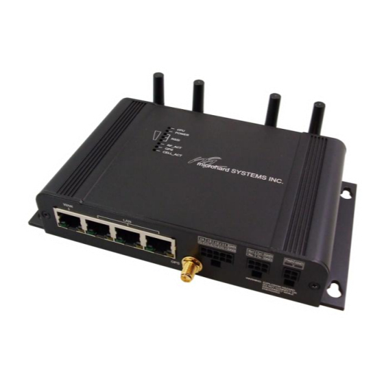
3.0 Hardware Features 3.1.2 Connections 3.1.2.1 Front On the front of the VIP4G Series are, from left to right: Drawing 3-4: VIP4G Front View WAN port 10/100/1000 Ethernet RJ45 Connection. LAN port 3x - 10/100/1000 Ethernet RJ45 Connection. -
Page 23: Rear
3.0 Hardware Features 3.1.2.2 Rear Drawing 3-5: VIP4G Rear View CFG Button Holding this button for 8 seconds while the VIP4G is powered up and running, will cause the unit to reset and load factory default settings: 192.168.168.1 Subnet: 255.255.255.0 Gateway: 192.168.1.1... - Page 24 This slot is used to install a SIM card provided by the cellular carrier to enable communication to their cellular network. Ensure the SIM card is installed properly by paying attention to the diagram printed above the SIM card slot. © Microhard Systems Inc.
-
Page 25: Vip4G Indicators
3.0 Hardware Features 3.1.3 Indicators Drawing 3-6: VIP4G Indicators CPU (Blue) ON indicates the CPU is running. POWER (Red) Illuminates when power is correctly applied to the unit. RSSI (3 LEDs) Indicate the received signal strength of the signal to the Cellular carrier. The number of LED’s illuminated indicate the strength of the signal, with all 3 being illuminated representing a strong signal. -
Page 26: Configuration
VIP4G LAN ETHERNET port to PC NIC card using an Ethernet cable apply power to the VIP4G and wait approximately 60 seconds for the system to load open a web browser and enter the factory default IP address of the unit: 192.168.168.1 ... -
Page 27: Logon Window
4.0 Configuration 4.0.1 Logon Window Upon successfully accessing the VIP4G using a Web Browser, the Logon window will appear. Image 4-2: Logon Window For security, do not allow the web browser to remember the User Name The factory default User Name is: admin or Password. -
Page 28: System
The System Summary screen is displayed immediately after initial login, showing a summary and status of all the functions of the VIP4G in a single display. This information includes System Status, Carrier Status, LAN & WAN network information, version info and WiFi radio status as seen below. -
Page 29: Settings
Options available in the System Settings menu allow for the configuration of the Host Name. Image 4-5: System Settings > System Settings Host Name The Host Name is a convenient identifier for a specific VIP4G Values (characters) unit. This feature is most used when accessing units remotely: The Host Name must not a convenient cross-reference for the unit’s WAN IP address. -
Page 30: Date/Time
4.0 Configuration Time Settings The VIP4G can be set to use a local time source, thus keeping time on its own, or it can be configured to synchronize the date and time via a NTP Server. The options and menus available will change depending on the current setting of the Date and Time Setting Mode, as seen below. -
Page 31: Ntp Server Settings
HTTP Port The secure web port (HTTPS) can be enabled or disabled (port#) Values using the HTTP SSL On/Off drop down menu. If enabled, the port used can be specified, the default is port 443. © Microhard Systems Inc. -
Page 32: Access Control
The default password for ‘admin’ is ‘admin’. admin min 5 characters Confirm Password The exact password must be entered to confirm the password Values (characters) change, if there is a mistake all changes will be discarded. admin min 5 characters © Microhard Systems Inc. -
Page 33: Users
Min 5 characters Max 32 characters Password / Confirm Password Passwords must be a minimum of 5 characters. The Password Values (characters) must be re-entered exactly in the Confirm Password box as (no default) well. min 5 characters © Microhard Systems Inc. -
Page 34: Services
4.1.4 System > Services Available Services Certain services in the VIP4G can be disabled or enabled for either security considerations or resource/power considerations. The Enable/Disable options are applied after a reboot and will take affect after each start up. The Start/Restart/Stop functions only apply to the current session and will not be retained after a power cycle. -
Page 35: Maintenance
Microhard Systems to provide technical support. Image 4-11: Maintenance > Version Information / Firmware Upgrade Firmware Upgrade Occasional firmware updates may be releases by Microhard Systems which include fixes and new features. The firmware can be updated here wirelessly using the WebUI. Erase Current Configuration... -
Page 36: Reset To Default
Image 4-12: Maintenance > Reset to Default / Backup & Restore Configuration Backup & Restore Configuration The configuration of the VIP4G can be backed up to a file at any time using the Backup Configuration feature. The file can the be restored using the Restore Configuration feature. It is always a good idea to backup any configurations in case of unit replacement. -
Page 37: Reboot
The VIP can be remotely rebooted using the System > Reboot menu. As seen below a button ‘OK, reboot now’ is provided. Once pressed, the unit immediately reboots and starts its boot up procedure. Image 4-13: System > Reboot © Microhard Systems Inc. -
Page 38: Logout
4.0 Configuration 4.1.7 System > Logout The logout function allows a user to end the current configuration session and prompt for a login screen. Image 4-14: System > logout © Microhard Systems Inc. -
Page 39: Network
4.2.1 Network > Status The Network Status display gives a overview of the currently configured network interfaces including the Connection Type (Static/DHCP), IP Address, Net Mask, Default Gateway, DNS, and IPv4 Routing Table. Image 4-15: Network > Network Status © Microhard Systems Inc. -
Page 40: Networks
4.0 Configuration 4.2.2 Network > Networks Network Configuration The Networks menu is where the local Ethernet interfaces can be configured. Image 4-16: Network > Network Configuration © Microhard Systems Inc. -
Page 41: Lan Configuration
LAN Configuration The LAN submenu, along with the Wireless Configuration settings, are the minimum required when implementing any VIP4G network. It must be defined if the unit is to be either: assigned an IP address (by a DHCP server), or DHCP: Dynamic Host ... -
Page 42: Wan Configuration
4.0 Configuration Default Gateway If the VIP4G is integrated into a network which has a defined Values (IP Address) gateway, then, as with other hosts on the network, this gateway’s IP address will be entered into this field. If there is a... -
Page 43: Dhcp
4.2.3 Network > DHCP DHCP Configuration > LAN DHCP A VIP4G may be configured to provide dynamic host control protocol (DHCP) service to all attached (either wired or wireless (WiFi)-connected) devices. By default the DHCP service is DHCP: Dynamic Host... -
Page 44: Static Ip Addresses (For Dhcp)
“Remove _______”. Active DHCP Leases This section displays the IP Addresses currently assigned through the DCHP service. Also shown is the MAC Address, Name and Expiry time of the lease for reference. © Microhard Systems Inc. -
Page 45: Vlan
4.2.4 Network > VLAN Network VLAN Configuration The VIP4G has support to participate in VLAN networking, enabling the virtual separation of networks. The VIP4G allows the tagging, un-tagging and filtering of Ethernet frames on the LAN VLAN: Virtual LAN, used & Wireless Ports. - Page 46 VLAN Configuration section below. VLAN1 Configuration VLAN1 is the native VLAN for VIP4G. By default, all traffic will be added to VLAN1 unless specified otherwise by adding additional VLAN(s) for the LAN/Wireless Interfaces. Description Add a name or other description to VLAN1...
-
Page 47: Routes
Image 4-21: Network > Routes Name Routes can be names for easy reference, or to describe the Values (characters) route being added. (no default) Destination Enter the network IP address for the destination. Values (IP Address) (192.168.168.0) © Microhard Systems Inc. -
Page 48: Dynamic Route Configuration
WAN? None Dynamic Route Configuration The VIP4G can support Dynamic Routing on the LAN and Wireless Ports. The VIP4G will communicate with other devices running RIPv2 to automatically populate a routing table. Route Mode Enable /Disable Dynamic Routing. -
Page 49: Gre
4.2.5 Network > GRE GRE Configuration The VIP4G supports GRE (Generic Routing Encapsulation) Tunneling which can encapsulate a wide variety of network layer protocols not supported by traditional VPN. This allows IP packets to travel from one side of a GRE tunnel to the other without being parsed or treated like IP packets. - Page 50 This is the IP Address of the local network. Values (IP Address) (varies) Local WAN IP This is the WAN IP Address of the VIP4G, this field should be Values (IP Address) populated with the current WAN IP address. (varies)
-
Page 51: Snmp
Secure device monitoring over the Internet is possible. In addition to the commands noted as supported above, there is a command to synchronize with a remote management station. The pages that follow describe the different fields required to set up SNMP on the VIP4G. MIBS may be requested from Microhard Systems Inc. - Page 52 SNMP queries. Being part of the community private allows the SNMP agent to process SNMPv1 and SNMPv2c requests. This community name has only READ/WRITE priority. SNMP V3 User Name Defines the user name for SNMPv3. Values (string) V3user © Microhard Systems Inc.
- Page 53 The community name which may receive traps. Values (string) TrapUser Trap Manage Host IP Defines a host IP address where traps will be sent to (e.g. Values (IP Address) SNMP management system PC IP address). 0.0.0.0 © Microhard Systems Inc.
-
Page 54: Sdpserver
Discovery Service Status Use this option to disable or enable the discovery service. Values (selection) Disable / Discoverable / Changable Server Port Settings Specify the port running the discovery service on the VIP4G Values (Port #) unit. 20097 © Microhard Systems Inc. -
Page 55: Carrier
The Carrier Status window provides complete overview information related to the Cellular Carrier portion of the VIP4G. A variety of information can be found here, such as Activity Status, Network (Name of Wireless Carrier connected) , Data Service Type(2G/3G etc), Frequency band, Phone Number etc. -
Page 56: Settings
APN (Access Point Name) The APN is required by every Carrier in order to connect to Values (Selection) their networks. The APN defines the type of network the VIP4G Enable / Disable is connected to and the service type. Most Carrier have more than one APN, usually many, dependant on the types of service offered. - Page 57 Sets the modems connect string if required by the carrier. Not usually Values (string) required in North America. (none) Primary DNS Address If let blank the VIP4G with use the DNS server as specified Values (IP Address) automatically by the service provider. (none) Secondary DNS Address...
- Page 58 IP addresses. Varies by carrier. Password Enter the password for the user name above. May not be Values (characters) required by some carriers, or APN’s Carrier/peer dependant © Microhard Systems Inc.
-
Page 59: Keepalive
The Keep alive tab allows for the configuration of the keep alive features of the VIP4G. The VIP4G can either do a ICMP or HTTP keep alive by attempting to reach a specified address at a regular interval. If the VIP4G cannot reach the intended destination, it will reset the unit in an attempt to obtain a new connection to the carrier. -
Page 60: Traffic Watchdog
Traffic Watchdog Enable or Disable the Traffic Watchdog. Values (Selection) Enable / Disable Check Interval The Check Interval tells the VIP4G how often (in seconds) to Values (seconds) check for wireless traffic to the cellular carrier. (1-60000 seconds) Reboot Time Limit... -
Page 61: Dynamic Dns
Enter a valid password for the user name of the DDNS service Values (characters) selected above. (none) Host This is the host or domain name for the VIP4G as assigned by Values (domain name) the DDNS provider. (none) © Microhard Systems Inc. -
Page 62: Wireless
Traffic Status shows statistics about the transmitted and received data. The VIP4G shows information about all Wireless connections in the Connection Status section. The Wireless MAC address, Noise Floor, Signal to Noise ratio (SNR), Signal Strength (RSSI), The transmit and receive Client Connection Quality (CCQ), TX and RX data rates, and a graphical representation of the signal level or quality. -
Page 63: Radio1
Wireless connections can not be made. The default is On. On / Off Mode The Mode defines which wireless standard to use for the Values (selection) wireless network. The VIP4G supports all 802.11a/b/g/n modes as seen here. Select the appropriate operating 802.11B ONLY 802.11BG mode from the list. -
Page 64: Channel Frequency
WiFi signal needs to travel. The default 10000 is 10km, so the VIP4G will assume that the signal may need to travel up to 10km so it sets various internal timeouts to account for this travel time. Longer distances will require a higher setting, and shorter distances may perform better if the setting is reduced. -
Page 65: Radio Virtual Interface
Image 4-33: Wireless > Radio Configuration Network Choose between LAN or WAN for the Wireless interface. If the Values (selection) unit is configured as a Bridge, only the LAN option will appear in the drop down list. © Microhard Systems Inc. -
Page 66: Operating Mode
24 Mbps (802.11a,g) mcs-8 (14.4/30.0) Mbps 36 Mbps (802.11a,g) mcs-9 (28.9/60.0) Mbps 48 Mbps (802.11a,g) mcs-10 (43.3/90.0) Mbps 54 Mbps (802.11a,g) mcs-11 (57.8/120.0) Mbps mcs-12 (86.7/180.0) Mbps mcs-13 (115.6/240.0) Mbps mcs-14 (130.3/270.0) Mbps mcs-15 (144.4/300.0) Mbps © Microhard Systems Inc. -
Page 67: Tx Power
MESH ID for the Network Name to something unique for your In Mesh Networks, this must be the same for all VIP4G, or VIP Values (string) network. Do this for an Series units participating, similar to the SSID for other wireless... -
Page 68: Encryption Type
Procedure: Input a Key Phrase, select the type of Key to be generated using the Generate Key soft button. Using the same Passphrase on all VIP4G/VIP Series units within the network will generate the same Keys on all units. All units must operate with the same Key selected. -
Page 69: Comport
4.4 Comport 4.4.1 Comport > Status The Status window gives a summary of the Serial port on the VIP4G. The Status window shows if the com port has been enabled, how it is configured (Connect As), and the connection status. -
Page 70: Settings
This menu option is used to configure the serial device server for the serial communications port. Serial device data may be brought into the IP network through TCP, UDP, or multicast; it may also exit the VIP4G network on another VIP Series’ serial port. The fully-featured RS232 interface supports hardware handshaking. -
Page 71: Data Baud Rate
If the attached device does not support hardware handshaking, leave this setting at the default value of ‘None’. When CTS Framing is selected, the VIP4G uses the CTS signal to gate the output data on the serial port. - Page 72 Transparent mode (default), the received data will be output Seamless / Transparent promptly from the VIP4G. When set to Seamless, the serial port server will add a gap between data frames to comply with the MODBUS protocol for example. See ‘Character Timeout’ below for related information.
- Page 73 Values (selection) serial data port when the radio loses synchronization. When Disable / Enable disabled the VIP4G will disregard any data received on the serial data port when radio synchronization is lost. MODBUS TCP Status This option will enable or disable the MODBUS decoding and Values (selection) encoding features.
-
Page 74: Ip Protocol Config
(i.e. no data traffic on the serial port). Default: 60 (seconds) TCP Server: In this mode, the VIP4G Series will not INITIATE a session, rather, it will wait for a TCP: Transmission Client to request a session of it (it’s being the Server—it ‘serves’ a Client). The unit will ‘listen’... -
Page 75: Tcp Client/Server
4.0 Configuration IP Protocol Config (Continued…) TCP Client/Server: In this mode, the VIP4G will be a combined TCP Client and Server, meaning that it can both initiate and serve TCP connection (session) requests. Refer to the TCP Client and TCP Server descriptions and settings described previously as all information, combined, is applicable to this mode. -
Page 76: Udp Point-To-Multipoint (Mp)
-Multipoint (P). Remote IP Address The IP address of a distant device (VIP4G or, for example, a PC) to which the unit In a Point-to-Multipoint sends UDP packets of data received on the serial port. Most often this is the IP (PMP) network topology address of the Access Point. -
Page 77: Smtp Client
4.0 Configuration IP Protocol Config (Continued…) SMTP Client: If the VIP4G has Internet access, this protocol may be used to send the data received on the serial port (COM1), in a selectable format (see Transfer Mode (below)), to an e- mail addressee. -
Page 78: I/O
4.5.1 I/O > Status I/O Status The VIP4G has 4 status inputs, which can be used with various alarms and sensors for monitoring, telling the modem when certain events have occurred, such as an intrusion alarm on a door, a temperature threshold has been exceed, or a generator has failed, out of fuel. Also included are 4 outputs, that can be used to drive external relays to remotely control equipment and devices. - Page 79 4.0 Configuration 4.5 I/O 4.5.2 I/O > OUTPUT OUTPUT Configuration Each of the 4 Outputs can be controlled separately, allowing a user to remotely trigger an event. Image 4-38: I/O > OUTPUT © Microhard Systems Inc.
-
Page 80: Firewall
Firewall Status allows a user to see detailed information about how the firewall is operating. The All, Filter, Nat, Raw, and Mangle options can be used to view different aspects of the firewall. Image 4-39: Firewall > Status © Microhard Systems Inc. -
Page 81: General
“open”. Disable / Enable WAN Remote Management Allow remote management of the VIP4G on the WAN side using the Values WebUI on port 80(HTTP), and 443 (HTTPS). If disabled, the Disable / Enable configuration can only be accessed from the LAN (or 4G if enabled).. -
Page 82: Rules
Rules, MAC, and IP List configuration. 4G to LAN Access Control Allows or Blocks traffic from the 4G accessing the devices on the Values LAN connections unless specified otherwise using the Access Block / Allow Rules, MAC, and IP List configuration. © Microhard Systems Inc. - Page 83 Select the zone which is to be the source of the data traffic. WAN Values applies to the WAN RJ45 connection, and 4G refers to the connection to the cellular carrier. The LAN refers to local connections on the VIP4G (Ethernet/WiFi). None © Microhard Systems Inc.
- Page 84 This field is used to define a port or service used in the rule (i.e. Values (port) Port 80 = HTTP which is generally a web server) Protocol The protocol field defines the transport protocol type controlled by Values the rule. ICMP © Microhard Systems Inc.
-
Page 85: Port Forwarding
Exception Port Enter a exception port number that will NOT be forwarded to the Values (Port #) DMZ server IP. Usually a configuration or remote management port that is excluded to retain external control of the VIP4G. © Microhard Systems Inc. - Page 86 4G / WAN Internal Server IP Enter the IP address of the intended internal (i.e. on LAN side of Values (IP Address) VIP4G) server. This is the IP address of the device you are 192.168.2.1 forwarding traffic to. Internal Port Target port number of internal server on the LAN IP entered above.
-
Page 87: Mac-Ip List
MAC List configuration can be used to control which physical LAN devices can access the ports on the VIP4G, by restricting or allowing connections based on the MAC address. IP List configuration can be used to define who or what can access the VIP4G, by restricting or allowing connections based on the IP Address/Subnet. -
Page 88: Ip List Configuration
192.168.0.0/24 will apply to all IP addresses in the 0.0.0.0/0 192.168.0.1 - 192.168.0.254 range (subnet /24 = 255.255.255.0). Destination Address Optional, enter a destination IP address to make the IP list more Values (IP Address) specific. Leave as 0.0.0.0/0 to not use. 0.0.0.0/0 © Microhard Systems Inc. -
Page 89: Multicast
4.0 Configuration 4.7 Multicast Multicast Configuration Multicast can be enabled or disabled for the VIP4G. This section allows for the configuration of the Multicast feature. Image 4-44: Multicast Mode Enable or Disable Multicast in the VIP4G Values (selection) Disable / Enable Rate Use the drop down selection to chose the Multicast rate. - Page 90 Local LAN IP Address of the VIP4G interface connected to the Values (IP Address) Multicast Device/Source. 192.168.2.1 Remote IP IP Address of the remote LAN IP of the VIP4G/VIP Series in which Values (IP Address) to send the multicast data. 192.168.5.1 Source IP IP Address of the Multicast PC/Device.
-
Page 91: Qos
4.0 Configuration 4.8 QoS 4.8.1 QoS > Status QoS Status gives a visual overview of the QoS configuration as seen below. Image 4-45: QoS > Status © Microhard Systems Inc. -
Page 92: Class
Image 4-46: QoS > Class QoS Mode Use this option to enable or disable the QoS features of the VIP4G. Values (selection) By default QoS is not enabled. -
Page 93: Local
Target Select the target class for the QoS rule, the class specifics can be Values (selection) modified in the Class menu. High Medium_high Medium Medium_low Source IP Enter the source IP. Values (IP Address) (IP Address) © Microhard Systems Inc. - Page 94 (IP Address) Protocol Select the protocol type, TCP, UDP or ICMP. Values (selection) ICMP Destination Port Enter the port number for the destination. Values (port#) port # Ports Enter the port number. Values (port#) port # © Microhard Systems Inc.
-
Page 95: Interface
Values (selection) Enable / Disable Target Select the target class for the QoS rule, the class specifics can be Values (selection) modified in the Class menu. High Medium_high Medium Medium_low Bandwidth Enter the Bandwidth. Values (Mbit) © Microhard Systems Inc. -
Page 96: Vpn
4.9 VPN 4.9.1 VPN > Summary A Virtual Private Network (VPN) may be configured to enable a tunnel between the VIP4G and a remote network.. The VIP4G supports VPN IPsec Gateway to Gateway (site-to-site) tunneling, meaning you are using the VIP4G to connect a tunnel to network with VPN capabilities. The IPn3G can also operate as a L2TP Server, allowing users to VPN into the unit from a remote PC, and a L2TP Client. -
Page 97: Gateway To Gateway
Enter a name for the VPN Tunnel. Up to 16 different tunnels can be Values (chars) created, each requiring a unique name. tunnel1 Enable Used to enable (checked) is disable (unchecked) the VPN tunnel. Values (checkbox) Enable (Checked) © Microhard Systems Inc. - Page 98 4.0 Configuration Local Group Setup Gateway IP Address Displays the IP address of the VIP4G, which is the local VPN Values (IP Address) Gateway. Current IP Address Subnet IP Address Define the local network by specifying the local subnet. Values (IP Address) Subnet Mask Specify the subnet mask of the local network address.
- Page 99 Select value to match the values required by the remote VPN router. Values (selection) modp1024 modp1536 modp2048 Phase 2 Encryption Select value to match the Phase 1 Encryption type used by the remote Values (selection) VPN router. 3des aes128 aes256 © Microhard Systems Inc.
- Page 100 Dead Peer Detection is used to detect if there is a dead peer. Set the DPD Values (seconds) Delay (seconds), as required. DPD Timeout(s) Set the DPD (Dead Peer Detection) Timeout (seconds), as required. Values (seconds) DPD Action Set the DPD action, hold or clear, as required. Values (seconds) Hold Clear © Microhard Systems Inc.
-
Page 101: Client To Gateway (L2Tp Client)
4.0 Configuration 4.9.3 VPN > Client To Gateway (L2TP Client) The VIP4G can operate as a L2TP Client, allowing a VPN connection to be made with a L2TP Server. Image 4-51: VPN > Client to Gateway Tunnel Name Enter a name for the VPN Tunnel. Up to 16 different tunnels can be Values (chars) created, each requiring a unique name. - Page 102 The default is 0, which means the time is infinite. (0—65535) Username Enter the Username Values (chars) Preshared Key The preshared key is required to connect to the L2TP Server. Values (chars) IPSec Setup - See previous sections for additional info. © Microhard Systems Inc.
-
Page 103: L2Tp Server
Current IP Address IP Address Range Start - IP Address Range End Define the range of IP addresses that can be assigned by the L2TP Server. Values (IP Address) IPSec Setup - See previous sections for additional info. © Microhard Systems Inc. -
Page 104: Vpn Client Access
Enter a username for the user being set up. Values (characters) New Password Enter a password for the use. Values (characters) Confirm New Password Enter the password again, the VIP4G will ensure that the password match. Values (IP Address) © Microhard Systems Inc. -
Page 105: Tools
4.10.1 Tools > Discovery Network Discovery The Network discovery tool allows the VIP4G to send a broadcast to all VIP4G/VIP Series units on the same network. Other units on the network will respond to the broadcast and report their MAC address, IP address (With a hyperlink to that units WebUI page), description, firmware version, operating mode, and the SSID (regardless of whether it was set to broadcast or not). -
Page 106: Site Survey
The Wireless Survey feature will scan the available wireless channels for any other 802.11 wireless networks in proximity to the VIP4G. The Survey will display the Channel number the other networks are operating on, the MAC address, Encryption Type, Frequency and general signal level and quality information. -
Page 107: Ping
The Network Tools Ping feature provides a tool to test network connectivity from within the VIP4G unit. A user can use the Ping command by entering the IP address or host name of a destination device in the Ping Host Name field, use Count for the number of ping messages to send, and the Packet Size to modify the size of the packets sent. -
Page 108: Traceroute
Network TraceRoute The Trace Route command can be used to provide connectivity data by providing information about the number of hops, routers and the path taken to reach a particular destination. Image 4-57: Tools > TraceRoute © Microhard Systems Inc. -
Page 109: Network Traffic
4.10.5 Tools > Network Traffic Network Traffic Monitor Tool The Tools > Network Traffic tab displays a graphical display of all data Traffic on the VIP4G. br-lan Shows an overview of all data sent or received by the VIP4G. A summary of the data of the current day and the current month is shown. -
Page 110: Appendices
(DCE); the module transmits data on the RX line, and receives on TX. “DCE” and “module” are often synonymous since a module is typically a DCE device. “DTE” is, in most applications, a device such as a host PC. © Microhard Systems Inc. -
Page 111: Appendix C: Firmware Recovery
Ø Change transfer protocol to *BINARY* mode; Ø Push package upgrade file into the system with “put” command; Ø Package upgrade takes more than 2 minutes to complete. Ø The unit automatically reboots after the recovery procedure is completed © Microhard Systems Inc. - Page 112 150 Country Hills Landing NW Calgary, Alberta Canada T3K 5P3 Phone: (403) 248-0028 Fax: (403) 248-2762 www.microhardcorp.com © Microhard Systems Inc.
Need help?
Do you have a question about the VIP4G and is the answer not in the manual?
Questions and answers