Table of Contents
Advertisement
Quick Links
Advertisement
Table of Contents

Related Manuals for Microhard Systems VIP4G


Summary of Contents for Microhard Systems VIP4G
- Page 1 Operating Manual VIP4G / VIP4Gb LTE Ethernet Bridge/Serial Gateway Document: VIP4G Operating Manual.v1.6.pdf FW Version: 1.1.6-r1190-4 December 2015 150 Country Hills Landing NW Calgary, Alberta Canada T3K 5P3 Phone: (403) 248-0028 Fax: (403) 248-2762 www.microhardcorp.com...
- Page 2 Important User Information Warranty Microhard Systems Inc. warrants that each product will be free of defects in material and workmanship for a period of one (1) year for its products. The warranty commences on the date the product is shipped by Micro- hard Systems Inc.
- Page 3 Highlights a key feature, point, or step which is noteworthy. Keeping these in mind will simplify or enhance device usage. An idea or suggestion to improve efficiency or enhance usefulness. Information Information regarding a particular technology or concept. © Microhard Systems Inc.
- Page 4 Please Note: These are only sample labels; different products contain different identifiers. The actual identifiers should be seen on your devices if applicable. S'il vous plaît noter: Ce sont des exemples d'étiquettes seulement; différents produits contiennent des identifiants différents. Les identifiants réels devrait être vu sur vos périphériques le cas échéant. © Microhard Systems Inc.
- Page 5 Microhard Systems Inc. and a Class 1 Division 2 power source within your panel. If you are unsure as to the specific wiring and installation guidelines for Class 1 Division 2 codes, contact CSA International.
-
Page 6: Microhard Systems Inc
Updated to firmware version v1.1.6-r1190-4. Added Router menu. Updated AT Commands, Up- Dec 2015 dated AT commands, Removed Mesh, Updated System, Updated Network, Updated Carrier, Up- dated Wireless, Updated Tools, Updated Screenshots. Misc Corrections & Formatting. © Microhard Systems Inc. -
Page 7: Table Of Contents
2.3.1 Setting up WiFi ........................ 17 2.3.1 Connecting to WiFi ......................18 3.0 Hardware Features ..................VIP4G ............................20 3.1.1 VIP4G Mechanical Drawings .................... 21 3.1.2 VIP4G Connections ......................22 3.1.2.1 Front ........................22 3.1.2.2 Rear ........................23 3.1.3 VIP4G Indicators ......................25 4.0 Configuration.................... - Page 8 4.6.4 Accelerometer ......................... 106 4.7 GPS ..........................108 4.7.1 Location .......................... 108 4.7.2 Settings ........................... 109 4.7.3 GPS Report ........................110 4.7.4 GpsGate ......................... 112 4.7.5 Recorder ......................... 115 4.7.6 Load Record........................117 4.7.7 TAIP..........................119 © Microhard Systems Inc.
- Page 9 Appendix C: Port Forwarding Example ....................194 Appendix D: Firewall Example ......................196 Appendix E: VPN Example ........................ 198 Appendix F: GRE Example ......................... 200 Appendix G: Firmware Recovery Procedure ..................203 Appendix H: Troubleshooting (FAQ) ....................204 © Microhard Systems Inc.
-
Page 10: Overview
1.0 Overview The VIP4G is a high-performance 4G LTE Cellular Ethernet & Serial Gateway with 802.11 a/ b/g/n WiFi capability, 4 Gigabit Ethernet Ports, 4x Digital I/O, and a fully complimented RS232/485/422 serial port. The VIP4G utilizes the cellular infrastructure to provide network access to wired and wireless devices anywhere cellular coverage is supported by a cellular carrier. -
Page 11: Specifications
Serial Baud Rate: 300bps to 921kbps Ethernet: 10/100/1000 BaseT, Auto - MDI/X, IEEE 802.3 Network Protocols: TCP, UDP, TCP/IP, TFTP, ARP, ICMP, DHCP, HTTP, HTTPS*, SSH*, SNMP, FTP, DNS, Serial over IP Operating Modes: Access Point, Client/Station, Repeater © Microhard Systems Inc. - Page 12 Mating Connector: 4-Pin Micro MATE-N-LOK AMP 794617-4 Misc: Digital I/O: SMT: 10-Pin Micro MATE-N-LOK AMP 4-794618-0 Mating Connector: 10-Pin Micro MATE-N-LOK AMP 1-794617-0 IP67 Enclosure (Optional): Approx: 8.4”(213mm) X 7.2”(182mm) X 1.75” (44mm) Dimensions: Weight: Approx: 1.25 kg © Microhard Systems Inc.
-
Page 13: Quick Start
VIP4G unit. Installing the SIM Card Before the VIP4G can be used on a cellular network a valid SIM Card for your Wireless Carrier must be installed. Insert the SIM Card into the slot as shown below. SIM Card Slot... - Page 14 Connect A PC configured for DHCP directly to one of the LAN ETHERNET ports of the VIP4G, using an Ethernet Cable. If the PC is configured for DHCP it will acquire a IP Ad- dress from the VIP4G. ...
- Page 15 Carrier > Settings tab and enter the APN supplied by your carrier in the APN field. Auto APN: Introduced in Some carriers may also require a Username and Password. firmware version v1.1.6- r1142, the VIP4G will attempt to detect the carrier based on the SIM card installed and cycle through a list of commonly used APN’s to...
- Page 16 Ensure the default passwords are changed. To access devices connected to VIP4G remotely, one or more of the following must be configured: IP-Passthrough, Port Forwarding, DMZ. Another option would be to set up a VPN. Ensure that all default passwords are changed to limit access to the mo- dem.
-
Page 17: Getting Started With Wifi
figure the Carrier in a VIP4G. Click on the Wireless > Radio1 Tab to setup the WiFi portion of the VIP4G. In Radio1 Phy Configuration, ensure the mode is set for 802.11NG. In the Radio1 Virtual Interface, en- sure that the Mode is set for Access Point. -
Page 18: Connecting To Wifi
2.0 Quick Start 2.3.2 Connecting to WiFi Now that the VIP4G has connection to the Cellular Carrier (See Section 2.2) and the WiFI has been set up (See Section 2.3), WiFi devices should be able to detect and connect to the VIP4G. - Page 19 2.0 Quick Start The status of the WiFi connection should also be visible in the Wireless > Status tab in the WebUI as seen below. © Microhard Systems Inc.
-
Page 20: Hardware Features
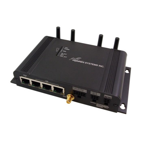
3.0 Hardware Features 3.1 VIP4G The VIP4G is a fully-enclosed unit ready to be interfaced to external devices. Image 3-1: Front View of VIP4G Image 3-2: Rear View of VIP4G VIP4G Hardware Features Include: Standard Connectors for: 1 WAN Ethernet Ports (RJ45) ... -
Page 21: Vip4G Mechanical Drawings
3.0 Hardware Features 3.1.1 Mechanical Drawings Drawing 3-1: VIP Top View Dimensions Drawing 3-2: VIP Front View Dimensions Drawing 3-3: VIP Rear View Dimensions Note: All dimension units: Millimeter & Inches (mm/inches) © Microhard Systems Inc. -
Page 22: Vip4G Connections
3.0 Hardware Features 3.1.2 Connections 3.1.2.1 Front On the front of the VIP4G Series are, from left to right: Drawing 3-4: VIP4G Front View WAN port 10/100/1000 Ethernet RJ45 Connection. 802.3af Passive PoE (WAN port only) Ethernet RJ45 Connector Pin Number... -
Page 23: Rear
3.0 Hardware Features 3.1.2.2 Rear Drawing 3-5: VIP4G Rear View CFG Button Holding this button for 8 seconds while the VIP4G is powered up and running, will cause the unit to reset and load factory default settings: 192.168.168.1 Subnet: 255.255.255.0 With these settings a web browser can be used to configure the unit. - Page 24 This slot is used to install a SIM card provided by the cellular carrier to enable communication to their cellular network. Ensure the SIM card is installed properly by paying attention to the diagram printed above the SIM card slot. © Microhard Systems Inc.
-
Page 25: Vip4G Indicators
3.0 Hardware Features 3.1.3 Indicators Drawing 3-6: VIP4G Indicators CPU (Blue) ON indicates the CPU is running. POWER (Red) Illuminates when power is correctly applied to the unit. RSSI (3 LEDs) Indicate the received signal strength of the signal to the Cellular carrier. The number of LED’s illuminated indicate the strength of the signal, with all 3 being illuminated representing a strong signal. -
Page 26: Configuration
4.0 Configuration 4.0 Web User Interface Image 4-0-1: WebUI Initial configuration of an VIP4G using the Web User (Browser) Interface (Web UI) method involves the following steps: configure a static IP Address on your PC to 192.168.168.10 (or any address on the 192.168.168.X subnet other than the default IP of 192.168.168.1) -
Page 27: Logon Window
4.0 Configuration 4.0.1 Logon Window Upon successfully accessing the VIP4G using a Web Browser, the Logon window will appear. Image 4-0-2: Logon Window For security, do not allow the The factory default User Name is: admin web browser to remember the User Name or Password. -
Page 28: System
4.0 Configuration 4.1 System The main category tabs located at the top of the navigation bar separate the configuration of the VIP4G into different groups based on function. The System Tab contains the following sub menu’s: Summary Status summary of entire radio including network settings, version information, and radio connection status. -
Page 29: Settings
Host Name wireless device within a VIP4G network. The Host Name is a convenient identifier for a specific VIP4G unit. Values (characters) This feature is most used when accessing units remotely: a convenient cross-reference for the unit’s WAN IP address. This name appears... -
Page 30: Syslog
Enter the UDP port number on the Syslog Server where the actual Values (UDP Port #) service is running. Consult with the documentation of your chosen Syslog Server for the correct port number. The most common port is 514, which has been set as the default. © Microhard Systems Inc. -
Page 31: Date/Time
Time Settings The VIP4G can be set to use a local time source, thus keeping time on its own, or it can be configured to synchronize the date and time via a NTP Server. The options and menus available will change depending on the current setting of the Date and Time Setting Mode, as seen below. -
Page 32: Http Port Settings
The default web server port for the web based configuration tools used (port#) Values in the VIP4G is port 80. If a non standard port is used, it must be specified in a internet browser to access the unit. (example: http://192.168.168.1:8080) -
Page 33: Access Control
The default password for ‘admin’ is ‘admin’. admin min 5 characters Confirm Password The exact password must be entered to confirm the password change, Values (characters) if there is a mistake all changes will be discarded. admin min 5 characters © Microhard Systems Inc. -
Page 34: Users
Min 5 characters Max 32 characters Password / Confirm Password Passwords must be a minimum of 5 characters. The Password must Values (characters) be re-entered exactly in the Confirm Password box as well. (no default) min 5 characters © Microhard Systems Inc. -
Page 35: Services
4.1.4 System > Services Available Services Certain services in the VIP4G can be disabled or enabled for either security considerations or resource/ power considerations. The Enable/Disable options are applied after a reboot and will take affect after each start up. The Start/Restart/Stop functions only apply to the current session and will not be retained after a power cycle. -
Page 36: Telnet
FTP Server Using the FTP Service Enable/Disable function, you can disable the Values (selection) FTP service (Port 21) from running on the VIP4G. This port is reserved for internal use / future use. Start / Restart / Stop Microhard Sh Custom SSH Port. -
Page 37: Power Saving
5 minutes before power saving will work. The VIP4G requires that the IGN line be ON (1.8 - 32V) to boot up and perform normal operations. If the IGN line goes OFF (Less than 1.8V) or floating (The Ignition of the vehicle turned OFF), the VIP4G will then look at the Power Down Delay and start counting down to when it will turn itself off. -
Page 38: Maintenance
Microhard Systems to provide technical support. Image 4-1-9: Maintenance > Version Information / Firmware Upgrade Firmware Upgrade Occasional firmware updates may be releases by Microhard Systems which include fixes and new features. The firmware can be updated here wirelessly using the WebUI. Erase Current Configuration... -
Page 39: Reset To Default
4.0 Configuration 4.1.6 System > Maintenance Reset to Default The VIP4G may be set back to factory defaults by using the Reset to Default option under System > Maintenance > Reset to Default. *Caution* - All settings will be lost!!! Image 4-1-10: Maintenance >... -
Page 40: Reboot
4.0 Configuration 4.1.7 System > Reboot The VIP4G can be remotely rebooted using the System > Reboot menu. As seen below a button ‘OK, reboot now’ is provided. Once pressed, the unit immediately reboots and starts its boot up procedure. -
Page 41: Network
4.2.1 Network > Status The Network Status display gives a overview of the currently configured network interfaces including the Connection Type (Static/DHCP), IP Address, Net Mask, Default Gateway, DNS, and IPv4 Routing Table. Image 4-2-1: Network > Network Status © Microhard Systems Inc. -
Page 42: Lan
Network LAN Configuration The Ethernet port (RJ45) on the back of the VIP4G is the LAN port, used for connection of devices on a local network. By default, this port has a static IP Address of 192.168.168.1. It also, by default is running a DHCP server to provide IP Addresses to devices that are connected to the physical port, and devices connected by a WiFi connection (if equipped). - Page 43 IP address. Connection Type This selection determines if the VIP4G will obtain an IP address from a Values (selection) DHCP server on the attached network, or if a static IP address will be entered. If a Static IP Address is chosen, the fields that follow must DHCP also be populated.
- Page 44 4.0 Configuration LAN DHCP A VIP4G may be configured to provide dynamic host control protocol (DHCP) service to all attached (either wired or wireless (WiFi)-connected) devices. By default the DHCP service is enabled, so devices that are connected to the physical Ethernet LAN ports, as well as any devices that are connected by WiFi will be assigned an IP by the VIP4G.
- Page 45 (no default) WINS/NBT Node Type Select the method used to resolve computer names to IP addresses. Values (selection) Four name resolution methods are available: B-node: broadcast none P-node: point-to-point b-node M-node: mixed/modified p-node H-node: hybrid m-node h-node © Microhard Systems Inc.
- Page 46 MAC Address, Name and Expiry time of the lease for reference. Network Interfaces When additional Network Interfaces are added, they will show up here in a list. You can remove Network Interfaces by clicking “Remove _______”. © Microhard Systems Inc.
-
Page 47: Wan
4.2.3 Network > WAN WAN Configuration The WAN configuration refers to the wired WAN connection on the VIP4G. The WAN port can be used to connect the VIP4G to other networks, the internet and/or other network resources. Image 4-2-6: Network > WAN Configuration Working Mode Use this to set the function of the physical WAN RJ45 port. - Page 48 4.0 Configuration Default Gateway If the VIP4G is integrated into a network which has a defined gateway, Values (IP Address) then, as with other hosts on the network, this gateway’s IP address will be entered into this field. If there is a DHCP server on the network,...
-
Page 49: Wifi
DHCP services to connecting devices. In most cases the WIFI interface would be setup to allow the VIP4G to operate as a Client to another Access Point (AP). Using this menu it can be decided to use DHCP to obtain an IP address and related networking information from the connected Access Point, or it could be setup with a static IP address that is part of the AP’s network. -
Page 50: Switch
4.0 Configuration 4.2.5 Network > Switch The VIP4G has the capability to add multiple network interfaces. It may also be desirable to segment these different subnets. The VIP4G features two different VLAN mode, Port Based, and 802.1Q VLAN. In port based VLAN port membership is exclusive, a port can only belong to a single VLAN, and is generally used to separate the different subnets. - Page 51 It is important for switch-to-switch connections to use a consistent Native VLAN. VLAN Mode By default the VIP4G is configured to Port Based VLAN with all ports Values (selection) bridged. See above description for differences between Port Based and Tagged VLANs.
-
Page 52: Routes
It may be desirable to have devices on different subnets to be able to talk to one another. This can be accomplished by specifying a static route, telling the VIP4G where to send data. The modem must be restarted before new routes will take effect. - Page 53 The more hops it takes to get to a destination, the higher the metric. Interface Define the exit interface. Is the destination a device on the LAN, or the Values (Selection) WAN? None © Microhard Systems Inc.
-
Page 54: Gre
4.2.7 Network > GRE GRE Configuration The VIP4G supports GRE (Generic Routing Encapsulation) Tunneling which can encapsulate a wide variety of network layer protocols not supported by traditional VPN. This allows IP packets to travel from one side of a GRE tunnel to the other without being parsed or treated like IP packets. - Page 55 The local setup refers to the local side of the GRE tunnel, as opposed to the remote end. Gateway IP Address This is the WAN IP Address of the VIP4G, this field should be populated Values (IP Address) with the current WAN IP address.
- Page 56 Values (IP Address) (varies) Remote Setup The remote setup tells the VIP4G about the remote end, the IP address to create the tunnel to, and the subnet that is accessible on the remote side of the tunnel. Gateway IP Address...
-
Page 57: Pim-Sm
4.2.8 Network > PIM-SM PIM-SM Configuration The VIP4G can be set up with Protocol Independent Multicast - Sparse Mode (PIM-SM) which is a multicast routing protocol developed by Cisco Systems. This menu allows the configuration of the VIP4G to perform as a multicast router, which when enabled can transport multicast data streams to/from other multicast routers or to/from source/clients. - Page 58 Image 4-2-13: Network > PIM-SM Configuration RP Point IP If the static RP is a unicast address, enter that address here. Values (none) Group IP Enter the optional multicast group IP here for the RP. Values (none) © Microhard Systems Inc.
- Page 59 Mask Length The number of IP address segments taken up by the netmask. Values Remember that a multicast address is a Class D and has a netmask of 240.0.0.0, which means its length is 4. (none) © Microhard Systems Inc.
- Page 60 Switch Register Threshold Rate Switch Register Threshold does the opposite of the Switch Data Values (bps) Threshold Rate in the same format. (none) Switch Register Threshold Interval Sample rate in seconds (recommended minimum of 5 seconds) Values (seconds) (none) © Microhard Systems Inc.
-
Page 61: Snmp
Internet is possible. In addition to the commands noted as supported above, there is a command to synchronize with a remote management station. The pages that follow describe the different fields required to set up SNMP on the VIP4G. MIBS may be requested from Microhard Systems Inc. - Page 62 SNMP queries. Being part of the community allows the SNMP agent to process SNMPv1 and SNMPv2c requests. This community name has private only READ/WRITE priority. SNMP V3 User Name Defines the user name for SNMPv3. Values (string) V3user © Microhard Systems Inc.
- Page 63 The community name which may receive traps. Values (string) TrapUser Trap Manage Host IP Defines a host IP address where traps will be sent to (e.g. SNMP Values (IP Address) management system PC IP address). 0.0.0.0 © Microhard Systems Inc.
-
Page 64: Sdpserver
Discovery Service Status Use this option to disable or enable the discovery service. Values (selection) Disable / Discoverable / Changable Server Port Settings Specify the port running the discovery service on the VIP4G unit. Values (Port #) 20097 © Microhard Systems Inc. -
Page 65: Local Monitor
The Local Device Monitor allows the VIP4G to monitor a local device connected locally to the Ethernet port or to the locally attached network. If the VIP4G cannot detect the specified IP or a DHCP assigned IP, the unit will restart the DHCP service, and eventually restart the modem to attempt to recover the connection. -
Page 66: Carrier
The Carrier Status window provides complete overview information related to the Cellular Carrier portion of the VIP4G. A variety of information can be found here, such as Activity Status, Network (Name of Wireless Carrier connected) , Data Service Type WCDMA/HSPA/HSPA+/LTE etc), Frequency band, Phone Number etc. -
Page 67: Settings
Roaming is Disabled by default. Disable Carrier. In some cases this could be an excessive, and unexpected amount. It is important to understand the data plan with the Cellular Carrier. © Microhard Systems Inc. -
Page 68: Ip-Passthrough
System > Settings Menu. The SNMP Listening Port (Default Port: UDP 161). Local WebUI of the VIP4G is retained by using the first 3 octets of the Wan IP and changing the last octet to 1. IP-Passthrough Mode... -
Page 69: Apn (Access Point Name)
Sets the modems connect string if required by the carrier. Not usually Values (string) required in North America. (none) Primary DNS Address If let blank the VIP4G with use the DNS server as specified Values (IP Address) automatically by the service provider. (none) Secondary DNS Address... - Page 70 IP Carrier/peer dependant addresses. Varies by carrier. Password Enter the password for the user name above. May not be required by Values (characters) some carriers, or APN’s Carrier/peer dependant © Microhard Systems Inc.
-
Page 71: Keepalive
The Keepalive ensures that there is internet/network connectivity to the address specified at all times. If the VIP4G does not have a SIM card installed, is not connected to the Carrier, or is on a private APN, the default keepalive may not work and the unit will reboot at the interval configured. -
Page 72: Traffic Watchdog
Enable or Disable the Traffic Watchdog. Values (Selection) Enable / Disable Check Interval The Check Interval tells the VIP4G how often (in seconds) to check for Values (seconds) wireless traffic to the cellular carrier. (1-60000 seconds) Reboot Time Limit The Reboot Timer will reset the unit if there has been no Cellular RF Values (seconds) activity in the configured time. -
Page 73: Dynamic Dns
Enter a valid password for the user name of the DDNS service Values (characters) selected above. (none) Host This is the host or domain name for the VIP4G as assigned by the Values (domain name) DDNS provider. (none) © Microhard Systems Inc. -
Page 74: Sms Config
4.3.6 Carrier > SMS Config SMS messages can be used to remotely reboot or trigger events in the VIP4G. SMS alerts can be set up to get SMS messages based on system events such as Roaming status, RSSI, Ethernet Link Status or IO Status. -
Page 75: System Sms Alerts
SMS alerts, when active, will be sent out at the frequency defined Values (Seconds) here. Device Alias The Device Alias allows you to add a useful, recognizable name or Values (chars) other text characters with each SMS notifcation (varies) © Microhard Systems Inc. - Page 76 Disable Roaming Check Enable Roaming Check Home / Roaming Status The VIP4G can send alerts based on the roaming status. Data rates Values (Selection) during roaming can be expensive and it is important to know when a device has started roaming.
-
Page 77: Sms
4.0 Configuration 4.3.7 Carrier > SMS SMS Command History The SMS menu allows a user to view the SMS Command History and view the SMS messages on the SIM Card. Image 4-3-8: SMS > SMS Command History © Microhard Systems Inc. -
Page 78: Data Usage Alerts
4.3.8 Carrier > Data Usage The Data Usage tool on the VIP4G allows users to monitor the amount of cellular data consumed. Since cellular devices are generally billed based on the amount of data used, alerts can be triggered by setting daily and/or monthly limits. - Page 79 Period Start Day For Monthly tracking, select the day the billing/data cycles begins. On this Values (1-31) day each month the VIP4G will reset the data usage monitor numbers. 1 (Day of Month) Phone Number If SMS is selected as the notification method, enter the phone number to...
- Page 80 Port settings above reflect the correct settings. Contact your provider for None this information if it is not known. SSL/TLS STARTTLS SSL/TLS + STARTTTLS Mail Recipient Enter the email address of the individual or distribution list to send the Values (xx@xx.xx) email notification to. host@ © Microhard Systems Inc.
-
Page 81: Wireless
Traffic Status shows statistics about the transmitted and received data. The VIP4G shows information about all Wireless connections in the Connection Status section. The Wireless MAC address, Noise Floor, Signal to Noise ratio (SNR), Signal Strength (RSSI), The transmit and receive Client Connection Quality (CCQ), TX and RX data rates, and a graphical representation of the signal level or quality. -
Page 82: Radio1
On / Off Mode The Mode defines which wireless standard to use for the wireless Values (selection) network. The VIP4G supports all 802.11a/b/g/n modes as seen here. Select the appropriate operating mode from the list. 802.11B ONLY 802.11BG The options below are dependant and vary on the operating mode 802.11NG-High Throughout 2.4GHz... -
Page 83: Channel Frequency
Values (meters) distance the WiFi signal needs to travel. The default is 10km, so the VIP4G will assume that the signal may need to travel up to 10km so it 10000 sets various internal timeouts to account for this travel time. Longer distances will require a higher setting, and shorter distances may perform better if the setting is reduced. -
Page 84: Radio Virtual Interface
The bottom section of the Wireless Configuration provides for the configuration of the Operating Mode of the Wireless Interface, the TX power, Wireless Network information, and Wireless Encryption. The VIP4G can support multiple virtual interfaces. These interfaces provide different SSID’s for different users, and can also be assigned to separate subnets (Network Interfaces) to prevent groups from interacting. -
Page 85: Operating Mode
Client If more than 1 Virtual Interface (more than 1 SSID) has been defined, Repeater the VIP4G can ONLY operate as a Access Point, and will be locked into this mode. Station/Client - A Station may sustain one wireless connection, i.e. to an Access Point. -
Page 86: Tx Power
Values (selection) will not be able to communicate with each other. In other words if the VIP4G is being used as a Hot Spot for many wireless clients, AP On / Off Isolation would provide security for those clients by not allowing access to any other wireless device. -
Page 87: Encryption Type
The MAC filter allows the control of which WIFI devices can, or cannot Values (selection) connect to the VIP4G. If set to Allow, only the MAC Addresses listed will be allowed to connect, all others will be blocked. When set to Disabled / Allow / Deny Deny, only the devices (via MAC) will be blocked. -
Page 88: Hotspot
This is a secret password between the Redirect URL and the Hotspot Values given by the hotspot provider. hotsys123 UAM Allowed UAM Allowed is a list of websites that unauthenticated users are Values allowed to access. (varies) © Microhard Systems Inc. - Page 89 Hotspot will assign the IP addresses to the connected devices, select the starting range here. DHCP End When devices connect to the BulletPlus WiFi and Hotspot is enabled, Values the Hotspot will assign the IP addresses to the connected devices, select the ending range here. © Microhard Systems Inc.
- Page 90 The Radius Account Port Number. The default is 1813. This is Values provided by your Hotspot service provider. 1813 Radius Secret Also called a shared key, this is the RADIUS password assigned by Values you Hotspot provider. hotsys123 © Microhard Systems Inc.
- Page 91 4.0 Configuration Radius CoA UDP Port Specify the Radius CoA UDP Port here. This information is supplied by Values (port) the hotspot service provider. 3799 © Microhard Systems Inc.
-
Page 92: Netmotion
When Netmotion is enabled, the Wireless interface cannot be used as a Access Point for other devices to connect to. Image 4-4-6: Wireless > Netmotion Disable/Enable Use this option to enable or disable the Netmotion functionality of the Values (selection) modem. Enable / Disable © Microhard Systems Inc. -
Page 93: Roam
This is ideal for mobile applications, where the modem will be moving from place to place. Unwanted networks can be removed from the history list to prevent the modem from using it. Image 4-4-7: Wireless > Roam © Microhard Systems Inc. -
Page 94: Comport
4.5 Comport 4.5.1 Comport > Status The Status window gives a summary of the Serial port on the VIP4G. The Status window shows if the com port has been enabled, how it is configured (Connect As), and the connection status. -
Page 95: Settings
This menu option is used to configure the serial device server for the serial communications port. Serial device data may be brought into the IP network through TCP, UDP, or multicast; it may also exit the VIP4G network on another VIP4G serial port. The fully-featured RS232 interface supports hardware handshaking. -
Page 96: Data Baud Rate
If the attached device does not support hardware handshaking, leave this setting at the default value of ‘None’. When CTS Framing is selected, the VIP4G uses the CTS signal to gate the output data on the serial port. - Page 97 Timeout criteria has been met, or the buffer is full, it packetizes the 1024 received frame and transmits it. Priority This setting effects the quality of service associated with the data Values (selection) traffic on the COM port. Normal / Medium / High © Microhard Systems Inc.
- Page 98 When enabled the data will continue to buffer received on the serial Values (selection) data port when the radio loses synchronization. When disabled the VIP4G will disregard any data received on the serial data port when Disable / Enable radio synchronization is lost.
-
Page 99: Ip Protocol Config
Default: 60 (seconds) TCP Server: In this mode, the VIP4G Series will not INITIATE a session, rather, it will wait for a Client to request a session of it (it’s being the Server—it ‘serves’ a Client). The unit will ‘listen’ on a specific TCP port. -
Page 100: Tcp Client/Server
Default: 20001 SMTP Client: If the VIP4G has Internet access, this protocol may be used to send the data received on the serial port (COM1), in a selectable format (see Transfer Mode (below)), to an e-mail addressee. Both the SMTP Server and the e-mail addressee must be ‘reachable’... -
Page 101: Sms Transparent Mode
SMS Transparent Mode: Serial data from the COM1 port can be send to one or multiple destinations via SMS text messaging. SMS messages received by the VIP4G can also be sent to the COM1 port. Image 4-5-3: Comport > SMS Transparent Mode ... -
Page 102: Gps Transparent Mode
IP Protocol Config (Continued…) GPS Transparent Mode: When in GPS Transparent Mode, GPS data is reported out the serial port at 1 second intervals. Sample output is shown below: Image 4-5-4: Comport > GPS Transparent Mode © Microhard Systems Inc. -
Page 103: I/O
4.6 I/O 4.6.1 I/O > Status The VIP4G has 4 status inputs, which can be used with various alarms and sensors for monitoring, telling the modem when certain events have occurred, such as an intrusion alarm on a door, a temperature threshold has been exceed, or a generator has failed, out of fuel. -
Page 104: Output
Image 4-6-2: I/O > OUTPUT The output pins on the VIP4G can be used provide output signals, which can be used to drive an external relay to control an external device. Maximum recommended load for the Output Pin is 150mA @ 32 VDC (Vin) 4.6.3 I/O >... - Page 105 Use Input States Only Use Input States With Use Input States Only: The VIP4G will set puts as defined based on input Timer states. Use Input States With Timer: A combination of inputs states and a timer would trigger an output action when the input state if changed for more than the specified time.
-
Page 106: Accelerometer
4.0 Configuration 4.6.4 I/O > Accelerometer The VIP4G has a internal Accelerometer, which can be configured to report events to a remote host based on a specific physical activity. Image 4-6-4: I/O > Accelerometer Accelerometer Report Enable or disable reporting by the Accelerometer. - Page 107 Enter the IP Address of the remote host. This is the address in Values (IP Address) which the reports will be sent via UDP packets. 0.0.0.0 Remote PORT Enter the UDP port number to send the reports. Values (Port) 20100 © Microhard Systems Inc.
-
Page 108: Gps
Location Map The location map shows the location on the VIP4G. The unit will attempt to get the GPS coordinates from the built in GPS receiver, and if unsuccessful, will use the Cell ID location reported by the Cellular Carrier. -
Page 109: Settings
4.0 Configuration 4.7.2 GPS > Settings The VIP4G can be polled fro GPS data via GPSD standards and/or provide customizable reporting to up to 4 different hosts using UDP or Email Reporting. GPS data can also be reported to the COM1 serial port. For more information, refer to the COM1 > IP Protocol Config >... -
Page 110: Gps Report
4.0 Configuration 4.7.3 GPS > GPS Report The VIP4G can provide customizable reporting to up to 4 hosts using UDP or Email Reporting. Image 4-7-3: GPS > GPS Report Report Define Enable UDP and/or Email or disable GPS Reporting. Up to 4 reports can Values (selection) be set up and configured independently. - Page 111 Enter the login credentials here. Username / password Mail Recipient Some outgoing mail servers require a username and password to prevent Values (characters) an account being used for spam. Enter the login credentials here. host@email.com © Microhard Systems Inc.
-
Page 112: Gpsgate
4.0 Configuration 4.7.4 GPS > GpsGate The VIP4G is compatible with GpsGate - GPS Tracking Software, which is a 3rd party mapping solution used for various GPS services including vehicle and asset tracking The VIP4G can communicate with GpsGate via Tracker Mode and TCP/IP. (UDP reporting can also send information to GpsGate, see the GPS >... - Page 113 Values (selection) intended for the VIP4G from being processed. Disable: Accept All Enable Filter Motion Trigger Use this parameter to enable or disable the motion trigger in the VIP4G. Values (selection) Disable Enable Motion Trigger Send IO Status When enabled, the VIP4G will send the current status of the Digital I/O Values (selection) inputs and/or outputs to the GpsGate Server.
- Page 114 Enable GpsGate Tracker Mode or TCP modes. In TCP Mode the VIP4G Values (selection) will establish a connection with the GpsGate Server directly without the SMS setup process. If the TCP connection is not available, the VIP4G will Disable continue to try to connect every few seconds.
-
Page 115: Recorder
4.7.5 GPS > Recorder The VIP4G can be configured to record events based on time intervals, and/or an event trigger and store them in non-volatile memory. These events can then be viewed within the WebUI, on a map, or sent to a remote server in a number of different formats. - Page 116 Select Record to record the current 4G/Cellular RSSI level when a GPS Values (selection) entry is recorded. (-dB). Record / Don’t Record Altitude Select Record to record the current Altitude when a GPS entry is recorded Values (selection) (meters). Record / Don’t Record © Microhard Systems Inc.
-
Page 117: Load Record
4.7.6 GPS > Load Record Data that has been recorded and saved by the VIP4G can then be viewed or sent to a remote server in various formats. The data recorded can also be viewed directly by selecting “View Data” and the data can be traced on a map (internet access required), by selecting “Trace Map”, or “Quick Trace”. - Page 118 Enter the address or IP address of the remote server to which the data is to Values (IP) be sent. nms.microhardcorp.com Server Port Enter the UDP/TCP port number of the remote server to which the data is Values (Port) to be sent. 30175 © Microhard Systems Inc.
-
Page 119: Taip
4.0 Configuration 4.7.7 GPS > TAIP The VIP4G has the ability to send GPS data in TAIP (Trimble ACSII Interface Protocol) format to up to 4 different TAIP servers. The following section describes the configuration parameters required to initialize TAIP reporting. - Page 120 Set the frequency at which TAIP messages are reported to the remote Values (seconds) server. The unit used is seconds, and the default value is 60 seconds. Vehicle ID Set the Vehicle ID using 4 alpha-numeric characters. Values (chars) 0000 © Microhard Systems Inc.
-
Page 121: Firewall
Firewall Status allows a user to see detailed information about how the firewall is operating. The All, Filter, Nat, Raw, and Mangle options can be used to view different aspects of the firewall. Image 4-8-1: Firewall > Status © Microhard Systems Inc. -
Page 122: General
ACL lists to limit Allow remote management of the VIP4G on the WAN side using the WebUI Values incoming connections. on port 80(HTTP), and 443 (HTTPS). If disabled, the configuration can only be accessed from the LAN (or 4G if enabled).. - Page 123 4.0 Configuration WAN Request When Blocked the VIP4G will block all requests from devices on the WAN Values unless specified otherwise in the Access Rules, MAC List, IP List configurations. Access to ports 80 (HTTP) and 443 (HTTPS-if enabled), is Block / Allow still available unless disabled in the WAN Remote Management option.
-
Page 124: Rules
Select the zone which is to be the source of the data traffic. WAN applies Values to the WAN RJ45 connection, and 4G refers to the connection to the cellular carrier. The LAN refers to local connections on the VIP4G LAN / 4G / WIFI / WAN (Ethernet/WiFi). - Page 125 Select the zone which is the intended destination of the data traffic. WAN Values (selection) applies to the wireless connection to the cellular carrier and the LAN refers to local connections on the VIP4G (Ethernet/WiFi) LAN / 4G / WIFI / WAN None Destination IPs Match incoming traffic from the specified destination IP range.
-
Page 126: Port Forwarding
RJ45 port on the VIP4G, The device must be set for DHCP or have the WAN IP set as its static IP, as the VIP4G assigns the WAN IP to the device, and the modem enters into a transparent mode, routing all traffic to the RJ45 port. - Page 127 Select the source for the DMZ traffic, either 4G or from WAN. Values (selection) 4G / WAN DMZ Server IP Enter the IP address of the device on the LAN side of the VIP4G where all Values (IP Address) the traffic will be forwarded to. 192.168.100.100...
-
Page 128: Mac-Ip List
MAC List configuration can be used to control which physical LAN devices can access the ports on the VIP4G, by restricting or allowing connections based on the MAC address. IP List configuration can be used to define who or what can access the VIP4G, by restricting or allowing connections based on the IP Address/Subnet. -
Page 129: Ip List Configuration
Values (IP Address) accept single IP Addresses without network masks, example: 192.168.1.0 to 192.168.1.255 represents all IP Addresses in the 192.168.1.0/24 192.168.0.0 to network. (Put same IP in both boxes for a single IP match.) 192.168.0.0 © Microhard Systems Inc. -
Page 130: Reset Firewall To Defaults
4.0 Configuration 4.8.6 Firewall > Reset To reset the firewall back to default settings and erase all rules, port forwards, and IP/MAC lists, use the reset button see below: Image 4-8-6: Firewall > Reset to Defaults © Microhard Systems Inc. -
Page 131: Router
4.0 Configuration 4.9 Router 4.9.1 Router > RIPV2 The VIP4G is capable of providing and participating in RIPv2 (Routing Information Protocol v2), to exchange routing information from attached devices. Static routes can also be added in the Network > Routes menu. -
Page 132: Ospf
4.0 Configuration 4.9.2 Router > OSPF The VIP4G is also capable of providing and participating in OSPF (Open Shortest Path First), to exchange routing information from attached devices. Static routes can also be added in the Network > Routes menu. -
Page 133: Vpn
VIP4G to connect a tunnel to network with VPN capabilities (Another VIP4G or VPN capable device). The VIP4G can also operate as a L2TP Server, allowing users to VPN into the unit from a remote PC, and a L2TP Client. -
Page 134: Gateway To Gateway
A Gateway to Gateway connection is used to create a tunnel between two VPN devices such as an VIP4G and another device (another VIP4G or Cisco VPN Router or another vendor…). The local and remote group settings will need to be configured below to mirror those set on the other VPN device. - Page 135 (available such as @microhard.vpn). Enter the server id to use for authentication. The server id can be used only for one tunnel connection. Interface IP Address Displays the IP address of the VIP4G, which is the local VPN Gateway. Values (IP Address) Current IP Address...
- Page 136 (no default) Subnet IP Address Define the remote network by specifying the local subnet. Values (IP Address) (no default) Subnet Mask Specify the subnet mask of the remote network address. Values (IP Address) 255.255.255.0 © Microhard Systems Inc.
- Page 137 Select value to match the values required by the remote VPN router. Values (selection) modp1024 modp1536 modp2048 Phase 2 Encryption Select value to match the Phase 1 Encryption type used by the remote Values (selection) VPN router. 3des aes128 aes256 © Microhard Systems Inc.
- Page 138 Dead Peer Detection is used to detect if there is a dead peer. Set the DPD Values (seconds) Delay (seconds), as required. DPD Timeout(s) Set the DPD (Dead Peer Detection) Timeout (seconds), as required. Values (seconds) DPD Action Set the DPD action, hold or clear, as required. Values (seconds) Hold Clear © Microhard Systems Inc.
-
Page 139: Client To Gateway (L2Tp Client)
4.0 Configuration 4.10.3 VPN > Client To Gateway (L2TP Client) The VIP4G can operate as a L2TP Client, allowing a VPN connection to be made with a L2TP Server. Image 4-10-3: VPN > Client to Gateway Tunnel Name Enter a name for the VPN Tunnel. Up to 16 different tunnels can be Values (chars) created, each requiring a unique name. - Page 140 In order to communicate with the devices on the other side of the tunnel, Values (IP Address) the VIP4G must know which data to pass through the tunnel, to do this enter the Remote Subnet network IP address here. none...
-
Page 141: Vpn Client Access
Enter a username for the user being set up. Values (characters) New Password Enter a password for the use. Values (characters) Confirm New Password Enter the password again, the VIP4G will ensure that the password match. Values (IP Address) © Microhard Systems Inc. -
Page 142: Certificate Management
4.10.5 VPN > Certificate Management When using the VPN features of the VIP4G, it is possible to select X.509 for the Authentication Type. If that is the case, the VIP4G must use the required x.509 certificates in order to establish a secure tunnel between other devices. -
Page 143: Multiwan
4.11 MultiWAN 4.11.1 MultiWAN > Status The VIP4G is capable of having 2 WAN connections, one connected to the physical WAN port on the VIP4G and the Cellular WAN connection to the wireless carrier. The MultiWAN section allows a user to define how traffic uses these WAN’s. -
Page 144: Settings
Network > WAN settings and/or the Wireless must be set to Client & bound to the WIFI interface. Primary Connection Define which connection is the primary network/internet connection for the Values (selection) VIP4G. Normally this is the wired WAN connection to an ISP. WAN / 4G / WIFI © Microhard Systems Inc. - Page 145 4.0 Configuration Health Monitor Interval This is the frequency at which the VIP4G will send ICMP packets to the Values (selection) defined host to determine if the interface has failed. 5,10,20,30,60,120(sec.) Disable Health Monitor ICMP Host This is the IP Address or domain name of a valid reachable host that can Values (Address) be used to determine link health.
-
Page 146: Tools
4.12.1 Tools > Discovery Network Discovery The Network discovery tool allows the VIP4G to send a broadcast to all VIP4G/VIP Series units on the same network. Other units on the network will respond to the broadcast and report their MAC address, IP address (With a hyperlink to that units WebUI page), description, firmware version, operating mode, and the SSID (regardless of whether it was set to broadcast or not). -
Page 147: Netflow Reports
4.12.2 Tools > Netflow Report The VIP4G can be configured to send Netflow reports to up to 3 remote systems. Netflow is a tool that collects and reports IP traffic information, allowing a user to analyze network traffic on a per interface basis to identity bandwidth issues and to understand data needs. - Page 148 80 (no default) The “tcpdump” manual, available on the internet provides detailed expression syntax. Version Select the Netflow version format to use. V1, 5 and 7 are supported. Values (selection) V1 / V5 / V7 © Microhard Systems Inc.
-
Page 149: Nms Settings
Systems Inc. Using NMS you can monitor online/offline units, retrieve usage data, perform backups and centralized upgrades, etc. The following section describes how to get started with NMS and how to configure the VIP4G to report to NMS. To get started with NMS, browse to the Microhard NMS website, nms.microhardcorp.com, click on the register button in the top right corner to register for a Domain (profile), and set up a Domain Administrator Account. - Page 150 Once confirmed, this account will be the administrator of the domain. The administrator can manage sub- domain and user accounts that belong to this domain. Once NMS has been configured, each VIP4G must be configured to report into NMS. Image 4-12-4: NMS Settings...
- Page 151 NMS Report Setting Carrier Location Enable or Disable location estimation via carrier connection. When Values (chars) enabled, the VIP4G will consume some data to retrieve location information from the internet. Disable/Enable Report Status Enable or Disable UDP reporting of data to the NMS system.
- Page 152 The VIP4G can report information about the different interfaces it has. By Values (check boxes) default the VIP4G is set to send information about the Carrier, such as usage and RSSI. Statistical and usage data on the Radio (WiFi), Ethernet Ethernet and Serial interfaces can also be reported.
-
Page 153: Event Report
4.12.4 Tools > Event Report 4.12.4.1 Event Report > Configuration Event Reporting allows the VIP4G to send periodic updates via UDP packets. These packets are customizable and can be sent to up to 3 different hosts, and at a programmable interval. The event packet can report information about the modem such as the hardware/ software versions, core temperature, supply voltage, etc;... -
Page 154: Message Structure
*Default Port Numbers for Microhard NMS (20100 for modem events, 20200 for 20200 Management) Interval Time(s) This is the interval time in seconds, that the VIP4G will send the configured Values (seconds) UDP message to the Remote IP and Port specified. Message Info Type... -
Page 155: Message Payload
If message type mask = 0x15, the eurd package will be equipped by header+modem information+carrier information+wanip information. If message type mask = 0x4, the eurd package will be equipped by header+carrier information. If message type mask = 0x11, the eurd package will be equipped by header+modem infomation+wanip infomation. © Microhard Systems Inc. -
Page 156: Modbus
4.12.5 Tools > Modbus 4.12.5.1 Modbus > TCP Modbus The VIP4G can be configured to operate as a TCP/IP or Serial (COM) Modbus slave and respond to Modbus requests and report various information as shown in the Data Map. Image 4-12-6: Tools > Modbus Configuration Status Disable or enable the Modbus service on the VIP4G. - Page 157 Master IP Filter Set It is possible to only accept connections from specific Modbus Master IP’s, Values (selection) to use this feature enable the Master IP Filter and specify the IP Addresses in the fields provided. Disable / Enable © Microhard Systems Inc.
-
Page 158: Com (Serial) Modbus
4.12.5.2 Modbus > COM (Serial) Modbus The VIP4G can also participate in serial based Modbus, to configure and view the serial Modbus settings, the COM1 port must first be disabled in the Comport > Settings menu. Only the settings that are different from TCP Modbus will be discussed. -
Page 159: Modbus Data Map
4.0 Configuration 4.12.5.3 Modbus > Modbus Data Map Image 4-12-8: Tools > Modbus Data Map © Microhard Systems Inc. -
Page 160: Websocket
Comport Data Image 4-12-9: Tools > Web Socket Service Status Enable or disable the web socket service in the VIP4G. Values (selection) Enable / Disable Web Socket Port Enter the desired web socket TCP port number. The default is 7681, and Values (TCP port) the valid range is 100 to 65535. - Page 161 The default is 60 mins, a value of zero means the service with continue to run indefinitely. GPS Coordinate If enabled the VIP4G will report GPS coordinate data to the websocket. Values (selection) Disable / Enable GPS NMEA Data If enabled the VIP4G will report GPS NMEA data to the websocket.
-
Page 162: Site Survey
The Wireless Survey feature will scan the available wireless channels for any other 802.11 wireless networks in proximity to the VIP4G. The Survey will display the Channel number the other networks are operating on, the MAC address, Encryption Type, Frequency and general signal level and quality information. -
Page 163: Ping
Network Tools Ping The Network Tools Ping feature provides a tool to test network connectivity from within the VIP4G unit. A user can use the Ping command by entering the IP address or host name of a destination device in the Ping Host Name field, use Count for the number of ping messages to send, and the Packet Size to modify the size of the packets sent. -
Page 164: Traceroute
Network TraceRoute The Trace Route command can be used to provide connectivity data by providing information about the number of hops, routers and the path taken to reach a particular destination. Image 4-12-12: Tools > TraceRoute © Microhard Systems Inc. -
Page 165: Traffic
The Traffic menu shows a graphical display of the LAN traffic by day and month. It can be used to determine when there are high and low periods of LAN traffic over a period of time. Image 4-12-13: Tools > Traffic © Microhard Systems Inc. -
Page 166: At Command Line Interface
(telnet). 5.1.1 Serial Port To connect and access the AT Command interface on the VIP4G, a physical connection must be made on the RS232 DB9 serial port labeled ‘Serial’. A terminal emulation program (Hyperterminal, Tera Term, ProComm, Putty etc) can then be used to communicate with the VIP4G. -
Page 167: Telnet (Tcp/Ip)
5.1.2 Telnet (TCP/IP) Telnet can be used to access the AT Command interface of the VIP4G. The default port is TCP Port 23. A telnet session can be made to the unit using any Telnet application (Windows Telnet, Tera Term, ProComm etc). -
Page 168: At Command Syntax
5.0 AT Command Line Interface 5.2 AT Command Syntax The follow syntax is used when issuing AT Commands on the VIP4G All commands start with the AT characters and end with the <Enter> key Microhard Specific Commands start with +M Help will list top level commands (ATL will list ALL available AT Commands) To query syntax of a command: AT+<command_name>=? -
Page 169: Supported At Commands
Show a list of previously run commands. ATH <enter> Example Input: ATH <enter> Response: AT Command history: 1. ATH 2. ATL 3. ATH AT&R Description Command Syntax Read modem profile to editable profile. (Reserved) AT&R <enter> Example Input: AT&R <enter> Response: © Microhard Systems Inc. - Page 170 AT&V <enter> Response: &V: hostname:VIP4G timezone:MST7MDT,M3.2.0,M11.1.0 systemmode:gateway time mode:sync AT&W Description Command Syntax Reserved. AT&W <enter> Example Input: AT&W <enter> Response: AT+MREB Description Command Syntax Reboots the modem. AT+MREB <enter> Example Input: AT+MREB <enter> Response: OK. Rebooting... © Microhard Systems Inc.
- Page 171 ATA <enter> Response: IPn3G Login: AT+CMGS Description Command Syntax Send SMS message. To send message CTRL+Z AT+CMGS=<Phone Number><CR> must be entered, to exit, ESC. text is entered <CTRL+Z/ESC> Example Input: AT+CMGS=4035553776 <enter> 4035553776 Test <ctrl+z> Response: © Microhard Systems Inc.
- Page 172 1 - Lists all read messages 4 - Lists all messages Example Input: AT+CMGL=1 <enter> Response: AT+CMGL=1 +CMGL: 0,"REC READ","+14035553776",,"2013/10/04,11:12:27-06" Test Message 1 +CMGL: 1,"REC READ","+14035553776",,"2013/10/04,11:12:53-06" Test Message 2 +CMGL: 2,"REC READ","+14035553776",,"2013/10/04,11:13:06-06" Another test message! © Microhard Systems Inc.
- Page 173 Command Syntax Modem Record Information AT+GMR <enter> Example Input: AT+GMR <enter> Response: +GMR: Hardware Version:v1.0.0 Software Version:v1.1.0 build 1060 Copyright: 2012 Microhard Systems Inc. System Time: Mon Dec 2 16:03:51 2013 AT+GMI Description Command Syntax Get Manufacturer Identification AT+GMI=<enter> Example Input: AT+GMI<enter>...
- Page 174 AT+CIMI Description Command Syntax Check modem’s IMEI and IMSI numbers. AT+CIMI <enter> Example Input: AT+CIMI <enter> Response: +CIMI: IMEI:012773002108403, IMSI:302720406982933 AT+CCID Description Command Syntax Check modem’s SIM card number. AT+CCID=<enter> Example Input: AT+CCID<enter> Response: +CCID: 89302720401025355531 © Microhard Systems Inc.
- Page 175 Wan IP:0.0.0.0 Wan MASK:0.0.0.0 System: Device:VIP4G_MKT Product:VIP4G_WIFI_N Image:VIP4G Hardware:v2.0.0 Software:v1.1.6 build 1184-14 Copyright: 2012 Microhard Systems Inc. Time: Thu Jun 18 13:25:34 2015 AT+MMNAME Description Command Syntax Modem Name / Radio Description. 30 chars. AT+MMNAME=<modem_name> Example Input: (To set value) AT+MMNAME=VIP4G_CLGY<enter>...
- Page 176 1 Enable Example Input: AT+MDHCP=1 <enter> Response: AT+MDHCPA Description Command Syntax Define the Starting and Ending IP Address (range) AT+MDHCPA=<Start IP>, <End IP> assignable by DHCP on the local Ethernet interface. Example Input: AT+MDHCPA=192.168.168.100,192.168.168.200 <enter> Response: © Microhard Systems Inc.
- Page 177 Set LAN static IP AT+MSIP=<static IP address> <enter> Example Input: AT+MSIP=192.168.168.1 <enter> Response: +MSIP: setting and restarting network... AT+MSCT Description Command Syntax Set LAN Connection Type. AT+MSCT=<Mode> Mode: DHCP Static IP Example Input: AT+MSCT=1 <enter> Response: © Microhard Systems Inc.
- Page 178 AT+MCNTO Description Command Syntax Sets the timeout value for the serial and telnet AT+MCNTO=<Timeout_s> consoles. Once expired, user will be return to login 0 - Disabled prompt. 0 - 65535 (seconds) Example Input: AT+MCNTO=300 <enter> Response: © Microhard Systems Inc.
- Page 179 AT+MSCMD=<Mode>[,<Filter Mode>[,<Phone will reset if it does not see any traffic from the carrier No.1>[,...,<Phone for the amount of time defined. No.6>]]] Mode: Disable Example Enable SMS Command Filter Mode: Input: Disable Enable Phone Filter AT+MSCMD=1,1,403556767,4057890909<enter> Response: © Microhard Systems Inc.
- Page 180 5.0 AT Command Line Interface AT+MDISS Description Command Syntax Configure discovery mode service used by VIP4G AT+MDISS=<Mode> and utilities such as “IP Discovery”. Mode: Disable Discoverable Example Input: AT+MDISS=1 <enter> Response: AT+MPWD Description Command Syntax Used to set or change the ADMIN password for the AT+MPWD=<New password>,<confirm...
- Page 181 Select DDNS service provider, and login credentials AT+MDDNS=<service type>,<host>,<user as required for DDNS services. name>,<password> service type: 0 changeip 1 dyndns 2 eurodyndns 3 hn 4 noip 5 ods 6 ovh 7 regfish 8 tzo 9 zoneedit Example Input: AT+MDDNS=0,user.dydns.org,user,password <enter> Response: © Microhard Systems Inc.
- Page 182 Time_s>] Mode: Disable Example Enable NMS Report Input: AT+MNMSR=1,20200,300<enter> Response: AT+MGPSR1 AT+MGPSR2 AT+MGPSR3 AT+MGPSR4 Description Command Syntax Define GPS Report No.1/2/3/4. AT+MGPSR1=<Mode>[,<Remote IP>,<Remote Port>,<Interval Ti me_s>] Mode: Example Disable Enable UDP Report Input: AT+MGPSR1=1,192.168.168.25,20175,600 <enter> Response: © Microhard Systems Inc.
- Page 183 Description Command Syntax Enable/Disable the Comport serial port. This port is AT+MCTPS=<Mode> located on the front of the VIP4G and is labelled as Mode: the SERIAL port. It is disabled by default allowing it Disable to be used for Console/AT Commands. If enabled it Enable can be used for data.
- Page 184 Data Format: Example Input: AT+MCTDF=0<enter> Response: AT+MCTDM Description Command Syntax Set Comport data mode. AT+MCTDM=<Data Mode> Data Mode: Seamless Transparent Example Input: AT+MCTDM=1<enter> Response: AT+MCTCT Description Command Syntax Set Comport character timeout. AT+MCTCT=<timeout_s> Example Input: AT+MCTCT=0<enter> Response: © Microhard Systems Inc.
- Page 185 Response: AT+MCTP Description Command Syntax Set Comport port priority. AT+MCTP=<Mode> Mode: Normal Medium High Example Input: AT+MCTP=0<enter> Response: AT+MCTNCDI Description Command Syntax Enable/Disable Comport port no-connection data AT+MCTNCDI=<Mode> intake. Mode: Disable Enable Example Input: AT+MCTNCDI=1<enter> Response: © Microhard Systems Inc.
- Page 186 SMS Transparent Mode GPS Transparent Mode AT+MCTTC Description Command Syntax Set Comport TCP Client parameters when IP AT+MCTTC=<Remote Server IP>, <Remote Protocol Mode is set to TCP Client. Server Port>, <Outgoing timeout_s> Example Input: AT+MCTTC=0.0.0.0,20002,60<enter> Response: © Microhard Systems Inc.
- Page 187 AT+MCTCS=0.0.0.0,20002,60,0,100,20002,300<ent er> Response: AT+MCTUPP Description Command Syntax Set COM2 UDP Point-to-Point parameters when IP AT+MCTUPP=<Remote Server IP>, <Remote Protocol is set to UDP Point-to-Point mode. Server Port>, <Liste ner Port>, <UDP timeout_s> Example Input: AT+MCTUPP=0.0.0.0,20002,20002,10<enter> Response: © Microhard Systems Inc.
- Page 188 0 All Output Status 1 Output Setting Example Setting No.: 1, 2, 3, 4(if output available) Status: Input: 0 open AT+MOS=0 <enter> 1 close Response: +MOS: available output status OUTPUT 1: 0 open Input: AT+MOS=1,1,1 <enter> Response: © Microhard Systems Inc.
-
Page 189: Command Syntax
Define Event UDP Report No.2 AT+MEURD3 Define Event UDP Report No.3 AT+MNMSR Define NMS Report AT+MGPSR1 Define GPS Report No.1 AT+MGPSR2 Define GPS Report No.2 AT+MGPSR3 Define GPS Report No.3 AT+MGPSR4 Define GPS Report No.4 (Continued….) © Microhard Systems Inc. - Page 190 Set com port tcp client/server configuration when IP protocol mode be set to TCP Client/Server AT+MCTUPP Set com port UDP point to point configuration when IP protocol mode be set to UDP point to point AT+MIS Module Input status AT+MOS Module Output status and setting © Microhard Systems Inc.
-
Page 191: Appendices
(DCE); the module transmits data on the RX line, and receives on TX. “DCE” and “module” are often synonymous since a module is typically a DCE device. “DTE” is, in most applications, a device such as a host PC. © Microhard Systems Inc. -
Page 192: Appendix B: Ip-Passthrough Example
Appendix B: IP-Passthrough Example (Page 1 of 2) By completing the Quick Start process, a user should have been able to log in and set up the VIP4G to work with their cellular carrier. By completing this, the modem is ready to be used to access the internet and provide mobile connectivity. - Page 193 VIP4G. On this PC a simple apache web server is running to illustrate a functioning system. On a remote PC, enter the WAN IP Address of the VIP4G into a web browser. As seen below, when the IP Address of the VIP4G is entered, the data is passed through to the attached PC.
-
Page 194: Appendix C: Port Forwarding Example
Appendix C: Port Forwarding Example (Page 1 of 2) By completing the Quick Start process, a user should have been able to log in and set up the VIP4G to work with their cellular carrier. By completing this, the modem is ready to be used to access the internet and provide mobile connectivity. - Page 195 GUI for all the devices on the LAN is the same, this is fine because they are located on different IP addresses, and the different external ports mapped by the VIP4G (80, 8080, 8081, 8082), will send the data to the intended destination.
-
Page 196: Appendix D: Firewall Example
Step 1 Log into the VIP4G (Refer to Quick Start). Navigate to the Firewall > General tab as shown below and ensure that the Firewall is turned on by enabling the Firewall Status. Next block all WAN traffic by setting the 4G Request to Block, and disable 4G Remote Management. - Page 197 Test the connections. The VIP4G should only allow connections to the port specified from the Host A. An alternate means to limit connections to the VIP4G to a specific IP would have been to use the MAC-IP List Tool. By using Rules, we can not only limit specific IP’s, but we can also specify ports that can be used by an allowed IP address.
-
Page 198: Appendix E: Vpn Example
Firewall > General. Also ensure that either WAN Request is set to Allow, which allows traffic to come in from the WAN, or that sufficient Rules or IP lists have been setup to allow specific traffic to pass through the VIP4G. Once that is complete, remember to “Apply”... - Page 199 Appendix E: VPN Example (Page 2 of 2) Step 3 Add a VPN Gateway to Gateway tunnel on each VIP4G. Site A Site B A.B.C.D E.F.G.H Must Match! Step 4 Submit changes to both units. It should be possible to ping and reach devices on either end of the VPN tunnel if both devices have been configured correctly and have network connectivity.
-
Page 200: Appendix F: Gre Example
Appendix F: GRE Example The following pages outline the different GRE configurations available for the VIP4G. This may be useful in determining which fields are populated by showing a working example. Three different setups are shown: General GRE (without IPsec), GRE over IPsec (Transport Mode) and GRE over IPsec (Tunnel Mode). - Page 201 Appendix F: GRE Example Example 2: GRE over IPsec (Transport Mode) © Microhard Systems Inc.
- Page 202 Appendix F: GRE Example Example 3: GRE over IPsec (Tunnel Mode) © Microhard Systems Inc.
-
Page 203: Appendix G: Firmware Recovery Procedure
Transfer successful: xxxxxxx bytes in 5 seconds, nnnnnnn bytes/s, note the number might change for different firmware file Note, if you see message above, the unit will re-flash itself and reboot, otherwise call for help or send back for RMA. 9. Wait for the unit to recover and reboot. © Microhard Systems Inc. -
Page 204: Appendix H: Troubleshooting (Faq)
Question: How do I reset my modem to factory default settings? Answer: If you are logged into the VIP4G navigate to the System > Maintenance Tab. If you cannot log in, power on the VIP4G and wait until the status LED in on solid (not flashing). Press and hold the CONFIG button until the unit reboots (about 8-10 seconds). - Page 205 Answer: To access devices behind the VIP4G remotely, several methods can be used: A. IP Passthrough - The VIP4G is transparent and the connected device can be access directly. Refer to The IP-Passthrough Appendix for a detailed example of how this may be deployed.
- Page 206 Question: Why does my modem reset every 10 minutes (or other time)? Answer: There are a number of processes in the VIP4G that ensure that the unit is communicating at all times, and if a problem is detected will reboot the modem to attempt to resolve any issues: 1.
- Page 207 150 Country Hills Landing NW Calgary, Alberta Canada T3K 5P3 Phone: (403) 248-0028 Fax: (403) 248-2762 www.microhardcorp.com © Microhard Systems Inc.
Need help?
Do you have a question about the VIP4G and is the answer not in the manual?
Questions and answers