Suzuki GSX1400 Service Manual
Hide thumbs
Also See for GSX1400:
- Manual (355 pages) ,
- Service manual (354 pages) ,
- Owner's manual (37 pages)
Table of Contents
Advertisement
Advertisement
Chapters
Table of Contents
Troubleshooting

Related Manuals for Suzuki GSX1400


Summary of Contents for Suzuki GSX1400
- Page 1 GSX1400 9 9 5 0 0 - 3 9 2 2 2 - 0 1 E...
-
Page 2: Table Of Contents
FOREWORD GROUP INDEX This manual contains an introductory description on the SUZUKI GSX1400 and procedures for its inspection/service and overhaul of its main com- GENERAL INFORMATION ponents. Other information considered as generally known is not included. PERIODIC MAINTENANCE Read the GENERAL INFORMATION section to fa- miliarize yourself with the motorcycle and its main- tenance. - Page 3 GENERAL INFORMATION CONTENTS WARNING/CAUTION/NOTE ............. 1- 2 GENERAL PRECAUTIONS .............. 1- 2 SUZUKI GSX1400K2 (2002-MODEL) ..........1- 4 SERIAL NUMBER LOCATION ............1- 4 FUEL AND OIL RECOMMENDATION ..........1- 5 FUEL ....................1- 5 ENGINE OIL ................... 1- 5 BRAKE FLUID ................
-
Page 4: Warning/Caution/Note
www.GSX1400FE.com 1-2 GENERAL INFORMATION WARNING/CAUTION/NOTE Please read this manual and follow its instructions carefully. To emphasize special information, the symbol and the words WARNING, CAUTION and NOTE have special meanings. Pay special attention to the mes- sages highlighted by these signal words. Indicates a potential hazard that could result in death or injury. - Page 5 GENERAL INFORMATION 1-3 * If parts replacement is necessary, replace the parts with Suzuki Genuine Parts or their equiva- lent. * When removing parts that are to be reused, keep them arranged in an orderly manner so that they may be reinstalled in the proper order.
-
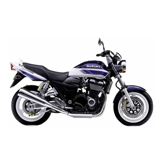
Page 6: Suzuki Gsx1400K2 (2002-Model)
1-4 GENERAL INFORMATION SUZUKI GSX1400K2 (2002-MODEL) RIGHT SIDE LEFT SIDE * Difference between photograph and actual motorcycle depends on the markets. SERIAL NUMBER LOCATION The frame serial number or V.I.N. (Vehicle Identification Number) A is stamped on the right side of the steering head pipe. The engine serial number B is located on the rear side of the crank- case. -
Page 7: Fuel And Oil Recommendation
www.GSX1400FE.com GENERAL INFORMATION 1-5 FUEL AND OIL RECOMMENDATION FUEL Gasoline used should be graded 91 octane (Research Method) or higher. An unleaded gasoline is recom- mended. ENGINE OIL Use a premium quality 4-stroke motor oil to ensure longer ser- vice life of your motorcycle. Use only oils which are rated SF or SG under the API service classification. -
Page 8: Break-In Procedures
www.GSX1400FE.com 1-6 GENERAL INFORMATION BREAK-IN PROCEDURES During manufacture only the best possible materials are used and all machined parts are finished to a very high standard but it is still necessary to allow the moving parts to “BREAK-IN” before subjecting the engine to maximum stresses. -
Page 9: Information Labels
GENERAL INFORMATION 1-7 INFORMATION LABELS GSX1400 GSX1400UD 1 Noise label For E-24 2 Fuel caution label For E-02, 24 3 Tire pressure label 4 Warning safety label 5 ID plate For E-02, 19, 24 6 Loading capacitiy unit: mm... -
Page 10: Specifications
www.GSX1400FE.com 1-8 GENERAL INFORMATION SPECIFICATIONS DIMENSIONS AND DRY MASS Overall length ..............2 160 mm (85.0 in) Overall width ..............810 mm (31.9 in) Overall height ..............1 140 mm (44.9 in) Wheelbase ..............1 520 mm (59.8 in) Ground clearance ............130 mm (5.1 in) Seat height .............. - Page 11 www.GSX1400FE.com GENERAL INFORMATION 1-9 CHASSIS Front suspension ............Telescopic, coil spring, oil damped Rear suspension ............Swingarm, coil spring, oil damped Front suspension stroke ..........130 mm (5.1 in) Rear wheel travel ............123 mm (4.7 in) Caster ................26° Trail ................
-
Page 12: Country And Area Codes
1-10 GENERAL INFORMATION COUNTRY AND AREA CODES The following codes stand for the applicable country(-ies) and area(-s). MODEL CODE COUNTRY or AREA E-02 U.K. GSX1400 E-19 E-24 Australia GSX1400UD E-19... - Page 13 www.GSX1400FE.com PERIODIC MAINTENANCE 2-1 PERIODIC MAINTENANCE CONTENTS PERIODIC MAINTENANCE SCHEDULE ......... 2- 2 PERIODIC MAINTENANCE CHART ..........2- 2 LUBRICATION POINTS..............2- 3 MAINTENANCE AND TUNE-UP PROCEDURES ......2- 4 AIR CLEANER ................2- 4 SPARK PLUG ................2- 5 VALVE CLEARANCE ..............
-
Page 14: Periodic Maintenance Schedule
www.GSX1400FE.com 2-2 PERIODIC MAINTENANCE PERIODIC MAINTENANCE SCHEDULE The chart below lists the recommended intervals for all the required periodic service work necessary to keep the motorcycle operating at peak performance and economy. Maintenance intervals are expressed in terms of kilometer, miles and months, and are dependant on whichever comes first. NOTES: More frequent servicing may be performed on motorcycles that are used under severe conditions. -
Page 15: Lubrication Points
www.GSX1400FE.com PERIODIC MAINTENANCE 2-3 LUBRICATION POINTS Proper lubrication is important for smooth operation and long life of each working part of the motorcycle. Major lubrication points are indicated below. Brake lever holder Brake pedal pivot and footrest pivot Clutch lever holder Drive chain Side-stand pivot and spring hook... -
Page 16: Maintenance And Tune-Up Procedures
www.GSX1400FE.com 2-4 PERIODIC MAINTENANCE MAINTENANCE AND TUNE-UP PROCEDURES This section describes the servicing procedures for each item mentioned in the Periodic Maintenance chart. AIR CLEANER • Remove the fuel tank. • Remove the fuel tank bracket. • Remove the air cleaner element by removing the screws. •... -
Page 17: Spark Plug
www.GSX1400FE.com PERIODIC MAINTENANCE 2-5 SPARK PLUG SPARK PLUG AND SPARK PLUG CAP REMOVAL • Remove the seat. • Remove the fuel tank. ( 4-48) • Remove all spark plug caps. • Remove the spark plugs with a spark plug wrench. HEAT RANGE •... -
Page 18: Valve Clearance
www.GSX1400FE.com 2-6 PERIODIC MAINTENANCE ELECTRODE’S CONDITION • Check the condition of the electrode. • If it is extremely worn or burnt, replace the spark plug. Replace the spark plug if it has a broken insulator, damaged thread, etc. Check the thread size and reach when replacing the spark plug. - Page 19 www.GSX1400FE.com PERIODIC MAINTENANCE 2-7 • Remove the engine oil cooler bolts. • Remove the engine oil cooler hose clamp. • Move the engine oil cooler forward. • Disconnect the cooling fan lead wire coupler. • Remove the oil hose clamp bolts. •...
- Page 20 www.GSX1400FE.com 2-8 PERIODIC MAINTENANCE The valve clearance specification is different for intake and ex- haust valves. Valve clearance must be checked and adjusted, 1) at the time of periodic inspection, 2) when the valve mechanism is serviced, and 3) when the camshafts are disturbed by removing them for servicing.
- Page 21 www.GSX1400FE.com PERIODIC MAINTENANCE 2-9 • When the lines face each other, measure • marked valve clear- ances. • Turn the crankshaft 360° and measure • marked valve clear- ances. • Measure the valve clearances with a thickness gauge. 09900-20803: Thickness gauge VALVE CLEARANCE ADJUSTMENT The clearance is adjusted by replacing the existing tappet shim by a thicker or thinner shim.
- Page 22 www.GSX1400FE.com 2-10 PERIODIC MAINTENANCE NOTE: * Be sure to apply engine oil to tappet shim top and bottom faces. * When seating the tappet shim, be sure to face figure printed surface to the tappet. Reinstall the camshafts as the specified manner. 3-74) •...
- Page 23 www.GSX1400FE.com PERIODIC MAINTENANCE 2-11 (INTAKE SIDE)
- Page 24 www.GSX1400FE.com 2-12 PERIODIC MAINTENANCE (EXHAUST SIDE)
-
Page 25: Engine Oil And Oil Filter
www.GSX1400FE.com PERIODIC MAINTENANCE 2-13 ENGINE OIL AND OIL FILTER Oil should be changed while the engine is warm. Oil filter replace- ment at the specified intervals, should be done together with the engine oil change. ENGINE OIL REPLACEMENT • Keep the motorcycle upright. •... -
Page 26: Fuel Hose
TER. Other manufacturer’s oil filters may differ in thread specifications (thread diameter and pitch), filtering per- formance and durability which may lead to engine dam- age or oil leaks. Also, do not use a genuine Suzuki auto- mobile oil filter on this motorcycle. FUEL HOSE Inspect the fuel hose 1 for damage and fuel leakage. -
Page 27: Throttle Valve Synchronization
www.GSX1400FE.com PERIODIC MAINTENANCE 2-15 THROTTLE VALVE SYNCHRONIZATION Inspect throttle valve synchronization periodically. ( 4-66) THROTTLE CABLE PLAY Adjust the throttle cable play A as follows. MINOR ADJUSTMENT 1st step: • Loosen the locknut 1 of the throttle returning cable 2 and fully turn in the adjuster 3. -
Page 28: Clutch
www.GSX1400FE.com 2-16 PERIODIC MAINTENANCE MAJOR ADJUSTMENT • Lift and support the fuel tank with its prop stay. ( 4-48) • Loosen the lock nuts 1 of the throttle returning cable 2. • Turn the returning cable adjuster 3 to obtain proper cable play. •... -
Page 29: Drive Chain
www.GSX1400FE.com PERIODIC MAINTENANCE 2-17 BLEEDING AIR FROM THE CLUTCH FLUID CIRCUIT The clutch fluid circuit may be purged of air in the following man- ner. • Keep the motorcycle upright and place the handlebars straight. • Fill up the master cylinder reservoir to the upper end of the inspection window. - Page 30 www.GSX1400FE.com 2-18 PERIODIC MAINTENANCE CHECKING • Loosen the axle nut 1. • Loosen the chain adjuster lock nuts 2. • Loosen the torque link nut (Rear) 3. • Tense the drive chain fully by turning both chain adjusters 4. • Count out 21 pins (20 pitches) on the chain and measure the distance between the two points.
-
Page 31: Brake
* Do not use any oil sold commercially as “drive chain oil”. Such oil can damage the O-rings. * The standard drive chain is a RK GB50GSVZ3 Suzuki recommends to use this standard drive chain as a re- placement. - Page 32 www.GSX1400FE.com 2-20 PERIODIC MAINTENANCE BRAKE PADS FRONT BRAKE • The extent of brake pad wear can be checked by observing the grooved limit line A on the pad. When the wear exceeds the grooved limit line, replace the pads with new ones. 6-50) Replace the brake pads as a set, otherwise braking per- formance will be adversely affected.
- Page 33 www.GSX1400FE.com PERIODIC MAINTENANCE 2-21 BRAKE LIGHT SWITCH • Adjust the rear brake light switch so that the brake light will come on just before pressure is felt when the brake pedal is depressed. AIR BLEEDING THE BRAKE FLUID CIRCUIT Air trapped in the brake fluid circuit acts like a cushion to absorb a large proportion of the pressure developed by the master cylin- der and thus interferes with the full braking performance of the brake caliper.
-
Page 34: Tire
www.GSX1400FE.com 2-22 PERIODIC MAINTENANCE • Close the air bleeder valve and disconnect the hose. Fill the reservoir with brake fluid to the top of the inspection window. Air bleeder valve: 8 N . m (0.8 kgf . m, 6.0 Ib-ft) Handle brake fluid with care: the fluid reacts chemically with paint, plastics, rubber materials, etc. -
Page 35: Steering
www.GSX1400FE.com PERIODIC MAINTENANCE 2-23 TIRE PRESSURE If the tire pressure is too high or too low, steering will be ad- versely affected and tire wear will increase. Therefore, maintain the correct tire pressure for good roadability and a longer tire life. Cold inflation tire pressure is as follows. -
Page 36: Front Fork
www.GSX1400FE.com 2-24 PERIODIC MAINTENANCE FRONT FORK Inspect the front forks for oil leakage, scoring or scratches on the outer surface of the inner tubes. Replace any defective parts, if necessary. ( 6-13) REAR SUSPENSION Inspect the rear shock absorbers for oil leakage and check that there is no play in the swingarm. -
Page 37: Chassis Bolt And Nut
www.GSX1400FE.com PERIODIC MAINTENANCE 2-25 CHASSIS BOLTS AND NUTS Check that all chassis bolts and nuts are tightened to their specified torque. The locations of the following nuts and bolts on the motorcycle.: 2-26 N . m kgf . m Item Ib-ft 1 Steering stem head nut 47.0... - Page 38 www.GSX1400FE.com 2-26 PERIODIC MAINTENANCE...
-
Page 39: Compression Pressure Check
www.GSX1400FE.com PERIODIC MAINTENANCE 2-27 COMPRESSION PRESSURE CHECK The compression pressure reading of a cylinder is a good indicator of its internal condition. The decision to overhaul the cylinder is often based on the results of a compression test. Periodic mainte- nance records kept at your dealership should include compression readings for each maintenance service. -
Page 40: Oil Pressure Check
www.GSX1400FE.com 2-28 PERIODIC MAINTENANCE OIL PRESSURE CHECK Check the engine oil pressure periodically. This will give a good indication of the condition of the moving parts. OIL PRESSURE SPECIFICATION 300 – 600 kPa (3.0 – 6.0 kgf/cm , 43 – 85 psi) at 3 000 r/min., Oil temp. at 60°C (140°F) If the oil pressure is lower or higher than the specification, the following causes may be considered. - Page 41 www.GSX1400FE.com ENGINE 3-1 ENGINE CONTENTS ENGINE COMPONENTS REMOVABLE WITH THE ENGINE IN PLACE ..............3- 2 ENGINE REMOVAL AND INSTALLATION ........3- 3 ENGINE REMOVAL ............... 3- 3 ENGINE INSTALLATION ............... 3- 8 ENGINE DISASSEMBLY ..............3-11 ENGINE COMPONENTS INSPECTION AND SERVICE ....3-22 PAIR VALVE ...................
- Page 42 www.GSX1400FE.com 3-2 ENGINE ENGINE COMPONENTS REMOVABLE WITH ENGINE IN PLACE The parts listed below can be removed and reinstalled without removing the engine from the frame. Refer to page listed in each section for removal and reinstallation instructions. ENGINE CENTER ITEM REMOVAL INSPECTION...
-
Page 43: Engine Removal And Installation
www.GSX1400FE.com ENGINE 3-3 ENGINE REMOVAL AND INSTALLATION ENGINE REMOVAL Before taking the engine out of the frame, wash the engine using a steam cleaner. Engine removal is sequentially explained in the following steps. Reinstall the engine by reversing the removal pro- cedure. - Page 44 www.GSX1400FE.com 3-4 ENGINE OIL COOLER • Remove the cooling fan coupler (2P). • Remove the oil hose union and oil hose guide. • With the oil cooler bolts removed,detach the oil cooler and cool- ing fan. EXHAUST PIPE AND MUFFLER •...
- Page 45 www.GSX1400FE.com ENGINE 3-5 IGNITION COIL • With the ignition coil couplers and plug caps disconnected, re- move the ignition coil brackets (R, L). • Disconnect the CMP sensor. • Disconnect the breather hose. • Remove the throttle body assembly. ( 4-55) ELECTRIC PARTS •...
- Page 46 www.GSX1400FE.com 3-6 ENGINE • Disconnect the gear position switch coupler (3P) 1 and side- stand switch coupler (2P) 2. • Remove the starter motor lead wire. GEARSHIFT LEVER • Disconnect the gearshift lever linkage. ENGINE SPROCKET • Remove the engine sprocket cover. •...
- Page 47 www.GSX1400FE.com ENGINE 3-7 • Remove the clutch push rod 1. • Remove the speed sensor rotor 2. • Remove the engine sprocket nut 3 and the washer. • Remove the cotter pin. (For E-03, 28, 33) • Loosen the rear axle nut and the rear torque link nut. •...
-
Page 48: Engine Installation
www.GSX1400FE.com 3-8 ENGINE ENGINE INSTALLATION Install the engine in the reverse order of engine removal. Pay attention to the following points: NOTE: Hang the drive chain on the driveshaft when installing the engine. ENGINE MOUNT • Install the engine and tighten the engine mounting bolts and nuts. - Page 49 Speed sensor rotor bolt: 20 N . m (2.0 kgf . m, 14.8 lb-ft) • Apply grease to the clutch push rod and clutch release piston, and install it. 99000-25010: SUZUKI SUPER GREASE “A” CLUCH RELEASE CYLINDER • Install the clutch release cylinder housing.
- Page 50 www.GSX1400FE.com 3-10 ENGINE EXHAUST PIPE/ MUFFLER • Install the exhaust pipes and mufflers as shown in illustration. Replace the gaskets with new ones. 23 N . m (2.3 kgf . m, 16.5 lb-ft) 24 N . m Identification Use a new gasket. (2.4 kgf .
-
Page 51: Engine Disassembly
www.GSX1400FE.com ENGINE 3-11 ENGINE DISASSEMBLY Identify the position of each removed part. Organize the parts in their respective groups (e.g., intake, exhaust) so that they can be reinstalled in their original positions. CYLINDER HEAD COVER • Remove the PAIR reed valve cover and reed valve. •... - Page 52 www.GSX1400FE.com 3-12 ENGINE • Set the #1 cylinder at TDC. Turn the crankshaft to bring the “T” line on the rotor to the tip of signal generator, and the lines on camshaft facing outside. • Remove the cam chain tension adjuster cap, the washer, the spring and the steel ball.
- Page 53 www.GSX1400FE.com ENGINE 3-13 CYLINDER HEAD • Remove the oil hose. • Loosen the cylinder nut A. • Remove the cylinder head bolts (M6). • Remove the cylinder head bolts and nuts. NOTE: When loosening the cylinder head bolts and nuts, loosen each bolt little by little diagonally.
- Page 54 www.GSX1400FE.com 3-14 ENGINE • Remove the cylinder head gasket and dowel pins. • With both end of cylinder evenly rised, remove the cylinder. PISTON • Put the rag under the piston so as not to drop the parts into the crankcase, remove the piston pin circlip.
- Page 55 www.GSX1400FE.com ENGINE 3-15 SIGNAL GENERATOR • With the rotor held, remove the signal generator rotor bolt. • Remove the signal generator. • Remove the oil pressure switch 1. OIL FILTER • Remove the oil filter. 09915-40610: Oil filter wrench COOLING FAN SWITCH •...
- Page 56 www.GSX1400FE.com 3-16 ENGINE CLUTCH • Remove the clutch cover. • With the clutch spring bolts removed, detach the clutch springs and clutch pressure plate. • Remove the clutch push piece 1, the bearing 2 and the thrust washer 3. • Remove the clutch push rod 4. NOTE: If it is difficult to pull out the push rod 4 , use a magnetic hand or a wire.
- Page 57 www.GSX1400FE.com ENGINE 3-17 • Remove the wave washer 1, the back torque limiter 2 and the clutch sleeve hub. • Remove the washer 3 and the primary driven gear assembly. • Remove the spacer, the bearing and the washer. OIL PUMP DRIVEN GEAR •...
- Page 58 www.GSX1400FE.com 3-18 ENGINE GENERATOR COVER • Remove the generator cover. • Remove the starter idle gear and its shaft. GENERATOR ROTOR/STARTER CLUTCH • Hold the generator rotor with the special tool and remove the generator rotor bolt. 09930-44530: Rotor holder •...
- Page 59 www.GSX1400FE.com ENGINE 3-19 OIL PAN • Remove the oil pan. • Remove the oil pressure regulator. • Remove the oil pipes, 1 and 2. • Remove the crank balancer guard 3. • Remove the oil strainer 4 and its O-ring. CRANK BALANCER •...
- Page 60 www.GSX1400FE.com 3-20 ENGINE CRANK CASE • Remove the lower crankcase bolts, (6 mm) and (8 mm). • Remove the upper crankcase bolts, (6 mm) and (8 mm). • Remove the crank journal bolts (9 mm). NOTE: Loosen the crank journal bolts in the descending order of the number on crankcase.
- Page 61 www.GSX1400FE.com ENGINE 3-21 • Remove the O-rings and the dowel pins. CRANKSHAFT • Remove the crankshaft thrust bearings 1. • Remove the crankshaft together with the cam chain. TRANSMISSION • Remove the countershaft and the driveshaft. • Remove the C-ring 2 and the dowel pins 3.
-
Page 62: Engine Components Inspection And Service
www.GSX1400FE.com 3-22 ENGINE ENGINE COMPONENTS INSPECTION AND SERVICE Identify the position of each removed part. Organize the parts in their respective groups (i.e., intake, exhaust, No.1 or No.2) so that they can be installed in their original locations. PAIR VALVE REMOVAL AND INSTALLATION •... -
Page 63: Cylinder Head Cover
• With the grease applied to the O-ring, install the cam position sensor. Cam position sensor bolt: 10 N . m (1.0 kgf . m, 7.4 lb-ft) 99000-25010: SUZUKI SUPER GREASE “A” OIL GALLERY PLUG • Install the gasket and the oil gallery plug. - Page 64 www.GSX1400FE.com 3-24 ENGINE CAMSHAFT JOURNAL WEAR • Determine whether or not each journal is worn down to the limit by measuring the oil clearance with the camshaft installed in place. • Use the plastigauge to read the clearance at the widest por- tion, which is specified as follows: Camshaft journal oil clearance: Standard: (IN &...
-
Page 65: Cam Chain Tension Adjuster
www.GSX1400FE.com ENGINE 3-25 CAM SPROCKET • Inspect the sprocket teeth for wear. • If they are worn, replace the sprocket/camshaft assembly and cam chain as a set. • Install the cam sprocket to the camshaft. ( 3-75) • Apply a small quantity of thread lock to the cam sprocket bolt and tighten it to the specified torque. -
Page 66: Cylinder Head And Valve
www.GSX1400FE.com 3-26 ENGINE CYLINDER HEAD AND VALVE VALVE AND VALVE SPRING DISASSEMBLY • Remove the tappets and shims by fingers or magnetic hand. Identify the position of each removed part. • Using special tools, compress the valve springs and remove the two cotter halves 1 from valve stem. - Page 67 www.GSX1400FE.com ENGINE 3-27 VALVE STEM DEFLECTION • Lift the valve about 10 mm (0.39 in) from the valve seat. • Measure the valve stem deflection in two directions, perpen- dicular to each other, by positioning the dial gauge as shown. •...
- Page 68 www.GSX1400FE.com 3-28 ENGINE VALVE SPRING The force of the coil springs keeps the valve seat tight. Weakened springs result in reduced engine power output, and often account for the chattering noise coming from the valve mechanism. • Check the valve springs for proper strength by measuring their free length and also by the force required to compress them.
- Page 69 www.GSX1400FE.com ENGINE 3-29 VALVE GUIDE SERVICING • Using the valve guide remover, drive the valve guide out to- ward the intake or exhaust camshaft side. ! 09916-53310: Valve guide remover/installer NOTE: * Discard the removed valve guide subassemblies. * Only oversized valve guides are available as replacement parts. (Part No.
- Page 70 www.GSX1400FE.com 3-30 ENGINE VALVE SEAT WIDTH INSPECTION • Visually check for valve seat width on each valve face. • If the valve face has worn abnormally, replace the valve. • Coat the valve seat with Prussian Blue and set the valve in place.
- Page 71 www.GSX1400FE.com ENGINE 3-31 INITIAL SEAT CUT • Install the 45° cutter 2, attachment 3 and T-handle 4. • Using the 45° cutter, descale and clean up the seat. Rotate the cutter one or two turns. • Measure the valve seat width W after every cut. 45°...
- Page 72 www.GSX1400FE.com 3-32 ENGINE BOTTOM NARROWING CUT (IN.) • If the contact area W is too wide or too low, use the 60° cutter to narrow and raise the contact area. 60° FINAL SEAT CUT Contact area too low and too •...
- Page 73 www.GSX1400FE.com ENGINE 3-33 VALVE AND VALVE SPRING REASSEMBLY • Apply molybdenum oil solution to each oil seal, and press-fit them into position with the valve guide installer. 09916-43210: Valve guide remover/installer MOLYBDENUM OIL SOLUTION Do not reuse the removed oil seals. •...
-
Page 74: Cylinder
www.GSX1400FE.com 3-34 ENGINE OIL GALLERY • Install the washer and the oil gallery plug. Oil gallery plug: 20 N . m (2.0 kgf . m, 15 lb-ft) INTAKE PIPE • Install the intake pipes. CYLINDER CYLINDER DISTORTION • Check the gasket surface of the cylinder for distortion with a straightedge and thickness gauge, taking a clearance reading at several places as indicated. -
Page 75: Piston And Piston Ring
www.GSX1400FE.com ENGINE 3-35 PISTON AND PISTON RING PISTON DIAMETER • Using a micrometer, measure the piston outside diameter at 15 mm (0.6 in) from the piston skirt end. • If the measurement is less than the limit, replace the piston. Piston diameter: Standard: 80.980 –... - Page 76 www.GSX1400FE.com 3-36 ENGINE PISTON RING TO GROOVE CLEARANCE • Measure the side clearances of the 1st and 2nd piston rings using the thickness gauge. • If any of the clearances exceed the limit, replace both the pis- ton and piston rings. 09900-20803: Thickness gauge 09900-20205: Micrometer (0 –...
-
Page 77: Clutch
www.GSX1400FE.com ENGINE 3-37 CLUTCH CLUTCH DRIVE PLATES INSPECTION NOTE: Wipe off engine oil from the clutch drive plates with a clean rag. • Measure the thickness of drive plates with a vernier calipers. • If each drive plate thickness is less than the limit, replace it with a new one. -
Page 78: Gearshift System
www.GSX1400FE.com 3-38 ENGINE GEARSHIFT SYSTEM GEARSHIFT SHAFT/GEARSHIFT ARM DISASSEMBLY • Remove the following parts from the gearshift shaft/gearshift arm. 1 Washer 5 Plate return spring 2 Circlip 6 Washer 3 Gearshift shaft return spring 7 Circlip 4 Gearshift cam drive plate 09900-06107: Snap ring pliers GEARSHIFT SHAFT/GEARSHIFT ARM INSPECTION •... - Page 79 www.GSX1400FE.com ENGINE 3-39 BACK TORQUE LIMITER • Inspect the back torque limiter for wear or damage. If any de- fects are found, replace it with a new one. • Apply a small quantity of thread lock to the clutch spring guide bolt and tighten it.
-
Page 80: Generator
www.GSX1400FE.com 3-40 ENGINE GENERATOR INSPECTION: REASSEMBLY • When installing the generator stator set bolts, tighten them to the specified torque. Generator stator set bolt: 10 N . m (1.0 kgf . m, 7.4 lb-ft) NOTE: Be sure to install the grommet to the generator cover. STARTER CLUTCH INSPECTION •... -
Page 81: Oil Pressure Regulator/Oil Strainer
www.GSX1400FE.com ENGINE 3-41 OIL PRESSURE REGULATOR • Inspect the operation of the oil pressure regulator by pushing on the piston with a proper bar. • If the piston does not operate, replace the oil pressure regula- tor with a new one. OIL STRAINER •... -
Page 82: Transmission
www.GSX1400FE.com 3-42 ENGINE TRANSMISSION • Disassemble the countershaft and driveshaft. Pay attention to the following points: 09900-06104: Snap ring pliers • Slide the 6th (TOP) drive gear circlip B from its groove towards the 3rd/4th drive gears. • Slide the 2nd drive gear towards the 6th (TOP) drive gear, then remove the 2nd drive gear circlip A. - Page 83 * Rotate the bearings by hand to inspect for smooth rotation. Re- place the bearings if there is anything unusual. * Before installing the gears, apply engine oil to the driveshaft and countershaft. * Before installing the oil seal, apply grease to oil seal. 99000-25010: SUZUKI SUPER GREASE “A”...
- Page 84 www.GSX1400FE.com 3-44 ENGINE Thrust * Never reuse a circlip. After a circlip has been removed from a shaft, it should be discarded and a new circlip must be installed. Circlip * When installing a new circlip, do not expand the end gap larger than required to slip the circlip over the shaft.
-
Page 85: Crankshaft And Conrod
www.GSX1400FE.com ENGINE 3-45 CRANKSHAFT AND CONROD CRANKSHAFT RUNOUT • Support the crankshaft with “V” blocks as shown, with the two end journals resting on the blocks. • Set up the dial gauge, as shown. • Rotate the crankshaft slowly to read the runout. •... - Page 86 www.GSX1400FE.com 3-46 ENGINE CONROD-CRANK PIN BEARING INSPECTION • Inspect the bearing surfaces for any sign of fusion, pitting, burn, or flaws. If any, replace them with a specified set of bearings. • If the oil clearance exceeds the service limit, select the speci- fied bearings from the bearing selection table.
- Page 87 www.GSX1400FE.com ENGINE 3-47 • Check the corresponding conrod I.D. code number A stamped on the conrod. • Check the corresponding crank pin O.D. code number B stamped on the crankshaft. Bearing selection table Crank pin O.D. B Code Conrod Green Black Brown I.D.
- Page 88 www.GSX1400FE.com 3-48 ENGINE INSTALLATION • When fitting the bearing to the bearing cap and conrod, be sure to fix the stopper part A first and press in the other end. Be sure to clean the conrod big end. • Apply molybdenum oil solution to the crank pin and bearing surface.
-
Page 89: Crankshaft Journal Bearing
www.GSX1400FE.com ENGINE 3-49 CRANKSHAFT JOURNAL BEARING INSPECTION • Inspect each bearing of upper and lower crankcases for any damage. SELECTION • Place the plastigauge axially along the crankshaft journal, avoid- ing the oil hole, as shown. 09900-22301: Plastigauge Never rotate the crankshaft when a piece of plastigauge is installed. - Page 90 www.GSX1400FE.com 3-50 ENGINE • Check the corresponding crankcase journal I.D.code number A stamped on the upper crankcase. • Check the corresponding crankshaft journal O.D.code number B stamped on the crankshaft. Bearing selection table Crankshaft journal O.D. B Code Crankcase Green Black Brown I.D.
-
Page 91: Crankshaft Thrust Bearing
www.GSX1400FE.com ENGINE 3-51 CRANKSHAFT THRUST BEARING • With the crankshaft, right-side thrust bearing and left-side thrust bearing inserted in the upper crankcase, measure the thrust clearance on the left side by using the thickness gauge. 1: Right-side thrust bearing 2: Left-side thrust bearing NOTE: Pull the crankshaft to the left-side, so that there is no clearance on the right-side thrust bearing. - Page 92 www.GSX1400FE.com 3-52 ENGINE Thrust bearing selection table Clearance before Color Thrust bearing inserting left-side Thrust clearance (Part No.) thickness thrust bearing 2.560 – 2.585 mm White 2.475 – 2.500 mm 0.060 – 0.110 mm (0.1008 – 0.1018 in) (12228-24F00-0F0) (0.0974 – 0.0984 in) (0.0024 –...
-
Page 93: Crankcase/Oil Pan
www.GSX1400FE.com ENGINE 3-53 CRANKCASE/OIL PAN OIL CHECK VALVE • Install the oil check valve. Oil check valve: 35 N . m (3.5 kgf . m, 26 lb-ft) LOWER CRANKCASE • Inspect the gearshift shaft bearings (1 and 2) and the gear- shift cam bearing 3 for abnormal noise and smooth rotation while they are in the crankcase. - Page 94 www.GSX1400FE.com 3-54 ENGINE • Remove the gearshift cam bearing using the special tools. 09923-74510: Bearing remover 09930-30102: Sliding shaft • Install the bearing using the special tool. 09913-70210: Bearing installer set (30 mm) OIL JET Removal • Remove the piston cooling oil jets 1 from the upper crankcase. •...
- Page 95 www.GSX1400FE.com ENGINE 3-55 OIL GALLERY PLUG • Install each plug. 1Main gallery plug: 35 N . m (3.5 kgf . m, 26 lb-ft) 2Main gallery plug: 21 N . m (2.1 kgf . m, 15 lb-ft) 3Sub gallery plug: 35 N . m (3.5 kgf . m, 26 lb-ft) 4Sub gallery plug: 10 N .
-
Page 96: Engine Reassembly
OIL PUMP • Install the dowel pins. • Apply grease to the O-ring, install the oil pump assembly. 99000-25010: SUZUKI SUPER GREASE “A” • Apply a small quantity of thread lock to the bolts and tighten them. 99000-32050: THREAD LOCK “1342”... - Page 97 www.GSX1400FE.com ENGINE 3-57 • Apply a small quantity of THREAD LOCK to the bearing re- tainer screws and the shift fork shaft retainer screw and tighten them. 99000-32050: THREAD LOCK “1342” • Tighten the gearshift shaft spring stopper. Gearshift shaft spring stopper: 10 N .
- Page 98 www.GSX1400FE.com 3-58 ENGINE TRANSMISSION • Install the bearing pins 1 and the C-ring 2 on the upper crank- case. • Install the countershaft assembly on the upper crankcase. NOTE: Align the C-ring with the groove on the bearing and the bearing pin with the indent on the bearing.
- Page 99 ENGINE 3-59 • Apply SUZUKI BOND to the mating surface of the lower crank- case. 99000-31140: SUZUKI BOND “1207B” NOTE: Use of SUZUKI BOND is as follows: * Make surfaces free from moisture, oil, dust and other foreign materials.
- Page 100 www.GSX1400FE.com 3-60 ENGINE • Match the upper and lower crankcases. • Tighten the crank journal bolt (9 mm) in ascending order of numbers assigned to these bolts. Tighten each bolt a little at a time to equalize the pressure as following two steps. Crank journal bolt: (M9) initial: 18 N .
- Page 101 • Apply a small quantity of thread lock to the bolt and install the balancer cover. 99000-32050: THREAD LOCK “1342” Balancer cover bolt: 10 N . m (1.0 kgf . m, 7.4 lb-ft) OIL PIPE • Apply grease to the O-rings and install the main gallery oil pipe. 99000-25010: SUZUKI SUPER GREASE “A”...
- Page 102 OIL STRAINER • With grease applied to the O-ring, install the oil strainer. 99000-25010: SUZUKI SUPER GREASE “A” Oil strainer bolt: 10 N . m (1.0 kgf . m, 7.4 lb-ft) • Apply grease to the O-ring and install it with the shim.
- Page 103 GEAR POSITION SWITCH • Install the gear position switch contacts and the springs. • Apply grease to the O-ring. 99000-25010: SUZUKI SUPER GREASE “A” • Install the gear position switch as shown. GENERATOR • Degrease the tapered portion of the generator rotor and also the crankshaft.
- Page 104 3-64 ENGINE GENERATOR COVER • Apply SUZUKI BOND lightly to the mating surfaces at the part- ing line between the upper and lower crankcases as shown. 99000-31140: SUZUKI BOND “1207B” • Install the dowel pins and new gasket. • Install the generator cover and tighten the generator cover bolts to the specified torque.
- Page 105 www.GSX1400FE.com ENGINE 3-65 • Confirm the gearshift cam stopper movement. • Check the neutral position. • Install the gearshift cam stopper plate after aligning the gear- shift cam pin with the gearshift cam stopper plate hole. • Apply a small quantity of THREAD LOCK to the gearshift cam stopper plate bolt and tighten it to the specified torque.
- Page 106 www.GSX1400FE.com 3-66 ENGINE • Install the primary driven gear assembly and apply engine oil to the needle bearing. • Install the thrust washer 1. NOTE: Be sure to engage the oil pump drive and driven gears, primary drive and driven gears. •...
- Page 107 www.GSX1400FE.com ENGINE 3-67 • Insert the spring washer seat 1 and the spring washer 2. • Insert the clutch drive plates and driven plates one by one into the clutch sleeve hub in the prescribed order as shown in the illustration.
- Page 108 Clutch spring set bolt: 10 N . m (1.0 kgf . m, 7.4 lb-ft) NOTE: Tighten the clutch spring set bolts diagonally. CLUTCH COVER • Apply SUZUKI BOND lightly to the mating surfaces at the part- ing line between the upper, middle and lower crankcases as shown. 99000-31140: SUZUKI BOND “1207B”...
- Page 109 www.GSX1400FE.com ENGINE 3-69 COOLING FAN SWITCH • Install the gasket and the cooling fan switch. Cooling fan switch: 17 N . m (1.7 kgf . m, 13 lb-ft) OIL FILTER • Install the oil filter using the special tool. ( 2-13) 09915-40610: Oil filter wrench OIL PRESSURE SWITCH...
- Page 110 Install the engine ground lead wire and clamp to the bolt A . STARTER MOTOR • Apply grease to the O-ring and install the starter motor. 99000-25010: SUZUKI SUPER GREASE “A” Starter motor mounting bolt: 6 N . m (0.6 kgf . m, 4.4 lb-ft) OIL TEMPERATURE SENSOR •...
- Page 111 www.GSX1400FE.com ENGINE 3-71 PISTON • Install the piston rings in the order of oil ring, 2nd ring and 1st ring. • The first member to go into the oil ring groove is a spacer 1. After placing the spacer, fit the two side rails 2. NOTE: Side designations, top and bottom, are not applied to the spacer and side rails: you can position each either way.
- Page 112 • Tighten cylinder nut A temporarily. CYLINDER HEAD • Apply grease to the O-rings and insert the oil return pipes to the crankcase. " 99000-25010: SUZUKI SUPER GREASE “A” • Fit the dowel pins and the new cylinder head gasket to the cylinder.
- Page 113 www.GSX1400FE.com ENGINE 3-73 • Place the cylinder head on the cylinder. • Apply engine oil to the threads of cylinder head bolt and the copper washers. • Install the cylinder head plate 1 and tighten the cylinder head bolts and nuts (M10) to the specified two-step torque with a torque wrench sequentially and diagonally.
- Page 114 www.GSX1400FE.com 3-74 ENGINE • Install the cylinder head oil hose. Cylinder head oil hose union bolt: 20 N . m (2.0 kgf . m, 15 lb-ft) • Install the oil pipe with the white paint facing exhaust side. • Install and tighten the oil pipe bolts with the washers. Oil pipe bolt: 10 N .
- Page 115 www.GSX1400FE.com ENGINE 3-75 POSITION OF CAMSHAFTS AND CAM SPROCKETS...
- Page 116 www.GSX1400FE.com 3-76 ENGINE • Apply molybdenum oil solution to journals and cam faces. MOLYBDENUM OIL SOLUTION • Install each dowel pin. • Install the camshaft journal holders by aligning the embossed letters on the camshaft journal holders with the embossed let- ters on the cylinder head.
- Page 117 • Install the cam chain guide. Cam chain guide bolt: 10 N . m (1.0 kgf . m, 7.4 lb-ft) SIGNAL GENERATOR COVER • Apply SUZUKI BOND to the grommet and the crankcase mat- ing surface. 99000-31140: SUZUKI BOND “1207B”...
- Page 118 Be sure to check the valve clearance. ( 2-6) • Install the new gaskets to the cylinder head cover. • Apply SUZUKI BOND to the cam end caps of the gaskets as shown. 99000-31230: SUZUKI BOND “1216B” • Place the cylinder head cover on the cylinder head.
-
Page 119: Fi System
www.GSX1400FE.com FI SYSTEM CONTENTS PRECAUTIONS IN SERVICING ............4- 2 FI SYSTEM TECHNICAL FEATURES ..........4- 8 INJECTION TIME ................4- 8 COMPENSATION OF INJECTION TIME........4- 9 INJECTION STOP CONTROL ............4- 9 FUEL DELIVERY SYSTEM ............4-10 FUEL PUMP ................... 4-11 FUEL PRESSURE REGULATOR .......... - Page 120 www.GSX1400FE.com FI SYSTEM FUEL SYSTEM .................. 4-48 FUEL TANK REMOVAL ..............4-48 FUEL TANK INSTALLATION ............4-48 FUEL PRESSURE INSPECTION ..........4-49 FUEL PUMP INSPECTION ............4-50 FUEL PUMP RELAY INSPECTION ..........4-51 FUEL PUMP AND FUEL FILTER REMOVAL ....... 4-51 FUEL MESH FILTER INSPECTION AND CLEANING ....
-
Page 121: Precautions In Servicing
www.GSX1400FE.com 4-2 FI SYSTEM PRECAUTIONS IN SERVICING When handling the FI component parts or servicing the FI sys- tem, observe the following points for the safety of the system. Click CONNECTOR/COUPLER • When connecting a connector, be sure to push it in until a click is felt. - Page 122 www.GSX1400FE.com FI SYSTEM 4-3 FUSE • When a fuse blows, always investigate the cause, correct it and then replace the fuse. • Do not use a fuse of a different capacity. • Do not use wire or any other substitute for the fuse. ECM/VARIOUS SENSORS •...
-
Page 123: Electrical Circuit Inspection Procedure
www.GSX1400FE.com 4-4 FI SYSTEM • Removing any battery terminal of a running engine is strictly prohibited. The moment such removal is made, damaging counter electro- motive force will be applied to the ECM which may result in serious damage. • Before measuring voltage at each terminal, check to make sure that battery voltage is 11V or higher. - Page 124 www.GSX1400FE.com FI SYSTEM 4-5 • Disconnect the negative cable from the battery. • Check each connector/coupler at both ends of the circuit being checked for loose connection. Also check for condition of the coupler lock if equipped. Sensor Check for loose connection •...
- Page 125 www.GSX1400FE.com 4-6 FI SYSTEM VOLTAGE CHECK If voltage is supplied to the circuit being checked, voltage check can be used as circuit check. • With all connectors/couplers connected and voltage applied to the circuit being checked, measure voltage between each ter- minal and body ground.
-
Page 126: Using Testers
If continuity is indicated, the circuit is shorted to the ground between terminals A and B. USING TESTERS • Use the Suzuki multi-circuit tester (09900-25008). • Use well-charged batteries in the tester. • Be sure to set the tester to the correct testing range. -
Page 127: Fi System Technical Features
www.GSX1400FE.com 4-8 FI SYSTEM FI SYSTEM TECHNICAL FEATURES INJECTION TIME (INJECTION VOLUME) The factors to determine the injection time include the basic fuel injection time which is calculated on the basis of the intake air pressure, engine speed and throttle opening angle, and various compensations which are determined according to the signals from various sensors that detect the engine and driving conditions. -
Page 128: Compensation Of Injection Time
www.GSX1400FE.com FI SYSTEM 4-9 COMPENSATION OF INJECTION TIME (VOLUME) The following different signals are output from the respective sensors for compensation of the fuel injection time (volume). SIGNAL DESCRIPTION ATMOSPHERIC PRESSURE SENSOR SIG- When atmospheric pressure is low, the sensor sends the signal to the ECM and reduce the injection time (volume). -
Page 129: Fuel Delivery System
www.GSX1400FE.com 4-10 FI SYSTEM FUEL DELIVERY SYSTEM The fuel delivery system consists of the fuel tank, fuel pump, fuel filters, fuel feed hose, fuel delivery pipe (including fuel injectors) and fuel pressure regulator. There is no fuel return hose. The fuel in the fuel tank is pumped up by the fuel pump and pressurized fuel to flow into the injector installed in the fuel delivery pipe. -
Page 130: Fuel Pump
www.GSX1400FE.com FI SYSTEM 4-11 FUEL PUMP The electric fuel pump is mounted at the bottom of the fuel tank, which consists of the armature, magnet, impeller, brush, check valve and relief valve. The ECM controls its ON/OFF operation as controlled under the FUEL PUMP CONTROL SYSTEM. -
Page 131: Fuel Pressure Regulator
www.GSX1400FE.com 4-12 FI SYSTEM FUEL PRESSURE REGULATOR The fuel pressure regulator consists of the spring and valve. It keeps absolute fuel pressure of 300 kPa (3.0 kgf/cm , 43 psi) applied to the injector at all times. When the fuel pressure rises more than 300 kPa (3.0 kgf/cm , 43 psi), the fuel pushes the valve in the regulator open and excess fuel returns to the fuel tank. -
Page 132: Fuel Pump Control System
www.GSX1400FE.com FI SYSTEM 4-13 FUEL PUMP CONTROL SYSTEM When the ignition switch is turned on, current from the battery flows to the fuel pump motor through the side- stand relay and the fuel pump relay causing the motor to turn. Since the ECM has a timer function, the fuel pump motor stops turning in three seconds after the switch has been turned on. -
Page 133: Ecm (Fi Control Unit)
www.GSX1400FE.com 4-14 FI SYSTEM ECM (FI CONTROL UNIT) The ECM is located under the seat. The ECM consists of CPU (Central Processing Unit), memory (ROM) and I/O (Input/Output) sections. The signal from each sensor is sent to the input section and then sent to CPU. On the basis of signal information received, CPU calculates the volume of fuel necessary for injection using maps programmed for varying engine conditions. -
Page 134: Sensors
www.GSX1400FE.com FI SYSTEM 4-15 SENSORS INTAKE AIR PRESSURE SENSOR (IAP SENSOR) The intake air pressure sensor is located at the upper frame be- tween the tubes and its vacuum hose is connected to the throttle body. The sensor detects the intake air pressure, which is then con- verted into voltage signal and sent to the ECM. - Page 135 www.GSX1400FE.com 4-16 FI SYSTEM CRANKSHAFT POSITION SENSOR (CKP SENSOR) The signal rotor is mounted on the right end of the crankshaft, and the crankshaft position sensor (Pick-up coil) is installed on the right side of the crankcase. The sensor generates the pick-up signal to be supplied to the ECM.
- Page 136 www.GSX1400FE.com FI SYSTEM 4-17 ENGINE OIL TEMPERATURE SENSOR (EOT SENSOR) The engine oil temperature sensor is installed at the upper crank- case. The sensor detects the engine oil temperature in thermistor re- sistance value, which is then converted to voltage signal and sent to the ECM.
- Page 137 www.GSX1400FE.com 4-18 FI SYSTEM TIP OVER SENSOR (TO SENSOR) The tip over sensor is located in ahead of the battery holder. The sensor detects the leaning of the motorcycle. When it leans more than 43°, the mechanical switch turns ON and a signal is sent to the ECM.
-
Page 138: Fi System Parts Location
www.GSX1400FE.com FI SYSTEM 4-19 FI SYSTEM PARTS LOCATION... - Page 139 www.GSX1400FE.com 4-20 FI SYSTEM...
-
Page 140: Fi System Diagram
www.GSX1400FE.com FI SYSTEM 4-21 FI SYSTEM DIAGRAM BATTERY SWITCH STPS RELAY FI # 4 STVA FI # 3 IATS FI # 2 FI # 1 IG COIL CMPS CKPS IAPS STARTER MOTOR STARTER MOTOR EOTS EOTS GP SWITCH GP SWITCH... -
Page 141: Fi System Wiring Diagram
www.GSX1400FE.com 4-22 FI SYSTEM FI SYSTEM WIRING DIAGRAM... -
Page 142: Self-Diagnosis Function
www.GSX1400FE.com FI SYSTEM 4-23 SELF-DIAGNOSIS FUNCTION The self-diagnosis function is incorporated in the ECM. The function has two modes, “User mode” and “Dealer mode”. The user can only be notified by the LCD (DISPLAY) panel and LED (FI light). To check the function of the individual FI system devices, the dealer mode is prepared. -
Page 143: Dealer Mode
www.GSX1400FE.com 4-24 FI SYSTEM DEALER MODE The defective function is memorized in the computer. Use the special tool’s coupler to connect to the dealer mode coupler. The memorized malfunction code is displayed on LCD (DISPLAY) panel. Malfunction means that the ECM does not receive signal from the devices. These affected devices are indicated in the code form. 09930-82710: Mode select switch Before checking the malfunction code, do not disconnect the ECM lead wire couplers. - Page 144 www.GSX1400FE.com FI SYSTEM 4-25 CODE MALFUNCTION PART REMARKS None No defective part Camshaft position sensor (CMPS) Crankshaft position sensor (CKPS) Pick-up coil signal, signal generator Intake air pressure sensor (IAPS) Throttle position sensor (TPS) Engine oil temp. sensor (EOTS) Intake air temp. sensor (IATS) Atmospheric pressure sensor (APS) Tip over sensor (TOS) Ignition signal #1, #4 (IG coil #1, #4)
-
Page 145: Fail-Safe Function
www.GSX1400FE.com 4-26 FI SYSTEM FAIL-SAFE FUNCTION FI system is provided with fail-safe function to allow the engine to start and the motorcycle to run in a mini- mum performance necessary even under malfunction condition. ITEM FAIL-SAFE MODE STARTING ABILITY RUNNING ABILITY Camshaft position ECM determines cylinder as sensor... -
Page 146: Fi System Troubleshooting
www.GSX1400FE.com FI SYSTEM 4-27 FI SYSTEM TROUBLESHOOTING CUSTOMER COMPLAINT ANALYSIS Record details of the problem (failure, complaint) and how it occurred as described by the customer. For this purpose, use of such an inspection form will facilitate collecting information to the point required for proper analysis and diagnosis. -
Page 147: Self-Diagnostic Procedures
www.GSX1400FE.com 4-28 FI SYSTEM SELF-DIAGNOSTIC PROCEDURES • Don’t disconnect couplers from ECM, battery cable from bat- tery, ECM ground wire harness from engine or main fuse be- fore confirming malfunction code (self-diagnostic trouble code) stored in memory. Such disconnection will erase memorized information in ECM memory. -
Page 148: Malfunction Code And Defective Condition
www.GSX1400FE.com FI SYSTEM 4-29 MALFUNCTION CODE AND DEFECTIVE CONDITION DETECTED FAILURE CONDITION MALFUNCTION DETECTED ITEM CODE CHECK FOR NO FAULT ––––––––––– Camshaft position The signal does not reach ECM for more than 4 sec. after re- sensor ceiving the starter signal. The camshaft position sensor wiring and mechanical parts. - Page 149 www.GSX1400FE.com 4-30 FI SYSTEM Secondary throttle When no actuator control signal is supplied from the ECM or valve actuator communication signal does not reach ECM or operation voltage does not reach STVA motor, c28 is indicated. STVA can not operate. STVA lead wire/coupler.
-
Page 150: C11" Cmp Sensor Circuit Malfunction
www.GSX1400FE.com FI SYSTEM 4-31 “C11” CMP SENSOR CIRCUIT MALFUNCTION DETECTED CONDITION POSSIBLE CAUSE No CMP sensor signal for 4 seconds at engine • Metal particles or foreign material being cranking. attached on the CMP sensor and rotor tip. • CMP sensor circuit open or short. •... -
Page 151: C12" Ckp Sensor Circuit Malfunction
www.GSX1400FE.com 4-32 FI SYSTEM “C12” CKP SENSOR CIRCUIT MALFUNCTION DETECTED CONDITION POSSIBLE CAUSE No CKP sensor signal for 3 seconds at engine • Metal particles or foreign material being cranking. attached on the CKP sensor and rotor tips. • CKP sensor circuit open or short. •... -
Page 152: C13" Iap Sensor Circuit Malfunction
www.GSX1400FE.com FI SYSTEM 4-33 “C13” IAP SENSOR CIRCUIT MALFUNCTION DETECTED CONDITION POSSIBLE CAUSE Low pressure and low voltage. • Clogged vacuum passage between throttle High pressure and high voltage. body and IAP sensor. 0.20 V Sensor voltage < 4.80 V •... - Page 153 www.GSX1400FE.com 4-34 FI SYSTEM Remove the IAP sensor. Connect the vacuum pump gauge to the vacuum port of the IAP sensor. Arrange 3 new 1.5 V batteries in series (check that total voltage is 4.5 – 5.0 V) and connect - terminal to the ground terminal and + terminal to the Vcc terminal.
-
Page 154: C14" Tp Sensor Circuit Malfunction
www.GSX1400FE.com FI SYSTEM 4-35 “C14” TP SENSOR CIRCUIT MALFUNCTION DETECTED CONDITION POSSIBLE CAUSE Signal voltage low or high. • TP sensor maladjusted. Difference between actual throttle opening and • TP sensor circuit open or short. opening calculated by ECM in larger than specified •... - Page 155 www.GSX1400FE.com 4-36 FI SYSTEM Connect the TP sensor coupler. Insert the copper wires to the lead wire coupler. Turn the ignition switch ON. Measure the TP sensor output voltage at the coupler (be- tween Yellow and Black wires) by turning the throttle grip. TP sensor output voltage Throttle valve is closed: Approx.
-
Page 156: C15" Eot Sensor Circuit Malfunction
www.GSX1400FE.com FI SYSTEM 4-37 “C15” EOT SENSOR CIRCUIT MALFUNCTION DETECTED CONDITION POSSIBLE CAUSE High engine oil temp. (Low voltage – Low • B/Bl circuit shorted to ground. resistance) • B/Br circuit open. Low engine oil temp. (High voltage – High •... -
Page 157: C21" Iat Sensor Circuit Malfunction
www.GSX1400FE.com 4-38 FI SYSTEM “C21” IAT SENSOR CIRCUIT MALFUNCTION DETECTED CONDITION POSSIBLE CAUSE High intake air temp. (Low voltage – Low • Dg circuit shorted to ground. resistance) • B/Br circuit open. Low intake air temp. (High voltage – High •... -
Page 158: C22" Ap Sensor Circuit Malfunction
www.GSX1400FE.com FI SYSTEM 4-39 “C22” AP SENSOR CIRCUIT MALFUNCTION DETECTED CONDITION POSSIBLE CAUSE Low pressure and low voltage. • Clogged air passage with dust. High pressure and high voltage. • Red wire circuit open or shorted to ground. 0.20 V Sensor Voltage <... - Page 159 www.GSX1400FE.com 4-40 FI SYSTEM Remove the AP sensor. Connect the vacuum pump gauge to the air passage port of the AP sensor. Arrange 3 new 1.5 V batteries in series (check that total voltage is 4.5 – 5.0 V) and connect - terminal to the ground terminal and + terminal to the Vcc terminal.
-
Page 160: C23" To Sensor Circuit Malfunction
www.GSX1400FE.com FI SYSTEM 4-41 “C23” TO SENSOR CIRCUIT MALFUNCTION DETECTED CONDITION POSSIBLE CAUSE No TO sensor signal for more than 2 seconds, • TO sensor circuit open or short. after ignition switch turns ON. • TO sensor malfunction. Sensor voltage high. •... -
Page 161: C24" Or "C25" Ignition System Malfunction
www.GSX1400FE.com 4-42 FI SYSTEM “C24” or “C25” IGNITION SYSTEM MALFUNCTION *REFER TO THE IGNITION SYSTEM FOR DETAILS. ( 7-20) “C28” STV ACTUATOR CIRCUIT MALFUNCTION DETECTED CONDITION POSSIBLE CAUSE The operation voltage does not reach the STVA. • STVA malfunction. ECM does not receive communication signal from •... -
Page 162: C29" Stp Sensor Circuit Malfunction
www.GSX1400FE.com FI SYSTEM 4-43 “C29” STP SENSOR CIRCUIT MALFUNCTION DETECTED CONDITION POSSIBLE CAUSE Signal voltage low or high. • STP sensor maladjusted. Difference between actual throttle opening and • STP sensor circuit open or short. opening calculated by ECM in larger than specified •... - Page 163 www.GSX1400FE.com 4-44 FI SYSTEM Turn the ignision switch OFF. Connect the STP sensor coupler. Insert the copper wires to the lead wire coupler. Disconnect the STVA lead wire coupler. Turn the ignition switch ON. Measure the STP sensor output voltage at the coupler (be- tween Yellow and Black wires) by turning the secondary Black throttle valve (close and open) with a finger.
-
Page 164: C31" Gear Position Switch Circuit Malfunction
www.GSX1400FE.com FI SYSTEM 4-45 “C31” GEAR POSITION (GP) SWITCH CIRCUIT MALFUNCTION DETECTED CONDITION POSSIBLE CAUSE No Gear Position switch voltage • Gear Position switch circuit open or short. Switch voltage low. • Gear Position switch malfunction. Switch Voltage > 0.6 V •... -
Page 165: C32", "C33", "C34" Or "C35" Fuel Injection Malfunction
www.GSX1400FE.com 4-46 FI SYSTEM “C32”, “C33”, “C34” or “C35” FUEL INJECTION MALFUNCTION DETECTED CONDITION POSSIBLE CAUSE No injector current. • Injector circuit open or short. • Injector malfunction. • ECM malfunction. INSPECTION • Lift and support the fuel tank with a proper stay. ( 4-48) Turn the ignition switch OFF. -
Page 166: C41" Fp Relay Circuit Malfunction
www.GSX1400FE.com FI SYSTEM 4-47 “C41” FP RELAY CIRCUIT MALFUNCTION DETECTED CONDITION POSSIBLE CAUSE No signal from fuel pump relay. • Fuel pump relay circuit open or short. • Fuel pump relay malfunction. • ECM malfunction. INSPECTION • Remove the left frame side cover. ( 6-3) Turn the ignition switch OFF. -
Page 167: Fuel System
www.GSX1400FE.com 4-48 FI SYSTEM FUEL SYSTEM FUEL TANK REMOVAL • Remove the seat and frame side covers, left and right. ( • Remove the fuel tank mounting bolts. • Lift and support the fuel tank with a proper stay. • Place a rag under the fuel feed hose and remove the fuel feed hose 1. -
Page 168: Fuel Pressure Inspection
www.GSX1400FE.com FI SYSTEM 4-49 FUEL PRESSURE INSPECTION • Remove the seat and frame side covers, left and right. ( • Lift and support the fuel tank with a proper stay. ( 4-48) • Place a rag under the fuel feed hose. ( 4-48) •... -
Page 169: Fuel Pump Inspection
www.GSX1400FE.com 4-50 FI SYSTEM FUEL PUMP INSPECTION Turn the ignition switch ON and check that the fuel pump oper- ates for few seconds. If the fuel pump motor does not make operating sound, replace the fuel pump assembly or inspect the fuel pump relay and tip over sensor. -
Page 170: Fuel Pump Relay Inspection
www.GSX1400FE.com FI SYSTEM 4-51 FUEL PUMP RELAY INSPECTION Fuel pump relay is located behind the left frame side cover. • Remove the seat and left frame side cover. ( 6-3) • Remove the fuel pump relay. First, check the insulation between 1 and 2 terminals with pocket tester. -
Page 171: Fuel Mesh Filter Inspection And Cleaning
www.GSX1400FE.com 4-52 FI SYSTEM • Remove the fuel pump assy from the fuel pump plate. • Remove the fuel pump holder. • Remove the fuel mesh filter. • Remove the fuel pressure regulator holder 1 and the fuel pres- sure regulator 2. FUEL MESH FILTER INSPECTION AND CLEANING If the fuel mesh filter is clogged with sediment or rust, fuel will not... -
Page 172: Fuel Pump And Fuel Mesh Filter Installation
• Tighten the screws together with the lead wire terminals. • Tighten the nut together with the lead wire terminal. • Install the new O-ring and apply grease to it. The O-ring must be replaced with a new one to prevent fuel leakage. 99000-25010: SUZUKI SUPER GREASE “A”... -
Page 173: Throttle Body And Stv Actuator
www.GSX1400FE.com 4-54 FI SYSTEM • When installing the fuel pump assembly, lightly tighten all the fuel pump assembly mounting bolts in the ascending order of numbers, and then tighten them to the specified torque in the above manner. Fuel pump mounting bolt: 10 N . m (1.0 kgf . m, 7.3 lb-ft) NOTE: Apply a small quantity of the THREAD LOCK “1342”... -
Page 174: Throttle Body Removal
www.GSX1400FE.com FI SYSTEM 4-55 THROTTLE BODY REMOVAL • Remove the fuel tank. ( 4-48) • Disconnect the fuel injector/sensor lead wire coupler 1. • Loosen the respective throttle body clamp screws. • Remove the air cleaner box mounting bolts, left and right. •... -
Page 175: Throttle Body Disassembly
www.GSX1400FE.com 4-56 FI SYSTEM • Disconnect the throttle cables from their drum. • Disconnect the vacuum hose 1 from the IAP sensor. • Dismount the throttle body assembly. * Be careful not to damage the throttle cable bracket and fast idle lever when dismounting or remounting the throttle body assembly. - Page 176 www.GSX1400FE.com FI SYSTEM 4-57 • Remove the fuel injectors. • Separate the throttle body assembly to a pair of two bodies (NO.1/NO.2 and NO.3/NO.4) by removing their connecting bolts. • Remove the TP sensor with the special tool. 09930-11960: Torx wrench NOTE: Prior to disassembly, mark the TP sensor’s original position with a paint or scribe for accurate reinstallation.
- Page 177 www.GSX1400FE.com 4-58 FI SYSTEM • Remove the STVA motor lead wire connector 1 by removing the screw. Never remove the STVA motor yoke and motor. Avoid removing the STV adjuster A unless absolutely necessary. Never remove the throttle valve and secondary throttle valve.
-
Page 178: Throttle Body Cleaning
Pay attension to the following points: • Be careful not to apply grease to the other parts when appling the grease to the shaft. 99000-25010: SUZUKI SUPER GREASE “A” • Install the actuator cover 1. NOTE: Before installing the cover 1 , apply grease lightly to the dust seal A . - Page 179 www.GSX1400FE.com 4-60 FI SYSTEM • Apply thread lock “1342” to the actuator cover nuts and tighten them. 99000-32050: THREAD LOCK “1342” STVA cover nut: 2.0 N . m (0.2 kgf . m, 1.5 lb-ft) • Install the fast idle cam and tighten its mounting nut. Fast idle cam mounting nut: 4.0 N .
- Page 180 www.GSX1400FE.com FI SYSTEM 4-61 • Place the throttle body assembly on the surface plate and tighten the connecting bolts. Throttle body connecting bolt: 5 N . m (0.5 kgf . m, 3.7 lb-ft) • Apply thin coat of the engine oil to the new fuel injector cushion seals 1, and install them to each fuel injector.
-
Page 181: Stp Sensor Adjustment
www.GSX1400FE.com 4-62 FI SYSTEM • Set the No.3 and No.4 STV’s to the same opening by turning the balance screw 1. Then, set the No.1/No.2 valves and No.3/ No.4 valves to the same opening by turning the balance screw • Install the TP sensor to the No.1 throttle body and STP sensor to the No.4 throttle body respectively. - Page 182 www.GSX1400FE.com FI SYSTEM 4-63...
-
Page 183: Tp Sensor Adjustment
www.GSX1400FE.com 4-64 FI SYSTEM THROTTLE BODY INSTALLATION Installation is in the reverse order of removal. Pay attention to the following points: • Connect the throttle pulling cable 1 and throttle returning cable 2 to the throttle cable drum. • Adjust the throttle cable play with the cable adjusters 3 and Refer to page 2-15 for details. -
Page 184: Fast Idle Inspection
www.GSX1400FE.com FI SYSTEM 4-65 FAST IDLE INSPECTION If the voltage measured is out of specification, loosen The fast idle system is automatic type. the TP sensor screws and adjust the output voltage When the fast idle cam is turned by the secondary to specification. -
Page 185: Throttle Valve Synchronization
www.GSX1400FE.com 4-66 FI SYSTEM THROTTLE VALVE SYNCHRONIZATION Check and adjust the throttle valve synchronization among four cylinders. To synchronize throttle valves, disconnect the IAP sensor’s vacuum hoses from the vacuum nipples on the respec- tive throttle bodies and connect the vacuum balancer gauge hoses to each vacuum nipple. -
Page 186: Sensors
www.GSX1400FE.com FI SYSTEM 4-67 SENSORS IAP SENSOR INSPECTION The intake air pressure sensor is located at the upper frame be- tween the tubes. ( 4-33) IAP SENSOR REMOVAL/INSTALLATION • Lift and support the fuel tank. ( 4-48) • Remove the IAP sensor 1 and disconnect the coupler 2 and vacuum hose 3. -
Page 187: Cmp Sensor Inspection
www.GSX1400FE.com 4-68 FI SYSTEM CMP SENSOR INSPECTION The signal rotor is installed on the intake camshaft, and the cam- shaft position sensor (Pick-up coil) is installed on the cylinder head cover. ( 4-31) CMP SENSOR REMOVAL/INSTALLATION • Lift and support the fuel tank. ( 4-48) •... -
Page 188: Oil Cooling And
www.GSX1400FE.com OIL COOLING AND LUBRICATION SYSTEM OIL COOLING AND LUBRICATION SYSTEM CONTENTS OIL COOLING SYSTEM/LUBRICATION SYSTEM ......5- 2 CYLINDER HEAD OIL COOLING CIRCUIT ......... 5- 2 CYLINDER HEAD COOLING SYSTEM CHART ......5- 3 ENGINE LUBRICATION CIRCUIT ..........5- 4 ENGINE LUBRICATION SYSTEM CHART ........ -
Page 189: Oil Cooling System/Lubrication System
www.GSX1400FE.com OIL COOLING AND LUBRICATION SYSTEM OIL COOLING SYSTEM/LUBRICATION SYSTEM CYLINDER HEAD OIL COOLING CIRCUIT... -
Page 190: Cylinder Head Cooling System Chart
www.GSX1400FE.com OIL COOLING AND LUBRICATION SYSTEM CYLINDER HEAD COOLING SYSTEM CHART OIL RETURN PIPE OIL RETURN PIPE CYLINDER HEAD CYLINDER HEAD (OIL POOL) (OIL POOL) CYLINDER HEAD COVER OIL HOSES OIL TEMP. OIL GALLERY SENSOR OIL PUMP OIL SUMP FILTER OIL PAN... -
Page 191: Engine Lubrication Circuit
www.GSX1400FE.com OIL COOLING AND LUBRICATION SYSTEM ENGINE LUBRICATION CIRCUIT... - Page 192 www.GSX1400FE.com OIL COOLING AND LUBRICATION SYSTEM...
-
Page 193: Engine Lubrication System Chart
www.GSX1400FE.com OIL COOLING AND LUBRICATION SYSTEM ENGINE LUBRICATION SYSTEM CHART... -
Page 194: Oil Cooler And Oil Hose
www.GSX1400FE.com OIL COOLING AND LUBRICATION SYSTEM OIL COOLER AND OIL HOSE OIL COOLER REMOVAL • Drain engine oil. ( 2-13) • Remove the oil cooler hoses. • Disconnect the cooling fan lead wire coupler. • Remove the oil cooler. OIL COOLER INSPECTION AND CLEANING •... -
Page 195: Oil Hose/Oil Pipe Inspection
• Install the oil cooler. • Use a new O-ring and install the oil hoses. Use a new O-ring to prevent engine oil leakage. 99000-25010: SUZUKI SUPER GREASE “A” NOTE: Apply grease “A” to the O-ring. • Tighten the oil cooler hose bolts to the specified torque. -
Page 196: Inspection
www.GSX1400FE.com OIL COOLING AND LUBRICATION SYSTEM INSPECTION • Disconnect the cooling fan lead wire coupler. • Test the cooling fan motor for load current with an ammeter connected as shown in the illustration. • The voltmeter is for making sure that the battery applies 12 volts to the motor. -
Page 197: Inspection
www.GSX1400FE.com 5-10 OIL COOLING AND LUBRICATION SYSTEM INSPECTION • Check the thermo-switch closing or opening temperatures by testing it at the bench as shown in the figure. Connect the thermo-switch to a circuit tester and place it in the oil contained in a pan, which is placed on a stove. -
Page 198: Oil Temperature Sensor
www.GSX1400FE.com OIL COOLING AND LUBRICATION SYSTEM 5-11 OIL TEMPERATURE SENSOR REMOVAL • Remove the right frame side cover. ( 6-3) • Disconnect the oil temperature sensor lead wire coupler. • Remove the oil temperature sensor. INSPECTION • Check the oil temperature sensor by testing it at the bench as shown in the figure. -
Page 199: Oil Pressure
www.GSX1400FE.com 5-12 OIL COOLING AND LUBRICATION SYSTEM OIL PRESSURE 2-28) OIL FILTER 2-13, 2-14) OIL STRAINER 3-19, 3-62) OIL PRESSURE REGULATOR 3-19) OIL JET 3-54) OIL PUMP 3-20, 3-56) OIL PRESSURE SWITCH 3-15, 3-69, 7-25, 7-30) - Page 200 www.GSX1400FE.com CHASSIS CONTENTS EXTERIOR PARTS ................6- 2 CONSTRUCTION................6- 2 REMOVAL ..................6- 3 REMOUNTING ................6- 4 FASTENER REMOVAL AND REINSTALLATION ......6- 5 FRONT WHEEL ................. 6- 6 CONSTRUCTION................6- 6 REMOVAL ..................6- 7 INSPECTION AND DISASSEMBLY ..........6- 7 REASSEMBLY AND REMOUNTING ..........
- Page 201 www.GSX1400FE.com CHASSIS 6-1 FRONT BRAKE ................. 6-49 CONSTRUCTION................6-49 BRAKE PAD REPLACEMENT ............6-50 BRAKE FLUID REPLACEMENT ........... 6-50 CALIPER REMOVAL AND DISASSEMBLY ......... 6-51 CALIPER INSPECTION ..............6-52 CALIPER REASSEMBLY AND REMOUNTING ......6-52 BRAKE DISC INSPECTION ............6-53 MASTER CYLINDER REMOVAL AND DISASSEMBLY ....
-
Page 202: Exterior Parts
www.GSX1400FE.com 6-2 CHASSIS EXTERIOR PARTS CONSTRUCTION 1 Seat 2 Seat support 3 Seat lock cable 4 Seat lock set 5 Pillion rider handle 6 Fastener 7 Seat tail cover 8 Frame cover (RH) 9 Frame cover (LH) -
Page 203: Removal
www.GSX1400FE.com CHASSIS 6-3 REMOVAL SEAT • Remove the seat with the ignition key. FRAM COVERS • Remove the seat. ( Above) • Remove the frame cover mounting secrews (left and right sides). • Remove the frame covers by pulling on the hooked parts. : hooked part PILLION RIDER HANDLE •... -
Page 204: Remounting
www.GSX1400FE.com 6-4 CHASSIS • Remove the fasteners.( 6-5) • Disconnect the seat lock cable A. • Disconnect the brake light/taillight lead wire coupler. • Remove the seat tail cover. REMOUNTING • Remount the seat, frame covers, pillion rider handle and seat tail cover in the reverse order of removal. -
Page 205: Fastener Removal And Reinstallation
www.GSX1400FE.com CHASSIS 6-5 FASTENER REMOVAL AND REINSTALLATION FASTENER REMOVAL • Depress the head of fasteners center piece 1. • Pull out the fastener. INSTALLATION • Let the center piece stick out toward the head so that the pawls 2 close. •... -
Page 206: Front Wheel
www.GSX1400FE.com 6-6 CHASSIS FRONT WHEEL CONSTRUCTION 1 Brake disc 2 Dust seal 3 Bearing 4 Spacer 5 Spacer nut 6 Front wheel 7 Tire valve A Front axle B Brake disc bolt (Front) N . m kgf . m ITEM lb-ft 10.0 72.5... -
Page 207: Removal
www.GSX1400FE.com CHASSIS 6-7 REMOVAL • Remove the brake calipers 1. Do not operate the brake lever while removing the cali- pers. • Loosen two axle pinch bolts 2 on the right front fork leg. • Loosen the front axle 3. 09900-18740: Hexagon wrench 24 mm •... - Page 208 www.GSX1400FE.com 6-8 CHASSIS • Remove both dust seals by using the oil seal remover. 09913-50121: Oil seal remover Never reuse the removed dust seals. FRONT AXLE Using a dial gauge, check the front axle for runout and replace it if the runout exceeds the limit. 09900-20607: Dial gauge (1/100) 09900-20701: Magnetic stand 09900-21304: V-block set (100 mm)
-
Page 209: Reassembly And Remounting
www.GSX1400FE.com CHASSIS 6-9 REASSEMBLY AND REMOUNTING Reassemble and remount the front wheel in the reverse order of removal and disassembly. Pay attention to the following points: Left Right 25 N . m 25 N . m (2.5 kgf . m, 18.0 lb-ft) (2.5 kgf . - Page 210 6-10 CHASSIS WHEEL BEARING • Apply grease to the wheel bearings. 99000-25010: SUZUKI SUPER GREASE “A” • First install the left wheel bearing, then install the right wheel bearing and spacer by using the special tools. 09941-34513: Bearing/Steering race installer set The sealed cover of the bearing must face outside.
- Page 211 www.GSX1400FE.com CHASSIS 6-11 SPACER NUT After touching the flange of spacer nut being contact with the left front fork leg, tighten the two axle pinch bolts on the left front fork leg to the specified torque. Front axle pinch bolt: 23 N . m (2.3 kgf . m, 16.5 lb-ft) WHEEL Install the front wheel with the front axle and hand-tighten the front axle temporarily.
-
Page 212: Front Fork
www.GSX1400FE.com 6-12 CHASSIS FRONT FORK CONSTRUCTION 1 O-ring 2 Washer 3 Spacer 4 Spring 5 Inner rod/damper rod (cartridge) 6 Inner tube 7 Slide metal 8 Protecter 9 Dust seal 0 Oil seal stopper ring A Oil seal B Oil seal retainer C Guide metal D Oil lock piece E Outer tube... -
Page 213: Removal And Disassembly
www.GSX1400FE.com CHASSIS 6-13 REMOVAL AND DISASSEMBLY • Remove the front wheel. ( 6-7) • Disconnect the brake hoses. • Remove the front fender and brake hose guides. • Loosen the front fork upper clamp bolts 1. NOTE: Slightly loosen the front fork cap bolts 2 before loosening the lower clamp bolts to facilitate later disassembly. - Page 214 www.GSX1400FE.com 6-14 CHASSIS • Loosen and remove the front fork cap bolt. • Remove the spacer 1, washers 2 and spring 3. • Remove the adjuster rod. • Invert the fork and drain the fork oil out of the fork by stroking. •...
- Page 215 www.GSX1400FE.com CHASSIS 6-15 • Remove the oil seal stopper ring. • Remove the front axle pinch bolts. • Remove the damper rod with the front fork assembling tool. 09940-30250: Front fork assembling tool. Do not disassemble the inner rod/damper rod (cartridge). •...
-
Page 216: Inspection
www.GSX1400FE.com 6-16 CHASSIS • Remove the following parts. 1 Oil seal 2 Oil seal retainer 3 Guide metal 4 Slide metal 5 Oil lock piece INSPECTION INNER AND OUTER TUBES • Inspect the inner tube outer surface and the outer tube inner surface for scratches. -
Page 217: Reassembly And Remounting
www.GSX1400FE.com CHASSIS 6-17 REASSEMBLY AND REMOUNTING Reassemble and remount the front fork in the reverse order of removal and disassembly. Pay attension to the following points: TUBE METALS AND SEALS • Hold the inner tube vertically and clean the metal groove and install the guide metal 1 by hand as shown. - Page 218 www.GSX1400FE.com 6-18 CHASSIS DAMPER ROD BOLT • Insert the inner rod/damper rod (cartridge) into the inner tube. • Apply THREAD LOCK SUPER “1322” to the damper rod bolt and tighten it to the specified torque with the special tool. 99000-32110: THREAD LOCK SUPER “1322” 09940-30250: Front fork assembling tool Damper rod bolt: 40 N .
- Page 219 09943-74111: Front fork oil level gauge Fork oil level: 108.0 mm (4.25 in) 99000-99044-L01: SUZUKI FORK OIL L01 Capacity (each leg): 644.0 ml (21.76/22.68 US/lmp oz) FORK SPRING • Pull the inner rod up with the inner rod holder.
- Page 220 www.GSX1400FE.com 6-20 CHASSIS FRONT FORK CAP BOLT • Install the washers 1 and spacer 2. • Adjust the height A of the inner rod threads by turning the lock nut 3 as shown. A: 11 mm (0.43 in) • Tighten the front fork cap bolt to seat at lock nut by hand tight- ening.
- Page 221 www.GSX1400FE.com CHASSIS 6-21 • Fix the front fork to the front fork lower bracket temporarily as shown. • Tighten the front fork cap bolt to the specified torque. Front fork cap bolt: 23 N . m (2.3 kgf . m, 16.5 lb-ft) •...
-
Page 222: Suspension Setting
www.GSX1400FE.com 6-22 CHASSIS SUSPENSION SETTING After installing the front fork, adjust the spring pre-load and damp- ing force as follows. SPRING PRE-LOAD ADJUSTMENT There are eight grooves on the spring adjuster. Position 1 pro- vides the maximum spring pre-load and position 8 provides the minimum spring pre-load. -
Page 223: Steering And Handlebars
www.GSX1400FE.com CHASSIS 6-23 STEERING AND HANDLEBAR CONSTRUCTION Handlebars Steering stem upper bracket Dust seal Bearing upper Bearing lower Steering stem lower bracket Headlight housing bracket Headlight housing stay Handlebar clamp bolt Steering stem head nut Handlebar holder nut Front fork upper clamp bolt Steering stem nut Front fork lower clamp bolt N . -
Page 224: Removal And Disassembly
www.GSX1400FE.com 6-24 CHASSIS REMOVAL AND DISASSEMBLY • Remove the front wheel. ( 6-7) • Remove the front forks. ( 6-13) • Remove the headlight. • Disconnect all the lead wire couplers in the headlight housing. • Remove the headlight housing bolts. •... - Page 225 www.GSX1400FE.com CHASSIS 6-25 • Remove the rear view mirrors. • Disconnect the front brake light switch lead wire coupler 1. • Remove the front brake master cylinder along with brake hose and calipers. • Remove the right handlebar switch box 2 and throttle case 3. •...
- Page 226 www.GSX1400FE.com 6-26 CHASSIS • Loosen the handlebar holder nuts. • Remove the handlebar clamp bolt caps. • Remove the handlebar by removing the handlebar clamp bolts. • Remove the steering stem upper bracket by removing the steer- ing stem head nut. •...
-
Page 227: Inspection And Disassembly
www.GSX1400FE.com CHASSIS 6-27 • Remove the ignition switch. ( 7-29) • Remove the handlebar holder. INSPECTION AND DISASSEMBLY Inspect the removed parts for the following abnormalities. * Handlebars distriction * Race wear and brinelling * Bearing wear or damage * Abnormal bearing noise * Distortion of the steering stem If any abnormal points are found, replace defective parts with the new ones. -
Page 228: Reassembly And Remounting
• Install the lower bearing to the steering stem lower bracket. • Install the upper bearing, bearing inner race and dust seal. 99000-25010: SUZUKI SUPER SREASE “A” STEERING STEM • Tighten the steering stem nut to the specified torque with the steering stem nut wrench. - Page 229 www.GSX1400FE.com CHASSIS 6-29 • Install the ignition switch. ( 7-29) • Install the handlebar holders to the steering stem upper bracket. NOTE: Tighten the handlebar holder nuts 1 lightly. After installing handlebars, it should be tightend to the specified torque. •...
- Page 230 8-20) • Apply the grease to the throttle cables and their holes. 99000-25010: SUZUKI SUPER SREASE “A” • Squeeze the brake lever fully and check or adjust the clear- ance (between the brake lever and throttle cable case) to pro- vide more than 2 mm (0.08 in).
-
Page 231: Steering Tension Adjustment
www.GSX1400FE.com CHASSIS 6-31 • Install the left handlebar switch box to the handlebars by en- gaging the stopper 1 with the handlebars hole 2. • Install the clutch master cylinder with the proper clutch hose routing. (Clutch hose routing: 8-19) •... -
Page 232: Rear Wheel
www.GSX1400FE.com 6-32 CHASSIS REAR WHEEL CONSTRUCTION Rear axle Caliper bracket Brake disc Collar Bearing Rear wheel Tire valve Damper Spacer Bearing Retainer Sproket mounting drum Rear sproket Bearing Dust seal Collar Washer Brake disc bolt (Rear) Rear sprocket nut Rear axle nut N . -
Page 233: Removal
www.GSX1400FE.com CHASSIS 6-33 REMOVAL • Loosen the rear axle nut 1. • Raise the rear wheel off the ground and support the motor- cycle with the center stand. • Remove the axle nut and draw out the rear axle. Do not operate the brake pedal while removing the rear wheel. -
Page 234: Inspection And Disassembly
www.GSX1400FE.com 6-34 CHASSIS INSPECTION AND DISASSEMBLY TIRE INSPECTION: 6-70 WHEEL INSPECTION: 6-7 and 6-70 REAR AXLE Using a dial gauge, check the rear axle for runout. If the runout exceeds the limit, replace the rear axle. Axle shaft runout: Service Limit: 0.25 mm (0.010 in) 09900-20607: Dial gauge (1/100 mm) 09900-20701: Magnetic stand 09900-21304: V-block set (100 mm) - Page 235 www.GSX1400FE.com CHASSIS 6-35 • Remove the sprocket mounting drum bearing and wheel bear- ings by using the special tool. 09921-20240: Bearing remover set The removed bearings must be replaced with the new ones.
-
Page 236: Reassembly And Remounting
www.GSX1400FE.com 6-36 CHASSIS REASSEMBLY AND REMOUNTING Reassemble and remount the rear wheel in the reverse order of removal and disassembly. Pay attention to the following points: Left Right 100 N . m (10.0 kgf . m, 72.5 lb-ft) 23 N . m 102 N . - Page 237 CHASSIS 6-37 BEARING • Apply grease to the bearings before installing. 99000-25010: SUZUKI SUPER GREASE “A” • Install the new bearing to the sprocket mounting drum using the special tool. 09924-84510: Bearing installer set • First install the right wheel bearing, then install the left wheel bearing and spacer using the special tool.
- Page 238 DUST SEAL • Install the new dust seal using proper drift. • Apply grease to the dust seal lip before assembling rear wheel. 99000-25010: SUZUKI SUPER GREASE “A” BRAKE DISC • Apply THREAD LOCK SUPER “1360” to the disc bolts and tighten them to the specified torque.
- Page 239 www.GSX1400FE.com CHASSIS 6-39 REAR AXLE • Remount the rear wheel and rear axle, install the washer and rear axle nut. • Tighten the rear axle nut 1 to the specified torque. • Adjust the chain slack after rear wheel installation. ( 2-17) Rear axle nut: 100 N .
-
Page 240: Rear Shock Absorber
www.GSX1400FE.com 6-40 CHASSIS REAR SHOCK ABSORBER CONSTRUCTION 1 Hook 2 Washer 3 Rear shock absorber 4 Spacer 5 Rear shock absorber lower mounting bolt 6 Swingarm A Rear shock absorber upper mounting bolt B Rear shock absorber lower mounting nut N . -
Page 241: Removal
www.GSX1400FE.com CHASSIS 6-41 REMOVAL • Raise the rear wheel off the ground and support the motor- cycle with the center stand. • Remove the left muffler. ( 3-4) • Remove the rear shock absorber upper mounting bolt. • Loosen the rear shock absorber lower mounting bolt. •... -
Page 242: Inspection
www.GSX1400FE.com 6-42 CHASSIS INSPECTION Inspect the shock absorber body and bushing for damage and oil leakage. If any defects are found, replace the shock absorber with a new one. Do not attempt to disassemble the rear shock absorber unit. It is unserviceable. REAR SHOCK ABSORBER SCRAPPING PROCEDURE * Handle the rear shock absorber with caution since a... -
Page 243: Suspension Setting
www.GSX1400FE.com CHASSIS 6-43 SUSPENSION SETTING After installing the rear suspension, adjust the spring pre-load and damping force as follows. SPRING PRE-LOAD ADJUSTMENT Position “1” provides the softest spring pre-load. Position “5” provides the stiffest spring pre-load. STD position: “1.5” STD position Stiffest position Softest position DAMPING FORCE ADJUSTMENT... -
Page 244: Rear Swingarm
www.GSX1400FE.com 6-44 CHASSIS REAR SWINGARM CONSTRUCTION Swingarm Bearing Spacer Chain buffer Dust seal Washer Bearing spacer Pivot shaft A Swingarm pivot nut N . m kgf . m ITEM lb-ft 12.0 87.0... -
Page 245: Removal
www.GSX1400FE.com CHASSIS 6-45 REMOVAL • Raise the rear wheel off the ground and support the motor- cycle with the center stand. • Remove the rear wheel. ( 6-33) • Remove the rear shock absorbers. ( 6-41) • Remove the rear brake hose guide 1. •... -
Page 246: Inspection And Disassembly
www.GSX1400FE.com 6-46 CHASSIS INSPECTION AND DISASSEMBLY DUST SEAL AND SPACER • Remove the dust seals 1, washers 2 and spacers 3 from swingarm. • Inspect the spacers for any flaws or other damage. If any de- fects are found, replace the spacers with the new ones. CHAIN BUFFER •... -
Page 247: Reassembly
• Apply grease to the bearings and spacers and dust seals. • Install the bearings, spacers, washers and dust seals. 99000-25010: SUZUKI SUPER GREASE “A” • Install the chain buffer to the swingarm. • Install the chain case to the swingarm. -
Page 248: Remounting
www.GSX1400FE.com 6-48 CHASSIS REMOUNTING Remount the swingarm in the reverse order of disassembly and removal, and pay attention to the following points: SWINGARM • Insert the swingarm pivot shaft and tighten it to the specified torque. Swingarm pivot nut: 120 N . m (12.0 kgf . m, 87.0 lb-ft) •... -
Page 249: Front Brake
www.GSX1400FE.com CHASSIS 6-49 FRONT BRAKE CONSTRUCTION 1 Diaphragm 2 Dust boot 3 Piston/cup set 4 Brake hose #1 5 Brake hose #2 (RH) 6 Brake hose #2 (LH) 7 Brake pad spring 8 Brake pad 9 O-ring 0 Piston seal A Dust seal B Piston Front brake master cylinder... -
Page 250: Brake Pad Replacement
www.GSX1400FE.com 6-50 CHASSIS BRAKE PAD REPLACEMENT • Remove the pad spring 1. • Remove the brake pads by removing the pad mounting pin 2. * Do not operate the brake lever while dismounting the pads. * Replace the brake pads as a set, otherwise braking performance will be adversely affected. -
Page 251: Caliper Removal And Disassembly
www.GSX1400FE.com CHASSIS 6-51 CALIPER REMOVAL AND DISASSEMBLY • Drain the brake fluid. ( 6-50) • Remove the brake pads. ( 6-50) • Disconnect the brake hoses by removing the brake hose union bolts. NOTE: Place a rag underneath the union bolt on the brake caliper to catch any spilt brake fluid. -
Page 252: Caliper Inspection
www.GSX1400FE.com 6-52 CHASSIS • Remove the dust seals and piston seals. Never reuse the removed dust seals and piston seals to prevent fluid leakage. CALIPER INSPECTION BRAKE CALIPER Inspect the brake caliper cylinder wall for nicks, scratches or other damage. BRAKE CALIPER PISTON Inspect the brake caliper piston surface for any scratches or other damage. -
Page 253: Brake Disc Inspection
www.GSX1400FE.com CHASSIS 6-53 • Tighten each bolt to the specified torque. (Front brake hose routing: 8-22) Front brake caliper housing bolt 1: 21 N . m (2.1 kgf . m, 15.0 lb-ft) Front brake caliper mounting bolt 2: 25 N . m (2.5 kgf . m, 18.0 lb-ft) Front brake hose union bolt 3: 23 N . -
Page 254: Master Cylinder Removal And Disassembly
www.GSX1400FE.com 6-54 CHASSIS MASTER CYLINDER REMOVAL AND DISASSEMBLY • Drain the brake fluid. ( 6-50) • Remove the rear view mirror. • Disconnect the front brake light switch lead wire coupler 1. • Place a rag underneath the union bolt on the master cylinder to catch any spilt brake fluid. -
Page 255: Master Cylinder Inspection
www.GSX1400FE.com CHASSIS 6-55 • Remove the piston/secondary cup, primary cup and return spring. 1 Piston 2 Secondary cup 3 Primary cup 4 Return spring MASTER CYLINDER INSPECTION Inspect the master cylinder bore for any scratches or other dam- age. Inspect the piston surface for any scratches or other damage. Inspect the primary cup, secondary cup and dust seal for wear or damage. - Page 256 www.GSX1400FE.com 6-56 CHASSIS • Apply brake fluid to the piston and cups. • Install the following parts to the master cylinder. 1 Dust boot 2 Circlip 3 Secondary cup 4 Piston 5 Primary cup 6 Return spring 09900-06108: Snap ring plires •...
-
Page 257: Rear Brake
www.GSX1400FE.com CHASSIS 6-57 REAR BRAKE CONSTRUCTION Brake hose Diaphragm Reservoir tank hose Piston/cup set Push rod Dust boot Piston seal Dust seal Piston Pad shim Brake pad O-ring Brake pad spring Brake hose union bolt Rear brake master cylinder mounting Rear brake master cylinder rod lock nut Air bleeder valve Brake caliper mounting bolt... -
Page 258: Brake Pad Replacement
www.GSX1400FE.com 6-58 CHASSIS BRAKE PAD REPLACEMENT • Remove the pad mounting pin 1. • Remove the brake pad spring 2. • Remove the brake pads along with the pad shims. * Do not operate the brake pedal while dismounting the pads. -
Page 259: Caliper Removal And Disassembly
www.GSX1400FE.com CHASSIS 6-59 CALIPER REMOVAL AND DISASSEMBLY • Drain the brake fluid. ( 6-58) • Remove the brake pads. ( 6-58) • Disconnect the brake hose by removing the brake hose union bolt. Never reuse the brake fluid left over from previous ser- vicing and stored for long periods. -
Page 260: Caliper Inspection
www.GSX1400FE.com 6-60 CHASSIS CALIPER INSPECTION CALIPER INSPECTION: 6-52 BRAKE DISC INSPECTION: 6-53 Service Limit Rear disc thickness: 5.0 mm (0.20 in) Rear disc runout: 0.30 mm (0.012 in) CALIPER REASSEMBLY AND REMOUNTING Reassemble and remount the caliper in the reverse order of re- moval and disassembly. -
Page 261: Master Cylinder Removal And Disassembly
www.GSX1400FE.com CHASSIS 6-61 • Install the caliper to the caliper bracket and tighten each bolt to the specified torque. Rear brake caliper mounting bolt 1: 26 N . m (2.6 N . m, 19.0 lb-ft) Rear torque link nut 2: 34 N . m (3.4 kgf . m, 24.5 lb-ft) •... -
Page 262: Master Cylinder Inspection
www.GSX1400FE.com 6-62 CHASSIS • Remove the reservoir cap and diaphragm. • Remove the connector 6 by removing the circlip 7. • Remove the O-ring 8. 09900-06108: Snap ring pliers Replace the O-ring with a new one. • Pull out the dust seal 9, then remove the circlip 0 with the special tool. - Page 263 1 Piston/primary cup 2 Push rod 3 Circlip 4 Dust boot • Apply the SUZUKI MOLY PASTE to the push rod. 99000-25140: SUZUKI MOLY PASTE 09900-06108: Snap ring pliers • Install the master cylinder. • Tighten the lock nut 2.
-
Page 264: Clutch Release Cylinder And Master Cylinder
www.GSX1400FE.com 6-64 CHASSIS CLUTCH RELEASE CYLINDER AND MASTER CYLINDER CONSTRUCTION Diaphragm Push rod Dust boot Piston/cup set Clutch hose Clutch push rod Piston Piston cup Spring Clutch master cylinder mounting bolt Clutch hose union bolt Air bleeder valve N . m kgf . -
Page 265: Clutch Fluid Replacement
www.GSX1400FE.com CHASSIS 6-65 CLUTCH FLUID REPLACEMENT • Place the motorcycle on a level surface and keep the handle- bars straight. • Remove the engine sprocket cover. ( 3-6) • Remove the master cylinder reservoir cap and diaphragm. • Suck up the old clutch fluid as much as possible from the reser- voir tank. -
Page 266: Clutch Release Cylinder Inspection
1 Clutch release cylinder retainer 2 Piston 3 Piston cup 4 Spring 5 Air bleeder valve 6 Bleeder cap 7 Clutch ralease cylinder body 8 Push rod • Apply grease to the clutch push rod 8. 99000-25010: SUZUKI SUPER GREASE “A”... -
Page 267: Clutch Master Cylinder Removal And Disassembly
www.GSX1400FE.com CHASSIS 6-67 • Tighten each bolts to the specified torque. Clutch hose union bolt 1: 23 N . m (2.3 kgf . m, 16.5 lb-ft) Air bleeder valve 2: 8.0 N . m (0.8 kgf . m, 6.0 lb-ft) * The seal washers should be replaced by the new ones to prevent fluid leakage. -
Page 268: Clutch Master Cylinder Inspection
www.GSX1400FE.com 6-68 CHASSIS • Remove the clutch lever 1 and clutch lever position switch. • Remove the boot 2 and push rod 3. • Remove the circlip 4 with snap ring pliers. 09900-06108: Snap ring pliers • Remove the piston/cup set 5 Secondary cup 6 Piston 7 Primary cup... -
Page 269: Clutch Master Cylinder Reassembly And Remounting
5 Stopper plate 6 Circlip 7 Dust boot 8 Push rod • Apply SUZUKI MOLY PASTE to the push rod. • Install the push rod and dust boot. 99000-25140: SUZUKI MOLY PASTE • When remounting the master cylinder on the handlebars, align Upper the master cylinder holder’s mating surface A with punched... -
Page 270: Tire And Wheel
www.GSX1400FE.com 6-70 CHASSIS TIRE AND WHEEL TIRE REMOVAL The most critical factor of a tubeless tire is the seal between the wheel rim and the tire bead. For this reason, it is recommended to use a tire changer that can satisfy this sealing requirement and can make the operation efficient as well as functional. -
Page 271: Valve Installation
www.GSX1400FE.com CHASSIS 6-71 VALVE • Inspect the valve after the tire is removed from the rim. Replace the valve with a new one if the seal rubber is peeling or has damage. • Inspect the valve core. If the seal has abnormal deformation, replace the valve with a new one. - Page 272 www.GSX1400FE.com 6-72 CHASSIS • When installing the tire, the arrow 1 on the side wall should point to the direction of wheel rotation. • Align the chalk mark put on the tire at the time of removal with the valve position. •...
-
Page 273: Electrical System
www.GSX1400FE.com ELECTRICAL SYSTEM 7-1 ELECTRICAL SYSTEM CONTENTS CAUTIONS IN SERVICING ............... 7- 2 LOCATION OF ELECTRICAL COMPONENTS ....... 7- 4 CHARGING SYSTEM ............... 7- 6 TROUBLESHOOTING ..............7- 6 INSPECTION ................. 7- 7 STARTER SYSTEM AND SIDE-STAND/IGNITION INTERLOCK SYSTEM ..............7-11 TROUBLESHOOTING .............. -
Page 274: Cautions In Servicing
www.GSX1400FE.com ELECTRICAL SYSTEM CAUTIONS IN SERVICING CONNECTOR • When connecting a connector, be sure to push it in until a click is felt. • Inspect the connector for corrosion, contamination and break- age in its cover. COUPLER • With a lock type coupler, be sure to release the lock before disconnecting it and push it in fully till the lock works when connecting it. -
Page 275: Battery
www.GSX1400FE.com ELECTRICAL SYSTEM BATTERY • The MF battery used in this motorcycle does not require main- tenance (e.g., electrolyte level inspection, distilled water replen- ishment). • During normal charging, no hydrogen gas is produced. How- ever, if the battery is overcharged, hydrogen gas may be pro- duced. -
Page 276: Location Of Electrical Components
www.GSX1400FE.com ELECTRICAL SYSTEM LOCATION OF ELECTRICAL COMPONENTS 1 ECM (Engine Control Module) 0 Secondary throttle position sensor ( 4-43) 2 Battery A CKP sensor 3 Fuel injector ( B Oil pressure switch 4-46) 4 Actuator ( C Fan motor switch ( 4-42) 5-10) 5 Intake air pressure sensor (... -
Page 277: Generator
www.GSX1400FE.com ELECTRICAL SYSTEM 1 Cooling fan 0 Generator 2 Ignition coil (No. 1 & 4) A Side-stand switch 3 Throttle position sensor B Gear position switch 4 Fuse box C Speedometer sensor 5 Side-stand/turn signal relay 6 Starter relay 7 Fuel pump relay 8 Regulator/rectifier 9 Mode selection switch coupler... -
Page 278: Charging System
www.GSX1400FE.com ELECTRICAL SYSTEM CHARGING SYSTEM Regulator / rectifier Ig.switch Generator TROUBLESHOOTING Battery runs down quickly. Check accessories which use excessive Accessories • Remove accessories. are installed amounts of electricity. No accessories Check the battery for current Current leaks • Short circuit of wire harness leaks. -
Page 279: Inspection
www.GSX1400FE.com ELECTRICAL SYSTEM Measure the generator no-load voltage. ( 7-8) Incorrect • Faulty generator Correct Inspect the regulator/rectifier. Incorrect • Faulty regulator/rectifier 7-10) Correct Inspect wirings. Incorrect • Short circuit of wire harness • Poor contact of couplers Correct • Faulty battery Others Battery overcharge •... - Page 280 www.GSX1400FE.com ELECTRICAL SYSTEM REGULATED VOLTAGE • Remove the seat. ( 6-3) • Remove the tray. • Start the engine and keep it running at 5 000 r/min. with lighting switch turned ON (except for E-24) and dimmer switch turned HI position. Measure the DC voltage between the + and - battery terminals using the multi circuit tester.
- Page 281 www.GSX1400FE.com ELECTRICAL SYSTEM REGULATOR/RECTIFIER • Remove the seat. ( 6-3) • Remove the tray. • Remove the battery. • Disconnect the seat lock cable 1 and brake light/taillight cou- pler 2. • Remove the pillion rider gripe 3 and seat tail cover 4. •...
- Page 282 www.GSX1400FE.com 7-10 ELECTRICAL SYSTEM • Remove the rear fender mounting bolts. • Move the rear fender backward. • Remove the regulator/rectifier. Measure the voltage between the terminals using the multi circuit tester as indicated in the table below. If the voltage is not within the specified value, replace the regulator/rectifier with a new one.
-
Page 283: Starter System And Side-Stand/Ignition Interlock System
www.GSX1400FE.com ELECTRICAL SYSTEM 7-11 STARTER SYSTEM AND SIDE-STAND/IGNITION INTERLOCK SYSTEM Engine stop Ignition switch switch Fuse(30A) To ECM and Ignition coil Starter motor Fuse Gear position (15A) switch Starter relay Starter Turn signal/ Clutch lever button side-stand relay position switch side-stand switch TROUBLESHOOTING... -
Page 284: Starter Motor Removal And Disassembly
www.GSX1400FE.com 7-12 ELECTRICAL SYSTEM Check the starter relay. Incorrect • Faulty starter relay 7-14) Correct • Poor contact of the starter relay The starter motor runs when the transmission is in neutral, but does not run when the transmission is in any position other than neutral, with the side-stand up. -
Page 285: Starter Motor Inspection
If any damage is found, replace the housing end. STARTER MOTOR REASSEMBLY Reassemble the starter motor in the reverse order of disassem- bly. Pay attention to the following points: • Apply grease to the lip of the oil seal. 99000-25010: SUZUKI SUPER GREASE “A”... -
Page 286: Starter Relay Inspection
7-14 ELECTRICAL SYSTEM • Apply a small quantity of SUZUKI MOLY PASTE to the arma- ture shaft. 99000-25140: SUZUKI MOLY PASTE • Apply a small quantity of THREAD LOCK SUPER “1322” to the starter motor housing bolts. 99000-32110: THREAD LOCK SUPER “1322”... -
Page 287: Side-Stand/Ignition Interlock System Parts Inspection
www.GSX1400FE.com ELECTRICAL SYSTEM 7-15 Measure the relay coil resistance between the terminals using the multi circuit tester. If the resistance is not within the specified value, replace the starter relay with a new one. 09900-25008: Multi circuit tester set Tester knob indication: Resistance (Ω Ω Ω Ω Ω ) Starter relay resistance: 3 –... - Page 288 www.GSX1400FE.com 7-16 ELECTRICAL SYSTEM GEAR POSITION SWITCH • Remove the left frame cover. • Disconnect the gear position switch coupler and check the con- tinuity between Blue and Black/White with the transmission in “NEUTRAL”. When disconnecting and connecting the gear position switch coupler, make sure to turn OFF the ignition switch, or electronic parts may get damaged.
- Page 289 www.GSX1400FE.com ELECTRICAL SYSTEM 7-17 SIDE-STAND RELAY INSPECTION First check the insulation between D and E terminals with the tester. Then apply 12V to terminals D and C (+ to D and - to C) and check the continuity between D and E. If there is no continuity, replace the turn signal/side-stand relay with a new one.
-
Page 290: Ignition System
www.GSX1400FE.com 7-18 ELECTRICAL SYSTEM IGNITION SYSTEM Engine stop switch Side- stand Power source relay circuit Ignition Spark plug coil Fuse sensor Wave form arrangement Ignition circuit switch Fuse Wave form arrangement circuit Battery Cam position sensor Throttle Gear Engine position position oil temp. - Page 291 www.GSX1400FE.com ELECTRICAL SYSTEM 7-19 Measure the battery voltage between input lead wires (O/W and B/W) at the ECM with the ignition switch in the Incorrect • Faulty ignition switch “ON” position. • Faulty turn signal/side-stand relay • Faulty engine stop switch Correct •...
-
Page 292: Inspection
www.GSX1400FE.com 7-20 ELECTRICAL SYSTEM INSPECTION IGNITION COIL PRIMARY PEAK VOLTAGE • Remove the fuel tank. ( 4-48) • Disconnect the four spark plug caps. • Connect new four spark plugs to each spark plug cap and ground them to the ignition coil brackets. NOTE: Make sure that all couplers and spark plugs are connected prop- erly and the battery used is in fully-charged condition. - Page 293 www.GSX1400FE.com ELECTRICAL SYSTEM 7-21 IGNITION COIL RESISTANCE • Remove the fuel tank. ( 4-48) • Disconnect the spark plug caps and coupler, and remove the ignition coil. Measure the ignition coil resistance in both the primary and sec- ondary windings. If the resistance is not within the standard range, replace the ignition coil with a new one.
- Page 294 www.GSX1400FE.com 7-22 ELECTRICAL SYSTEM • Remove fuel tank. ( 4-48) • Disconnect the CKP sensor lead wire coupler and connect the multi circuit tester with the peak volt adaptor. + Probe: Yellow lead wire - Probe: Blue lead wire • Measure the CKP sensor peak voltage at the CKP sensor lead wire coupler in the same manner as on the ECM coupler.
-
Page 295: Combination Meter
www.GSX1400FE.com ELECTRICAL SYSTEM 7-23 COMBINATION METER REMOVAL AND DISASSEMBLY • Remove the headlight. ( 6-24) • Remove the headlight housing. • Remove the combination meter. When disconnecting and connecting the combination meter coupler, make sure to turn OFF the ignition switch, or electronic parts may get damaged. -
Page 296: Inspection
www.GSX1400FE.com 7-24 ELECTRICAL SYSTEM INSPECTION LED (LIGHT EMITTING DIODE) Check that the LED lights immediately after turning the ignition switch on. If the LED fails in operation, replace the combination meter unit with a new one after checking its wire harness/coupler. - Page 297 www.GSX1400FE.com ELECTRICAL SYSTEM 7-25 FUEL LEVEL METER • Remove the fuel tank. ( 4-48) • Connect each resistor between the Yellow/Black and Black/ White lead wires at the wire harness. • Turn the ignition switch “ON” position and wait for approx. 13 seconds.
- Page 298 Remount the fuel level gauge in the reverse order of removal. Pay attention to the following points. • Apply grease to the O-ring. 99000-25010: SUZUKI SUPER GREASE “A” Use a new O-ring to prevent fuel leakage. • Lightly tighten the fuel level gauge mounting bolts in the as- cending order of numbers, and then tighten them to the speci- fied torque in the above manner.
- Page 299 www.GSX1400FE.com ELECTRICAL SYSTEM 7-27 SPEEDOMETER If the speedometer, odometer or trip meter does not function prop- erly, inspect the speedometer sensor and connection of couplers. If the speedometer sensor and connection are all right, replace the meter with a new one. SPEEDOMETER SENSOR •...
-
Page 300: Turn Signal Light
www.GSX1400FE.com 7-28 ELECTRICAL SYSTEM LAMPS HEADLIGHT, BRAKE LIGHT/TAILLIGHT AND TURN SIGNAL LIGHT HEADLIGHT 12 V 60/55 W .... E-24 12 V 60/55 W + 5 W .. E-02, 19 Except E-24 BRAKE LIGHT/TAILLIGHT 12 V 21/5 W TURN SIGNAL LIGHT 12 V 21 W If you touch the bulb with your bare hands, clean it with a cloth moistened with alcohol or soapy water to prevent early failure. -
Page 301: Relays
www.GSX1400FE.com ELECTRICAL SYSTEM 7-29 RELAYS TURN SIGNAL/SIDE-STAND RELAY The turn signal/side-stand relay is composed of the turn signal relay, side-stand relay and diode. INSPECTION Before removing the turn signal/side-stand relay, check the op- eration of the turn signal light. If the turn signal light does not illuminate, inspect the bulb, turn signal switch and circuit connection. - Page 302 www.GSX1400FE.com 7-30 ELECTRICAL SYSTEM Inspect each switch for continuity with a tester. If any STARTER BUTTON abnormality is found, replace the respective switch Color Position assemblies with new ones. IGNITION SWITCH PUSH (For E-24) HORN BUTTON Color Color Position B/Bl Position PUSH LOCK...
-
Page 303: Battery
www.GSX1400FE.com ELECTRICAL SYSTEM 7-31 BATTERY SPECIFICATIONS Type designation FTX14-BS Capacity 12V, 43.2 kC (12 Ah)/10HR INITIAL CHARGING Filling electrolyte • Remove the aluminum tape 1 sealing the battery electrolyte filler holes. • Remove the caps 2. NOTE: * After filling the electrolyte completely, use the removed cap 2 as the sealed caps of battery-filler holes. -
Page 304: Servicing
www.GSX1400FE.com 7-32 ELECTRICAL SYSTEM NOTE: If no air bubbles are coming up from a filler port, tap the bottom of the electrolyte container two or three times. Never remove the container from the battery. • After confirming that the electrolyte has entered the battery completely, remove the electrolyte containers from the battery. -
Page 305: Recharging Operation
www.GSX1400FE.com ELECTRICAL SYSTEM 7-33 RECHARGING OPERATION • Using the multi circuit tester, check the battery voltage. If the voltage reading is less than the 12.0V (DC), recharge the bat- tery with a battery charger. * When recharging the battery, remove the battery from the motorcycle. -
Page 306: Servicing Information
www.GSX1400FE.com SERVICING INFORMATION 8-1 SERVICING INFORMATION CONTENTS TROUBLESHOOTING ..............8- 2 FI SYSTEM MALFUNCTION CODE AND DEFECTIVE CONDITION .............. 8- 2 ENGINE ..................8- 4 COOLING SYSTEM ............... 8- 9 CHASSIS..................8-10 BRAKES ..................8-11 ELECTRICAL ................. 8-12 BATTERY ..................8-13 WIRING DIAGRAM ................ -
Page 307: Troubleshooting
www.GSX1400FE.com 8-2 SERVICING INFORMATION TROUBLESHOOTING FI SYSTEM MALFUNCTION CODE AND DEFECTIVE CONDITION DETECTED FAILURE CONDITION MALFUNCTION DETECTED ITEM CODE CHECK FOR NO FAULT ––––––––––– Camshaft position The signal does not reach ECM for more than 4 sec. after re- sensor ceiving the starter signal. - Page 308 www.GSX1400FE.com SERVICING INFORMATION 8-3 Secondary throttle When no actuator control signal is supplied from ECM or com- valve actuator munication signal does not reach ECM or operation voltage does not reach STVA motor, c28 is indicated. STVA can not operate. STVA lead wire/coupler.
-
Page 309: Engine
www.GSX1400FE.com 8-4 SERVICING INFORMATION ENGINE Complaint Symptom and possible causes Remedy Engine will not start, Compression too low or is hard to start. 1. Out of adjustment valve clearance. Adjust. 2. Worn valve guides or poor seating of valves. Repair or replace. 3. - Page 310 www.GSX1400FE.com SERVICING INFORMATION 8-5 Complaint Symptom and possible causes Remedy Engine idles poorly. 1. Out of adjustment valve clearance. Adjust. 2. Poor seating of valves. Replace or repair. 3. Defective valve guides. Replace. 4. Worn down camshaft. Replace. 5. Too wide spark plug gaps. Adjust or replace.
- Page 311 www.GSX1400FE.com 8-6 SERVICING INFORMATION Complaint Symptom and possible causes Remedy Noisy engine. Excessive valve chatter 1. Too large valve clearance. Adjust. 2. Weakened or broken valve springs. Replace. 3. Worn tappet or cam surface. Replace. 4. Worn and burnt camshaft journal. Replace.
- Page 312 www.GSX1400FE.com SERVICING INFORMATION 8-7 Complaint Symptom and possible causes Remedy Engine runs poorly Defective air flow system in high speed range. 1. Clogged air cleaner element. Clean or replace. 2. Defective throttle valve. Adjust or replace. 3. Defective secoundary throttle valve. Adjust or replace.
- Page 313 www.GSX1400FE.com 8-8 SERVICING INFORMATION Complaint Symptom and possible causes Remedy Engine overheats. Defective engine internal parts 1. Heavy carbon deposit on piston crowns. Clean. 2. Not enough oil in the engine. Add oil. 3. Defective oil pump or clogged oil circuit. Replace or clean.
-
Page 314: Cooling System
www.GSX1400FE.com SERVICING INFORMATION 8-9 COOLING SYSTEM Complaint Symptom and possible causes Remedy Engine overheats. 1. Not enough engine oil. Add oil. 2. Clogged with dirt or trashes oil cooler core. Clean. 3. Faulty cooling fan. Repair or replace. 4. Defective cooling fan thermo-switch. Replace. -
Page 315: Chassis
www.GSX1400FE.com 8-10 SERVICING INFORMATION CHASSIS Complaint Symptom and possible causes Remedy Heavy steering. 1. Overtightened steering stem nut. Adjust. 2. Broken bearing in steering stem. Replace. 3. Distorted steering stem. Replace. 4. Not enough pressure in tires. Adjust. Wobbly handlebars. 1. -
Page 316: Brakes
www.GSX1400FE.com SERVICING INFORMATION 8-11 BRAKES Complaint Symptom and possible causes Remedy Insufficient brake 1. Leakage of brake fluid from hydraulic system. Repair or replace. power. 2. Worn pads. Replace. 3. Oil adhesion of engaging surface of pads/shoe. Clean disc and pads. 4. -
Page 317: Electrical
www.GSX1400FE.com 8-12 SERVICING INFORMATION ELECTRICAL Complaint Symptom and possible causes Remedy No sparking or poor 1. Defective ignition coil or plug cap or camshaft Replace. sparking. position sensor. 2. Defective spark plugs. Replace. 3. Defective crankshaft position sensor. Replace. 4. Defective ECM. Replace. -
Page 318: Battery
www.GSX1400FE.com SERVICING INFORMATION 8-13 BATTERY Complaint Symptom and possible causes Remedy “Sulfation”, acidic 1. Cracked battery case. Replace the battery. white powdery sub- 2. Battery has been left in a run-down condition for Replace the battery. stance or spots on a long time. - Page 319 www.GSX1400FE.com Only for E-24 SENSOR...
- Page 320 www.GSX1400FE.com SIDE-STAND STARTER SWITCH BUTTON SIDE- STAND RELAY BATTERY FUEL PUMP STARTER ENGINE IGNITION COIL RELAY RELAY STOP MAIN SWITCH SWITCH FUEL 1&4 2&3 PUMP SWITCH IAPS W/Bl W/Bl Gr/W Gr/W Gr/B Gr/B Gr/Y Gr/Y Gr/R Gr/R F.RLY Y/Bl Y/Bl #4 #3 #2 CMPS B/Bl...
-
Page 321: Wiring Harness Routing
www.GSX1400FE.com 8-16 SERVICING INFORMATION WIRING HARNESS, CABLE AND HOSE ROUTING WIRING HARNESS ROUTING Clamp (After binding the Clamp lead wires, cut the (After binding the lead wires, projection of the clamp.) cut the projection of the clamp.) To the right horn Clamp Clamp To the left horn... -
Page 322: High-Tension Cord Routing
www.GSX1400FE.com SERVICING INFORMATION 8-17 INSIDE OF THE HEADLIGHT HOUSING HIGH-TENSION CORD ROUTING... -
Page 323: Engine Electrical Parts Set-Up
www.GSX1400FE.com 8-18 SERVICING INFORMATION ENGINE ELECTRICAL PARTS SET-UP Grommet 25 N . m (2.5 kgf . m, 18.0 lb-ft) CMP sensor Oil pressure switch 14 N . m (1.4 kgf . m, 10 lb-ft) 8 N . m (0.8 kgf . m, 5.7 lb-ft) TP sensor lead wire 11 N . -
Page 324: Clutch Hose Routing
www.GSX1400FE.com SERVICING INFORMATION 8-19 CLUTCH HOSE ROUTING Approx. 21˚ Frame pipe Approx. 21˚ Approx. 35˚ After touching the hose union to the stopper, tighten the union bolt. Wiring harness Clutch hose Pass through the clutch hose behind the ignition coil bracket. Clamp Approx. -
Page 325: Throttle Cable Routing
www.GSX1400FE.com 8-20 SERVICING INFORMATION THROTTLE CABLE ROUTING More than 2 mm (0.08 in) Squeeze the brake lever fully and check or adjust the clearance between the lever and throttle cable case to provide more than 2 mm (0.08 in). The end of the clip face to the left side. Pass through the throttle cables under the PAIR valve. -
Page 326: Fuel Pump/Fuel Level Gauge Set-Up
www.GSX1400FE.com SERVICING INFORMATION 8-21 FUEL PUMP/FUEL LEVEL GAUGE SET-UP Fuel pump Fuel tank drain hose Fuel level gauge * Tighten the bolts in ascending order of numbers to the specified torque. 10 N . m (1.0 kgf . m, 7.3 lb-ft) -
Page 327: Front Brake Hose Routing
www.GSX1400FE.com 8-22 SERVICING INFORMATION FRONT BRAKE HOSE ROUTING Throttle cable Brake hose No. 1 Approx. 35˚ Approx. 35˚ After touching the hose union to the stopper, tighten the union bolt. Approx. 21˚ Approx. 14˚ Approx. 14˚ Approx. 28˚ Approx. 28˚ Approx. -
Page 328: Rear Brake Hose Routing
www.GSX1400FE.com SERVICING INFORMATION 8-23 REAR BRAKE HOSE ROUTING The clamp ends face to backward. After touching the hose union to the stopper, tighten the union bolt. Clamp Approx. 28˚ Pass through the brake hose inside the guide. After touching the hose union to the stopper, tighten the union bolt. -
Page 329: Side-Stand Set-Up
www.GSX1400FE.com 8-24 SERVICING INFORMATION SIDE-STAND SET-UP 40 N . m (4.0 kgf . m, 29 lb-ft) 50 N . m (5.0 kgf . m, 36 lb-ft) CENTER STAND SET-UP To muffler Cushion... -
Page 330: Seat Lock Cable Routing And Luggage Hook Set-Up
www.GSX1400FE.com SERVICING INFORMATION 8-25 SEAT LOCK CABLE ROUTING AND LUGGAGE HOOK SET-UP BRAKE PEDAL SET-UP Fix the circlip securely. Apply grease to the groove. -
Page 331: Fuel Hose Routing
www.GSX1400FE.com 8-26 SERVICING INFORMATION FUEL HOSE ROUTING Fuel connecting hose Clip Clip Fuel feed hose Water drain hose Fuel pump Air cleaner box Swingarm Water drain hose Fuel feed hose Wiring harness Water drain hose Fuel pump Fuel connecting hose VIEW OF A... -
Page 332: Fuel Tank Set-Up
www.GSX1400FE.com SERVICING INFORMATION 8-27 FUEL TANK SET-UP Cushion rubber Cushion rubber Align the hole of the cushion with Before installing the cushion rubber, the protrusion on the frame tube. apply adhesive agent to its bottom. Hole Cushion rubber Protrusion Protrusion Outside Inside Face the clamp end to inside. -
Page 333: Throttle Body Set-Up
www.GSX1400FE.com 8-28 SERVICING INFORMATION THROTTLE BODY SET-UP VIEW OF A VIEW OF B Crankcase breather hose Intake air temp. sensor Engine oil temp. 18 N . m sensor (1.8 kgf . m, 13.0 lb-ft) 10 N . m (1.0 kgf . m, 7.0 lb-ft) Air cleaner water drain hose... -
Page 334: Pair (Air Supply) System Hose Routing
www.GSX1400FE.com SERVICING INFORMATION 8-29 PAIR (AIR SUPPLY) SYSTEM HOSE ROUTING PAIR hose (R) PAIR valve vacuum hose (To No.3 throttle body) IAP sensor PAIR cleaner hose To air cleaner box Matching mark (Yellow) Throttle cable IAP sensor vacuum hose Matching mark (White) PAIR hose (L) : Face the clamp end to Left side. -
Page 335: Special Tools
www.GSX1400FE.com 8-30 SERVICING INFORMATION SPECIAL TOOLS 09900-18740 09900-20101 09900-06104 09900-06107 09900-06108 Hexagon socket 09900-20102 Snap ring pliers Snap ring pliers Snap ring pliers (24 mm) Vernier calipers 09900-20202 09900-20203 09900-20205 09900-20204 Micrometer Micrometer Micrometer Micrometer 09900-20508 (25 – 50 mm) (50 –... - Page 336 www.GSX1400FE.com SERVICING INFORMATION 8-31 09915-74520 09916-14510 09915-74540 09915-77330 Oil pressure gauge Meter Valve spring Oil pressure gauge 09916-10911 hose compressor adaptor (for high pressure) Valve lapper set 09916-20610 09916-20620 09916-20640 09916-14521 Valve spring compres- Valve seat cutter head Valve seat cutter Solid pilot 09916-21111 (N-121)
- Page 337 www.GSX1400FE.com 8-32 SERVICING INFORMATION 09930-11960 09930-30102 09930-30450 09930-11940 09930-44530 Torx wrench Bit holder Sliding shaft Rotor remover Generator rotor holder 09940-40211 09940-30250 09940-14911 09940-40220 Fuel pressure gauge Front fork assembling 09930-82710 Steering stem nut Fuel pressure gauge adaptor tool Mode selection switch wrench hose attachment 09940-52841...
-
Page 338: Tightening Torque
www.GSX1400FE.com SERVICING INFORMATION 8-33 TIGHTENING TORQUE ENGINE N . m kgf . m ITEM lb-ft Exhaust pipe bolt 16.5 Exhaust pipe connecting bolt 14.5 Muffler connecting bolt 17.5 Muffler mounting bolt 16.5 Speed sensor rotor bolt 14.5 Engine sprocket nut 11.5 83.0 Cylinder head cover bolt... - Page 339 www.GSX1400FE.com 8-34 SERVICING INFORMATION N . m kgf . m ITEM lb-ft Balancer lever bolt Balancer cover bolt Piston cooling oil jet bolt Oil pump mounting bolt Conrod bearing cap bolt (Initial) 15.5 (Final) 90° (¼ turn) Bearing retainer screw Breather cover bolt Oil strainer bolt Oil pan bolt...
- Page 340 www.GSX1400FE.com SERVICING INFORMATION 8-35 CHASSIS N . m kgf . m ITEM lb-ft Steering stem head nut 47.0 Steering stem nut 32.5 Front fork upper clamp bolt 16.5 Front fork lower clamp bolt 16.5 Front fork cap bolt 16.5 Front fork inner rod lock nut 11.0 Front fork damper rod bolt 29.0...
- Page 341 www.GSX1400FE.com 8-36 SERVICING INFORMATION TIGHTENING TORQUE CHART For other bolts and nuts listed previously, refer to this chart: Bolt Diameter Conventional or “4” marked bolt “7” marked bolt A (mm) N . m kgf . m N . m kgf . m lb-ft lb-ft 0.15...
-
Page 342: Service Data
www.GSX1400FE.com SERVICING INFORMATION 8-37 SERVICE DATA VALVE + GUIDE Unit: mm (in) ITEM STD/SPEC. LIMIT Valve diam. 28.5 ——— (1.12) ——— (0.98) Valve clearance (when cold) 0.10 – 0.20 ——— (0.004 – 0.008) 0.20 – 0.30 ——— (0.008 – 0.012) Valve guide to valve stem 0.010 –... - Page 343 www.GSX1400FE.com 8-38 SERVICING INFORMATION ITEM STD/SPEC. LIMIT Camshaft journal O.D. 23.959 – 23.980 ——— IN. & EX. (0.9433 – 0.9441) Camshaft runout 0.10 ——— (0.004) Cam chain pin (at arrow “3”) 24th pin ——— Cylinder head distortion 0.20 ——— (0.008) CYLINDER + PISTON + PISTON RING Unit: mm (in) ITEM...
- Page 344 www.GSX1400FE.com SERVICING INFORMATION 8-39 CONROD + CRANKSHAFT Unit: mm (in) ITEM STD/SPEC. LIMIT Conrod small end I.D. 18.010 – 18.018 18.040 (0.7091 – 0.7094) (0.7102) Conrod big end side clearance 0.10 – 0.20 0.30 (0.004 – 0.008) (0.012) Conrod big end width 20.950 –...
- Page 345 www.GSX1400FE.com 8-40 SERVICING INFORMATION TRANSMISSION + DRIVE CHAIN Unit: mm (in) Except ratio ITEM STD/SPEC. LIMIT Primary reduction ratio 1.509 (83/55) ——— Final reduction ratio 2.277 (41/18) ——— Gear ratios 2.916 (35/12) ——— 1.937 (31/16) ——— 1.526 (29/19) ——— 1.285 (27/21) ———...
- Page 346 www.GSX1400FE.com SERVICING INFORMATION 8-41 FI SENSORS + SECONDARY THROTTLE VALVE ACTUATOR ITEM STD/SPEC. NOTE CMP sensor output voltage More than 3.7 V 134 – 202 Ω CKP sensor resistance CKP sensor peak voltage More than 2.7 V IAP sensor input voltage 4.5 –...
- Page 347 www.GSX1400FE.com 8-42 SERVICING INFORMATION THROTTLE BODY ITEM STD/SPEC. Bore size 34 mm I.D. No. 42F0 Idle r/min. 1 100 ± 100 r/min. Fast idle r/min. 1 500 – 1 700 r/min. (When engine is cold) Throttle cable play 2.0 – 4.0 mm (0.08 –...
-
Page 348: Speedometer Light
www.GSX1400FE.com SERVICING INFORMATION 8-43 WATTAGE ITEM STD/SPEC. Headlight 60 W 55 W Parking or position light 5 W (Except for E-24) Brake light/Taillight 21/5 W × 2 Turn signal light 21 W × 4 Speedometer light Tachometer light Turn signal indicator light High beam indicator light Neutral indicator light FI indicator light... - Page 349 (12.70) (12.44) Front fork oil level (without spring, ——— outer tube fully compressed) (4.25) SUZUKI FORK OIL L01 or an equivalent fork oil ——— Front fork oil type Front fork oil capacity (each leg) 644 ml ——— (21.76/22.68 US/Imp oz)
- Page 350 www.GSX1400FE.com SERVICING INFORMATION 8-45 ITEM STD/SPEC. LIMIT Rear wheel travel ——— (4.8) Swingarm pivot shaft runout ——— (0.01) FUEL + OIL ITEM STD/SPEC. NOTE Fuel type Gasoline used should be graded 95 octane or higher. An unleaded gasoline is recommended. Fuel tank capacity including 22 L...
-
Page 351: Gsx1400K3 ('03-Model)
www.GSX1400FE.com GSX1400K3 (’03-MODEL) 9-1 GSX1400K3 (’03-MODEL) This chapter describes service specifications, service data and servicing procedurers which dif- fer from those of the GSX1400K2 (’02-MODEL). NOTE: * Any differences between the GSX1400K2 (’02-MODEL) and GSX1400K3 (’03-MODEL) in specifications are cleary indicated with an asterisk (*) mark. * Please refer to the capters 1 through 8 for details which are not given in this chapter. -
Page 352: Specifications
www.GSX1400FE.com GSX1400K3 (’03-MODEL) SPECIFICATIONS DIMENSIONS AND DRY MASS Overall length ................. 2 160 mm (85.0 in) Overall width................810 mm (31.9 in) Overall height ................. 1 140 mm (44.9 in) Wheelbase ................1 520 mm (59.8 in) Ground clearance ..............130 mm ( 5.1 in) Seat height ................ -
Page 353: Engine
www.GSX1400FE.com GSX1400K3 (’03-MODEL) 9-3 ENGINE GEARSHIFT CAM ! Gearshift cam stopper plate bolt: 13 N·m (1.3 kgf-m, 9.5 lb-ft) Gearshift cam stopper plate bolt CHASSIS STEERING Steering stem bearings have been changed from ball type to taper-roller type. Taper-roller bearing... - Page 354 www.GSX1400FE.com Only for E-24 SENSOR...
-
Page 355: Wire Harness Routing
www.GSX1400FE.com GSX1400K3 (’03-MODEL) 9-5 WIRE HARNESS ROUTING Clamp Clamp (After binding (After binding the lead wires, the lead wires, cut the projection of the clamp.) cut the projection of the clamp.) To the right horn Clamp Clamp To the left horn Clamp Clamp (After binding the lead wires,... -
Page 356: Service Data
www.GSX1400FE.com GSX1400K3 (’03-MODEL) SERVICE DATA VALVE + GUIDE Unit: mm (in) STD/SPEC. ITEM LIMIT Valve diam. 28.5 — (1.12) — (0.98) Valve clearance (when cold) 0.10 – 0.20 — (0.004 – 0.008) 0.20 – 0.30 — (0.008 – 0.012) Valve guide to valve stem 0.010 –... - Page 357 www.GSX1400FE.com GSX1400K3 (’03-MODEL) 9-7 CAMSHAFT + CYLINDER HEAD Unit: mm (in) ITEM STD/SPEC. LIMIT Cam height 35.28 – 35.33 34.98 (1.389 – 1.391) (1.377) 34.18 – 34.22 33.88 (1.346 – 1.347) (1.334) Camshaft journal oil clearance 0.032 – 0.066 0.150 IN.
- Page 358 www.GSX1400FE.com GSX1400K3 (’03-MODEL) ITEM STD/SPEC. LIMIT Piston ring thickness 1.175 – 1.190 — (0.0463 – 0.0469) 0.970 – 0.990 — (0.0382 – 0.0390) Piston pin bore 18.002 – 18.008 18.030 (0.7087 – 0.7090) (0.7098) Piston pin O.D. 17.996 – 18.000 17.980 (0.7085 –...
- Page 359 www.GSX1400FE.com GSX1400K3 (’03-MODEL) 9-9 CLUTCH Unit: mm (in) ITEM STD/SPEC. LIMIT Drive plate thickness No. 1, 2 3.22 – 3.38 2.92 and 3 (0.127 – 0.133) (0.115) Drive plate claw width No. 1, 2 13.7 – 13.8 12.9 and 3 (0.5394 –...
- Page 360 www.GSX1400FE.com 9-10 GSX1400K3 (’03-MODEL) FI SENSORS + SECONDARY THROTTLE VALVE ACTUATOR ITEM STD/SPEC. NOTE CMP sensor peak voltage More than 3.7 V 134 – 202 Ω CKP sensor resistance CKP sensor peak voltage More than 2.7 V IAP sensor input voltage 4.5 –...
- Page 361 www.GSX1400FE.com GSX1400K3 (’03-MODEL) 9-11 ELECTRICAL Unit: mm (in) ITEM STD/SPEC. NOTE Firing order 1·2·4·3 Spark plug NGK: CR8EK Type DENSO: U24ETR 0.6 – 0.7 (0.024 – 0.028) Spark performance Over 8 (0.3) at 1 atm. 134 – 202 Ω CKP sensor resistance +: Y -: Bl CKP sensor peak voltage More than 2.7 V...
- Page 362 www.GSX1400FE.com 9-12 GSX1400K3 (’03-MODEL) WATTAGE Unit: W ITEM STD/SPEC. Headlight 60 W 55 W Parking or position light 5 W (Except for E-24) Brake light/Taillight 21/5 W × 2 Turn signal light 21 W × 4 Speedometer light Tachometer light Turn signal indicator light High beam indicator light Neutral indicator light...
- Page 363 www.GSX1400FE.com GSX1400K3 (’03-MODEL) 9-13 ITEM STD/SPEC. LIMIT Wheel rim runout Axial — (0.08) Radial — (0.08) Wheel rim size Front 17 × MT 3.50, 17 M/C × MT 3.50 — Rear 17 × MT 6.00, 17 M/C × MT 6.00 —...
- Page 364 (12.44) Front fork oil level (without spring, — outer tube fully compressed) (4.25) Front fork oil type SUZUKI FORK OIL L01 or an equivalent fork oil — Front fork oil capacity (each leg) 644 ml — (21.76/22.68 US/Imp oz) Front fork spring adjuster 5th groove from top —...
-
Page 365: Gsx1400K4 ('04-Model)
www.GSX1400FE.com GSX1400K4 (’04-MODEL) 10-1 GSX1400K4 (’04-MODEL) This chapter describes service specifications, service data and servicing procedurers which dif- fer from those of the GSX1400K3 (’03-MODEL). NOTE: * Any differences between the GSX1400K3 (’03-MODEL) and GSX1400K4 (’04-MODEL) in specifications are cleary indicated with an asterisk (*) mark. * Please refer to the capters 1 through 9 for details which are not given in this chapter. - Page 366 www.GSX1400FE.com 10-2 GSX1400K4 (’04-MODEL) SPECIFICATIONS DIMENSIONS AND DRY MASS Overall length ..................2 160 mm (85.0 in) Overall width ..................810 mm (31.9 in) Overall height ..................1 140 mm (44.9 in) Wheelbase ..................1 520 mm (59.8 in) Ground clearance................130 mm (5.1 in) Seat height ..................
- Page 367 www.GSX1400FE.com GSX1400K4 (’04-MODEL) 10-3 SERVICE DATA VALVE + GUIDE Unit: mm (in) ITEM STD/SPEC. LIMIT Valve diam. 28.5 — (1.12) — (0.98) Valve clearance (when cold) 0.10 – 0.20 — (0.004 – 0.008) 0.20 – 0.30 — (0.008 – 0.012) Valve guide to valve stem 0.010 –...
- Page 368 www.GSX1400FE.com 10-4 GSX1400K4 (’04-MODEL) CAMSHAFT + CYLINDER HEAD Unit: mm (in) ITEM STD/SPEC. LIMIT Cam height 35.28 – 35.33 34.98 (1.389 – 1.391) (1.377) 34.18 – 34.22 33.88 (1.346 – 1.347) (1.334) Camshaft journal oil clearance 0.032 – 0.066 0.150 IN.
- Page 369 www.GSX1400FE.com GSX1400K4 (’04-MODEL) 10-5 ITEM STD/SPEC. LIMIT Piston ring thickness 1.175 – 1.190 — (0.0463 – 0.0469) 0.970 – 0.990 — (0.0382 – 0.0390) Piston pin bore 18.002 – 18.008 18.030 (0.7087 – 0.7090) (0.7098) Piston pin O.D. 17.996 – 18.000 17.980 (0.7085 –...
- Page 370 www.GSX1400FE.com 10-6 GSX1400K4 (’04-MODEL) CLUTCH Unit: mm (in) ITEM STD/SPEC. LIMIT Drive plate thickness No. 1, 2 3.22 – 3.38 2.92 and 3 (0.127 – 0.133) (0.115) Drive plate claw width No. 1, 2 13.7 – 13.8 12.9 and 3 (0.5394 –...
- Page 371 www.GSX1400FE.com GSX1400K4 (’04-MODEL) 10-7 FI SENSORS + SECONDARY THROTTLE VALVE ACTUATOR ITEM STD/SPEC. NOTE CMP sensor peak voltage More than 3.7 V 134 – 202 Ω CKP sensor resistance CKP sensor peak voltage More than 2.7 V IAP sensor input voltage 4.5 –...
-
Page 372: Type
www.GSX1400FE.com 10-8 GSX1400K4 (’04-MODEL) ELECTRICAL Unit: mm (in) ITEM STD/SPEC. NOTE Firing order 1·2·4·3 Spark plug NGK: CR8EK Type DENSO: U24ETR 0.6 – 0.7 (0.024 – 0.028) Spark performance Over 8 (0.3) at 1 atm. 134 – 202 Ω CKP sensor resistance +: Y -: Bl CKP sensor peak voltage More than 2.7 V... -
Page 373: Rear Brake
www.GSX1400FE.com GSX1400K4 (’04-MODEL) 10-9 WATTAGE Unit: W ITEM STD/SPEC. Headlight 60 W 55 W Parking or position light 5 W (Except for E-24) Brake light/Taillight 21/5 W × 2 Turn signal light 21 W × 4 Speedometer light Tachometer light Turn signal indicator light High beam indicator light Neutral indicator light... - Page 374 www.GSX1400FE.com 10-10 GSX1400K4 (’04-MODEL) ITEM STD/SPEC. LIMIT Wheel rim runout Axial — (0.08) Radial — (0.08) Wheel rim size Front 17 M/C × MT 3.50 — Rear 17 M/C × MT 6.00 — Wheel axle runout 0.25 Front — (0.010) 0.25 Rear —...
- Page 375 (12.44) Front fork oil level (without spring, — outer tube fully compressed) (4.25) Front fork oil type SUZUKI FORK OIL L01 or an equivalent fork oil — Front fork oil capacity (each leg) 644 ml — (21.76/22.68 US/Imp oz) Front fork spring adjuster 5th groove from top —...
- Page 376 www.GSX1400FE.com 10-12 GSX1400K4 (’04-MODEL) PERIODIC MAINTENANCE CHART Interval 1 000 6 000 12 000 18 000 24 000 miles 4 000 7 500 11 000 15 000 Item months Air cleaner element — Spark plugs — Valve clearance — — —...
- Page 377 www.GSX1400FE.com : SPEEDOMETER LIGHT : TACHOMETER LIGHT : NEUTRAL INDICATOR LIGHT : HIGH BEAM INDICATOR LIGHT HANDLEBAR SWITCH (R) IGNITION SWITCH : OIL PRESSURE INDICATOR LIGHT ENGINE FUEL : TURN SIGNAL INDICATOR LIGHT (R) IGNITION COIL FRONT BRAKE LEVEL FUEL STOP : TURN SIGNAL INDICATOR LIGHT (L) LIGHT SWITCH...
-
Page 378: Gsx1400K5/Udk5 ('05-Model)
www.GSX1400FE.com GSX1400K5/UDK5 (’05-MODEL) 11-1 GSX1400K5/UDK5 (’05-MODEL) This chapter describes service specifications, service data and servicing procedurers which dif- fer from those of the GSX1400K4 (’04-MODEL). NOTE: * Any differences between the GSX1400K4 (’04-MODEL) and GSX1400K5/UDK5 (’05-MODEL) in specifications are cleary indicated with an asterisk (*) mark. * Please refer to the capters 1 through 10 for details which are not given in this chapter. -
Page 379: Fuel Tank, Including Reserve
www.GSX1400FE.com 11-2 GSX1400K5/UDK5 (’05-MODEL) SPECIFICATIONS IMENSIONS AND DRY MASS Overall length ..................2 160 mm (85.0 in) Overall width ..................810 mm (31.9 in) Overall height ..................1 140 mm (44.9 in) Wheelbase ..................1 520 mm (59.8 in) Ground clearance................130 mm (5.1 in) Seat height .................. - Page 380 www.GSX1400FE.com GSX1400K5/UDK5 (’05-MODEL) 11-3 SERVICE DATA VALVE + GUIDE Unit: mm (in) ITEM LIMIT STD/SPEC. Valve diam. 28.5 — (1.12) — (0.98) Valve clearance (when cold) 0.10 – 0.20 — (0.004 – 0.008) 0.20 – 0.30 — (0.008 – 0.012) Valve guide to valve stem clear- 0.010 –...
- Page 381 www.GSX1400FE.com 11-4 GSX1400K5/UDK5 (’05-MODEL) CAMSHAFT + CYLINDER HEAD Unit: mm (in) ITEM STD/SPEC. LIMIT Cam height 35.28 – 35.33 34.98 (1.389 – 1.391) (1.377) 34.18 – 34.22 33.88 (1.346 – 1.347) (1.334) Camshaft journal oil clearance 0.032 – 0.066 0.150 IN.
- Page 382 www.GSX1400FE.com GSX1400K5/UDK5 (’05-MODEL) 11-5 ITEM STD/SPEC. LIMIT Piston ring thickness 1.175 – 1.190 — (0.0463 – 0.0469) 0.970 – 0.990 — (0.0382 – 0.0390) Piston pin bore 18.002 – 18.008 18.030 (0.7087 – 0.7090) (0.7098) Piston pin O.D. 17.996 – 18.000 17.980 (0.7085 –...
- Page 383 www.GSX1400FE.com 11-6 GSX1400K5/UDK5 (’05-MODEL) CLUTCH Unit: mm (in) ITEM STD/SPEC. LIMIT Drive plate thickness No. 1, 2 3.22 – 3.38 2.92 and 3 (0.127 – 0.133) (0.115) Drive plate claw width No. 1, 2 13.7 – 13.8 12.9 and 3 (0.5394 –...
- Page 384 www.GSX1400FE.com GSX1400K5/UDK5 (’05-MODEL) 11-7 INJECTOR + FUEL PUMP + FUEL PRESSURE REGULATOR ITEM STD/SPEC. NOTE 12 – 18 Ω at 20 °C (68 °F) Injector resistance Fuel pump discharge amount Approx. 1.2 L (1.3/1.1 US/Imp qt) /30 sec. Fuel pressure regulator operating Approx.
- Page 385 www.GSX1400FE.com 11-8 GSX1400K5/UDK5 (’05-MODEL) ELECTRICAL Unit: mm (in) ITEM STD/SPEC. NOTE Firing order 1·2·4·3 Spark plug NGK: CR8EK Type DENSO: U24ETR 0.6 – 0.7 (0.024 – 0.028) Spark performance Over 8 (0.3) at 1 atm. 134 – 202 Ω CKP sensor resistance +: Y -: Bl CKP sensor peak voltage More than 2.7 V...
- Page 386 www.GSX1400FE.com GSX1400K5/UDK5 (’05-MODEL) 11-9 WATTAGE Unit: W ITEM STD/SPEC. Headlight 60 W 55 W Parking or position light 5 W (Except for E-24) Brake light/Taillight 21/5 W × 2 Turn signal light 21 W × 4 Speedometer light Tachometer light Turn signal indicator light High beam indicator light Neutral indicator light...
- Page 387 www.GSX1400FE.com 11-10 GSX1400K5/UDK5 (’05-MODEL) ITEM STD/SPEC. LIMIT Wheel rim runout Axial — (0.08) Radial — (0.08) Wheel rim size Front 17 M/C × MT 3.50 — Rear 17 M/C × MT 6.00 — Wheel axle runout 0.25 Front — (0.010) 0.25 Rear —...
- Page 388 (12.44) Front fork oil level (without spring, — outer tube fully compressed) (4.25) Front fork oil type SUZUKI FORK OIL L01 or an equivalent fork oil — Front fork oil capacity (each leg) 644 ml — (21.76/22.68 US/Imp oz) Front fork spring adjuster 5th groove from top —...
- Page 389 www.GSX1400FE.com 11-12 GSX1400K5/UDK5 (’05-MODEL) IMMOBILIZER • The immobilizer, an anti-theft system, is installed as a standard equipment. • The immobilizer verifies that the key ID agrees with ECM ID by means of radio communication through the immobilizer antenna. When the ID agreement is verified, the system makes the engine ready to start. Immobi-antenna Indicator light Immobilizer...
- Page 390 www.GSX1400FE.com GSX1400K5/UDK5 (’05-MODEL) 11-13 OPERATION • When the ignition switch is turned ON with the engine stop switch in ON, the immobi-antenna and ECM are powered ON. The ECM transmits a signal to the transponder through the immobi-antenna in order to make comparison between the key ID and ECM ID.
- Page 391 www.GSX1400FE.com 11-14 GSX1400K5/UDK5 (’05-MODEL) EXHAUST PIPE/MUFFLER INSTALLATION 23 N·m (2.3 kgf-m, 16.5 lb-ft) Use a new connector. Use a new gasket. Apply PERMATEX 1372. 24 N·m (2.4 kgf-m, 17.5 lb-ft) 23 N·m (2.3 kgf-m, 16.5 lb-ft) 23 N·m (2.3 kgf-m, 16.5 lb-ft) 20 N·m (2.0 kgf-m, 14.4 lb-ft) I.D.
-
Page 392: Center Stand Installation
www.GSX1400FE.com GSX1400K5/UDK5 (’05-MODEL) 11-15 CENTER STAND INSTALLATION... - Page 393 www.GSX1400FE.com 11-16 GSX1400K5/UDK5 (’05-MODEL) WIRE HARNESS ROUTING Clamp Clamp (After binding the lead wires, (After binding the lead wires, cut the projection of the clamp.) cut the projection of the clamp.) To the right horn Clamp Clamp To the left horn Frame Clamp Clamp...
-
Page 394: Wiring Diagram
www.GSX1400FE.com GSX1400K5/UDK5 (’05-MODEL) 11-17 WIRING DIAGRAM... - Page 395 www.GSX1400FE.com Prepared by 2nd Ed. May, 2005 1st Ed. March, 2001 Part No. 99500-39222-01E Printed in Japan...
- Page 396 www.GSX1400FE.com Printed in Japan K2 K3 K4 K5...
Need help?
Do you have a question about the GSX1400 and is the answer not in the manual?
Questions and answers