Table of Contents
Advertisement
Quick Links
Download this manual
See also:
Operating Manual
Operation Manual
Menu Screens
Thank you for purchasing our product.
This manual provides important information about safe and proper operations of this
Switching Hub.
Please read the "Important Safety Instruction" on pages 2 to 3.
Any problems or damage resulting from disassembly of this Switching Hub by customers
are not covered by the warranty.
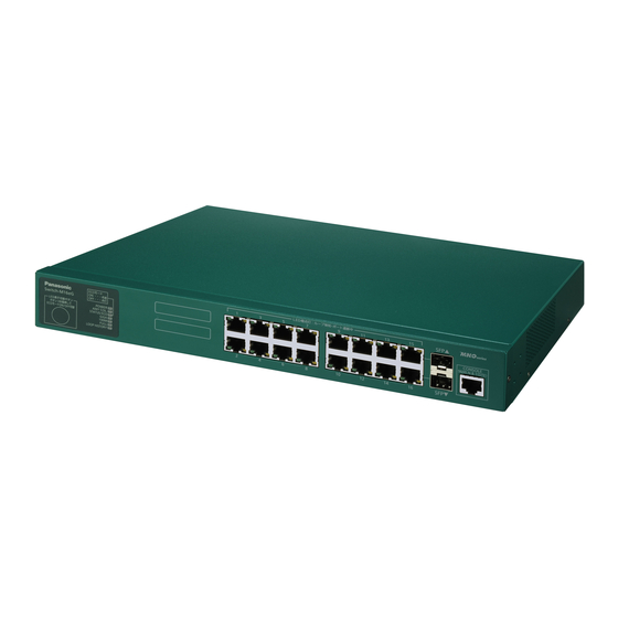
Switch-M16eG
Model Number: PN28160A
1
Advertisement
Table of Contents

Related Manuals for Panasonic PN28160A


Summary of Contents for Panasonic PN28160A
- Page 1 Switch-M16eG Operation Manual Menu Screens Model Number: PN28160A Thank you for purchasing our product. This manual provides important information about safe and proper operations of this Switching Hub. Please read the "Important Safety Instruction" on pages 2 to 3.
-
Page 2: Important Safety Instructions
Important Safety Instructions This chapter contains important safety instructions for preventing bodily injury and/or property damage. You are required to follow them. Severity of bodily injury and/or property damage, which could result from incorrect use of the Switching Hub, are explained below. WARNING This symbol indicates a potential hazard that could result in serious injury or death. - Page 3 WARNING Do not install this Switching Hub at the location with continuous vibration or strong shock, or at the unstable location. Deviation could lead to injury and/or equipment failure. Do not install any module other than the separately sold SFP module to SFP extension slot.
-
Page 4: Basic Instructions For The Use Of This Product
Basic Instructions for the Use of This Product For inspection and/or repair, consult the shop. Use commercial power supply from a wall socket, which is close and easily accessible to this Switching Hub. Unplug the power cord when installing or moving this Switching Hub. ... - Page 5 When stacking Switching Hubs, leave a minimum of 20 mm space between them. Panasonic will not be liable for any damage resulting from the operation not in accordance with this document or the loss of communications, which may or may not be caused by failure and/or malfunction of this product.
-
Page 6: Table Of Contents
Table of Contents Important Safety Instructions ..................2 Basic Instructions for the Use of This Product .............. 4 1. Product Outline....................8 1.1. Features....................... 8 1.2. Accessories ....................9 1.4. Part Names and Functions ................10 1.5. LED Behavior ....................11 1.5.1. - Page 7 4.6.8. Forwarding Database................62 4.6.9. Time Configuration ................. 67 4.6.10. ARP Table..................70 4.7. Advanced Switch Configuration ............... 72 4.7.1. VLAN Management ................. 73 4.7.2. Link Aggregation ..................83 4.7.3. Port Monitoring Configuration Menu ............85 4.7.4. Access Control Configuration Menu ............87 4.7.5 Quality of Service Configuration..............
-
Page 8: Product Outline
1. Product Outline Switch-M16eG is an all Giga bit Ethernet Switching Hub with management function having 14 ports of 10/100/1000BASE-T and two pairs of 10/100/1000BASE-T port and SFP extension slot, one of which is selectable. Has wire-speed Layer 2 switching function. ... -
Page 9: Accessories
Please be sure to confirm the content. Please contact our distributor if any of the contents are insufficient. Quantity Installation Guide (this document)…………………..……………………… 1 CD-ROM (PDF version of Operating Instructions)…………………..… 1 Mounting bracket (for 19-inch rack)………………………………………. 2 Screws (for 19-inch rack)……………………………………………………. 4 Screws (for fixing the main unit and the mounting bracket)………... -
Page 10: Part Names And Functions
Back panel Power code hook block Power port Serial number label MAC address label 10/100/1000BASE-T port SFP extension slot Front panel Magnified RJ45 console port Power LED Collision LED STATUS/ECO mode LED GIGA mode LED Speed mode LED Duplex mode LED LED DISPLAY CHANGE BUTTON LOOP HISTORY mode LED... -
Page 11: Led Behavior
1.4.1. LED Behavior at Start-up Upon turning this Switching Hub on, all LEDs tentatively light up. Then, the self-diagnosis of hardware is executed. Upon finishing the diagnosis, power LED and status/ECO mode LED light in solid green. Then, the Switching Hub starts working. 1.4.2. - Page 12 Port LED display mode LED In the status mode described later, port LED shows linkup and communication status. By pressing the LED display switch button in the front panel, the display mode of port LED can be changed as follows. Port LED display mode Description STATUS/ECO...
-
Page 13: Loop Detection Function
Port LED (right) Port LED (left) Fig. 1-4 Port LED 1.4.3. Loop detection function Turns on the port LED with an orange light when a loop occurs in the corresponding port. At this time, the relevant port automatically shuts down (default setting: 60 sec.) to prevent loop from occurring. -
Page 14: Led Display Change Button
1.5.1. Setting LED Base Mode You can select display of LEDs in this Switching Hub from two types: Status mode and Eco mode. The mode selected at system start-up is called the base mode. The base mode can be switched by keeping pressing the LED display switch button for more than 3 seconds. -
Page 15: Installation
2. Installation Switch-M16eG can be installed to a stainless steel product, a 19-inch rack, or on the wall. Take out the supplied 4 rubber feet (with built-in magnets), and place the Switching Hub upside down. Fix the 4 rubber feet firmly to the Switching Hub using 4 screws (for magnetic mount). -
Page 16: Mounting To 19-Inch Rack
Take out the supplied 2 mounting brackets (for 19-inch rack) and 8 screws (for fixing the main unit and the mounting bracket), and fix the brackets to the main unit by tightening screws into 4 holes located at the sides. Then, mount this Switching Hub firmly to the rack using the supplied 4 screws (for 19-inch rack) or screws furnished at the rack. -
Page 17: Connection
3. Connection Connection Cable Use a CAT5E or higher twisted pair cable with 8P8C RJ45 modular plug. Network Configuration 100 m or shorter 100 m 100 m or shorter or shorter Fig. 3-1 Example of Connection The length of the cable connecting this Switching Hub and a device must be 100 m or shorter. When a terminal or a LAN device with auto negotiation function is connected to this Switching Hub, the port is automatically configured at the highest performance mode. -
Page 18: Connection Using An Sfp Extension Slot
1000BASE-SX: 550 m or shorter / 1000BASE-LX: 10 km or shorter 100 m 100 m or shorter or shorter Fig. 3-2 Example of Optical Fiber Cable Connection Plugging an SFP module (optional) into an SFP extension slot enables an optical fiber connection. Connect this Switching Hub's TX port to the RX port of the connected device and this Switching Hub's RX port to the TX port of the connected device. -
Page 19: Connection To Power
Connect the supplied power code to the power port of this Switching Hub and connect the other end into an electric outlet. This Switching Hub operates at 100-240 V (50/60 Hz). This Switching Hub does not have a power ON/OFF switch. Plugging the power cord turns on this Switching Hub's power and the operation starts. -
Page 20: Configuration
4. Configuration Upon power on, this Switching Hub starts working as a switching hub. To use the SNMP management functionality or other unique functions, you need to configure the Switching Hub using a console port, Telnet, or SSH. In this chapter, the configuration of this Switching Hub is explained. Note: You need to configure an IP address to access this Switching Hub via Telnet or SSH. -
Page 21: Login
If this screen does not appear, press Enter key to refresh the display or confirm that there is no error in configuration of communication mode and others. ============================================================================== PN28160/PN28160A Local Management System Version x.x.x.xx MAC Address: xx:xx:xx:xx:xx:xx ============================================================================== Login Menu Login: Fig. - Page 22 Enter key. Then, you need to enter a password, as shown in Fig. 4-2-3. The Switching Hub's default password is the same as the login name ("manager"). Enter the password correctly and press the Enter key. ============================================================================== PN28160/PN28160A Local Management System Version x.x.x.xx MAC Address: xx:xx:xx:xx:xx:xx ============================================================================== Login Menu...
-
Page 23: Basic Operations On The Screen
The console screen of the Switching Hub is organized as follows: 1. Title 2. Previous menu name 3. Current menu name PN28160/PN28160A Local Management System Basic Switch Configuration -> System IP Configuration Menu MAC Address: xx:xx:xx:xx:xx:xx IP Address: 192.168.1.10 4. Configuration Subnet Mask: 255.255.255.0... - Page 24 Screen Description Title The title of this screen. Shows "Local Management System" while being accessed via console. Shows "Remote Management System" while being accessed via Telnet. Previous menu Shows the name of the previous menu. Pressing "Q," described later, name opens the menu screen shown in this field.
-
Page 25: Main Menu
To move to a sub-menu, enter a command letter. To return to the previous menu, enter the "Q" command. The second line from the top shows the current menu name. PN28160/PN28160A Local Management System Main Menu [G]eneral Information [B]asic Switch Configuration... - Page 26 Screen Description General Information Shows this Switching Hub's hardware, firmware information and address settings. Basic Switch Configures this Switching Hub's basic functions (such as IP address, SNMP and Configuration… port settings). Advanced Switch Configures this Switching Hub's advanced functions (such as VLAN, link aggregation, Configuration…...
-
Page 27: General Information Menu
On the Main Menu, pressing "G" opens the General Information Menu, as shown in Fig. 4-5-1. This screen shows this Switching Hub's basic information. You cannot edit shown information on this screen. PN28160/PN28160A Local Management System Main Menu -> General Information System up for:... - Page 28 Screen Description System up for Shows accumulated time since the Switching Hub boot-up. Boot Code Shows the version of Boot Code. Version Runtime Code Shows the version of Runtime Code. Version (Upgrading firmware version described in 4.9.1 is applicable to Runtime Code.) Hardware Shows the hardware information.
-
Page 29: Basic Switch Configuration
On the Main Menu, pressing "B" opens the Basic Switch Configuration Menu, as shown in Fig. 4-6-1. On this screen, you can configure settings of IP address, SMNP, port, MNO series power saving mode, spanning tree and access control. PN28160/PN28160A Local Management System Main Menu -> Basic Switch Configuration Menu System [A]dministration Configuration... - Page 30 Screen Description System Administration Configures the administrative information, such as Switching Hub name, location Configuration and contact information. System IP Configuration Configures the IP-address-related network information. SNMP Configuration Configures SNMP-related settings. Port Configuration Basic Configures PoE for each port. Port Configuration Extend Configures extended port settings, such as port name.
-
Page 31: System Administration Configuration
On the Basic Switch Configuration Menu, pressing "A" opens the System Administration Configuration Menu, as shown in Fig. 4-6-2. On this screen, you can set administrative information, such as device name. PN28160/PN28160A Local Management System Basic Switch Configuration -> System Admin. Configuration Menu Description: Switch-M16eG Object ID: 1.3.6.1.4.1.396.5.4.2.10... - Page 32 Available commands are listed below. Set/edit the system name. Press "N." The command prompt changes to "Enter system name>." Enter a Switching Hub name in 50 one-byte characters or less. Set/edit the installation location information. Press "L." The command prompt changes to "Enter system location>." Enter a Switching Hub location in 50 one-byte characters or less.
-
Page 33: System Ip Configuration
On the Basic Switch Configuration Menu, pressing "I" opens the System IP Configuration Menu, as shown in Fig. 4-6-3. On this screen, you can set IP-address-related settings for this Switching Hub. PN28160/PN28160A Local Management System Basic Switch Configuration -> System IP Configuration Menu MAC Address:... - Page 34 Available commands are listed below. Set/edit the IP address. Press "I." The command prompt changes to "Enter IP address>." Enter an IP address for the Switching Hub. Set/edit the subnet mask. Press "M." The command prompt changes to "Enter subnet mask>." Enter a subnet mask for the Switching Hub.
-
Page 35: Snmp Configuration
On the Basic Switch Configuration Menu, pressing "N" opens the SNMP Configuration Menu, as shown in Fig. 4-6-4. On this screen, you can configure the SNMP agent settings. PN28160/PN28160A Local Management System Basic Switch Configuration -> SNMP Configuration Menu SNMP [M]anagement Configuration... - Page 36 Available commands are listed below. Configure the SNMP manager settings. Press "M." The SNMP Management Configuration Menu opens. Configure the trap receiver settings. Press "T." The SNMP Trap Receiver Configuration Menu opens. Quit the SNMP Configuration Menu and return to the previous menu.
- Page 37 On the SNMP Configuration Menu, pressing "M" opens the SNMP Management Configuration Menu, as shown in Fig. 4-6-5. On this screen, you can configure the SNMP manager settings. PN28160/PN28160A Local Management System SNMP Configuration -> SNMP Management Configuration Menu SNMP Manager List:...
- Page 38 Available commands are listed below. Set the SNMP manager status. Press "S." The command prompt changes to "Enter manager entry number>." Enter an SNMP manager entry number you wish to configure. Then, the command prompt changes to "Enable or Disable SNMP manger (E/D)>."...
- Page 39 On the SNMP Configuration Menu, pressing "T" opens the SNMP Trap Receiver Configuration Menu, as shown in Fig. 4-6-6. On this screen, you can configure the SNMP trap receiver settings. PN28160/PN28160A Local Management System SNMP Configuration -> SNMP Trap Receiver Configuration Menu Trap Receiver List:...
- Page 40 Available commands are listed below. Enable/disable the trap receiver. Press "S." The command prompt changes to "Enter manager entry number>." Enter an entry number for the trap receiver you wish to configure. Then, the command prompt changes to "Enable or Disable Trap Receiver (E/D)>."...
- Page 41 On the SNMP Trap Receiver Configuration Menu, pressing "d" opens the Enable/Disable Individual Trap Menu, as shown in Fig. 4-6-7. On this screen, you can configure the trap sending settings. PN28160/PN28160A Local Management System SNMP Trap Receiver Configuration -> Enable/Disable Individual Trap Menu SNMP Authentication Failure :...
- Page 42 Available commands are listed below. Enable/disable the trap sending at an SNMP authentication failure. Press "A." The command prompt changes to "Enable or Disable SNMP Authentication trap (E/D)>." Press "E" to enable the trap sending. Press "D" to disable it. Enable/disable the trap sending at a login failure.
-
Page 43: Port Configuration Basic
On the Basic Switch Configuration Menu, pressing "p" opens the Port Configuration Menu, as shown in Fig. 4-6-8. On this screen, you can configure port status display settings and port settings. PN28160/PN28160A Local Management System Basic Switch Configuration -> Port Configuration Basic Menu Port Trunk... - Page 44 Screen Description Port Shows the port number. Trunk Shows the group number for a trunked port. Type Shows the port type. 100TX The port type is 10/100BASE-TX. 1000T The port type is 10/100/1000BASE-T. 1000X The port type is SFP port. Admin Shows the current port status.
- Page 45 Available commands are listed below. Show the next page. Press "N." The screen shows the next port. Show the previous page. Press "P." The screen shows the previous port. Enable/disable a port. Press "A." The command prompt changes to "Select port number to be changed>." Enter a port number you wish to change.
- Page 46 Enable/disable the AUTO-MDI function. Press "S." The command prompt changes to "Enter port number>." Enter a port number (from 1 to 16) you wish to change. Press "0" to change the settings of all ports at a time. Then, the command prompt changes to "Enable or Disable Auto-MDl for port # (E/D)>."...
-
Page 47: Port Configuration Extend
On the Basic Switch Configuration Menu, pressing "e" opens the Port Configuration Menu, as shown in Fig. 4-6-9. On this screen, you can configure port status display settings and port settings. PN28160/PN28160A Local Management System Basic Switch Configuration -> Port Configuration Extend Menu Port Trunk... - Page 48 Screen Description Port Shows the port number. Trunk Shows the group number for a trunked port. Type Shows the port type. 100TX The port type is 10/100BASE-TX. 1000T The port type is 10/100/1000BASE-T. 1000X The port type is SFP extension port. Link Shows the current link status.
- Page 49 Note: The screen shows the port status; however, the status is not automatically updated. To display the latest status, press any key.
-
Page 50: Port Configuration Power Saving
On the Basic Switch Configuration Menu, pressing "o" opens the Port Configuration Power Saving Menu, as shown in Fig. 4-6-10. On this screen, you can configure port status display and power saving mode. PN28160/PN28160A Local Management System Basic Switch Configuration -> Port Configuration Power Saving Menu Port Link Trunk... - Page 51 Screen Description Port Shows the port number. Link Shows the current link status. Link is established successfully. Down Link is not established. Trunk Shows the group number for a trunked port. Type Shows the port type. 100TX The port type is 10/100BASE-TX. 1000T The port type is 10/100/1000BASE-T.
-
Page 52: System Security Configuration
On the Basic Switch Configuration Menu, pressing "S" opens the System Security Configuration screen, as shown in Fig. 4-6-11. On this screen, you can configure the access control settings to this Switching Hub for configuration and management. PN28160/PN28160A Local Management System Basic Switch Configuration -> System Security Configuration Console UI Idle Timeout:... - Page 53 Access is enabled. Disabled Access is disabled. IP Setup Shows the access settings for the IP address configuration software, bundled with the Panasonic Interface: network cameras. The factory default setting is "Enabled." * For instructions, refer to Appendix Enabled: Access is enabled.
- Page 54 Press "A." The Telnet Access Limitation Menu opens. For configuration details, refer to the next section (4.6.7.a). Configures the access settings for the IP address configuration software, bundled with the Panasonic network cameras. Press "I." The command prompt changes to "Enable or Disable IP setup interface (E/D)>."...
- Page 55 On the System Security Configuration Menu, pressing "A" opens the Telnet Access Limitation screen, as shown in Fig. 4-6-12. In this screen, you can configure limitation of equipment accessing to this Switching Hub via Telnet. PN28160/PN28160A Local Management System System Security Configuration -> Telnet Access Limitation Menu Telnet Access Limitation :...
- Page 56 Available commands are listed below. Enable/Disable the access limitation from Telnet. Set the access limitation from Telnet to Enable. Set the access limitation from Telnet to Disable. Set an IP address to be permitted. Five ranges can be set up. Press "A."...
- Page 57 On the System Security Configuration Menu, pressing "R" opens the RADIUS Configuration screen, as shown in Fig. 4-6-13. On this screen, you can configure access setting to RADIUS server that is used in login authentication. PN28160/PN28160A Local Management System System Security Configuration -> RADIUS Configuration Menu NAS ID: Nas1...
- Page 58 Available commands are listed below. Set a NAS ID (NAS Identifier). Press "I." The command prompt changes to "Enter NAS ID>." Enter NAS ID within 16 one-byte characters. Set an IP address of RADIUS server. Press "A." The command prompt changes to "Enter IP Address for RADIUS server>." Enter an IP address.
- Page 59 Fig. 4-6-14. On this screen, you can configure the SSH server setting. This Switching Hub supports SSHv2 only. Use and connect a client supporting SSHV2. PN28160/PN28160A Local Management System Basic Switch Configuration -> SSH Server Configuration SSH UI Idle Timeout: 5 Min.
- Page 60 Available commands are listed below. Generate an SSH server key. Press "G" to generate an SSH server key. Configure the SSH access setting. Press "H." The command prompt changes to "Enable or Disable SSH server (E/D)>." Press "E" to enable the access. Press "D" to disable the access. Configure the idle timeout settings for automatically terminating an SSH-connected session if no input is made.
- Page 61 On the System Security Configuration, pressing "B" opens the LED Base Mode Configuration screen, as shown in Fig. 4-6-15. On this screen, you can configure the LED base mode setting. PN28160/PN28160A Local Management System System Security Configuration -> LED Base Mode Configuration System LED base-mode: Status Note: Save Configuration to Flash will be executed when LED Base Mode changed.
-
Page 62: Forwarding Database
Menu, as shown in Fig. 4-6-16. In this screen, a list of MAC address required for transferring packets that have been learned and recorded. Also, you can add or delete MAC address statically. PN28160/PN28160A Local Management System Basic Switch Configuration -> Forwarding Database Menu [S]tatic Address Table... - Page 63 On the Forwarding Database Information Menu, pressing "S" opens the Static Address Table Menu, as shown in Fig. 4-6-17. In this screen, you can add or delete a MAC address statically. PN28160/PN28160A Local Management System Forwarding Database Menu -> Static Address Table Menu MAC Address...
- Page 64 On the Forwarding Database Information Menu, pressing "A" opens the MAC Learning Menu, as shown in Fig. 4-6-18. On this screen, you can configure the MAC address auto-learning setting for each port and limit the number of MAC address auto-learning. PN28160/PN28160A Local Management System Forwarding Database Menu -> MAC Learning Menu Port...
- Page 65 Available commands are listed below. Show the next page. Press "N." The screen shows the next port. Show the previous page. Press "P." The screen shows the previous port. Switches the status of auto-learning. Press "S." The command prompt changes to "Select Port Number to be changed>." Enter a port number you wish to change the setting.
- Page 66 On the Forwarding Database Information Menu, pressing "M" opens the Display MAC Address by MAC screen, as shown in Fig. 4-6-19. In this screen, you can display all MAC address tables in this Switching Hub. PN28160/PN28160A Local Management System Forwarding Database Menu -> Display MAC Address by MAC Age-Out Time: 300 Sec.
-
Page 67: Time Configuration
On the Basic Switch Configuration Menu, pressing "T" opens the Time Configuration Menu, as shown in Fig. 4-6-20. In this screen, you can configure the time setting and time synchronization setting by SNTP. PN28160/PN28160A Local Management System Basic Switch Configuration -> Time Configuration Menu Time ( HH:MM:SS ) - Page 68 PN28160/PN28160A Local Management System Basic Switch Configuration -> Time Configuration Menu Time ( HH:MM:SS ) : 10:20:33 Date ( YYYY/MM/DD ) : 2009/04/01 Wednesday SNTP Server IP : 192.168.0.2 SNTP Polling Interval : 1440 Min Time Zone : (GMT+09:00) Osaka,Sapporo,Tokyo...
- Page 69 Available commands are listed below. Set the time of internal clock of this Switching Hub. Press "C." The command prompt changes to "Enter Date(Year) >" and enter a year. Then, the command prompt changes to "Enter Date(Month) >" and enter a month. Then, the command prompt changes to "Enter Date(Day) >"...
-
Page 70: Arp Table
On the Basic Switch Configuration Menu, pressing "R" opens the ARP Table screen, as shown in Fig. 4-6-22. In this screen, you can refer and configure ARP table. PN28160/PN28160A Local Management System Basic Switch Configuration -> ARP Table Sorting Method :... - Page 71 Available commands are listed below. Show the next page. Press "N." The screen shows the next page. Show the previous page. Press "P." The screen shows the previous page. Set the age-out time of ARP table. Press "T." The command prompt changes to "Enter ARP age timeout value >." Enter the age-out time of ARP table with a value of 30 to 86400 (seconds).
-
Page 72: Advanced Switch Configuration
Fig. 4-7-1. On this screen, you can configure settings of VLAN, link aggregation, port monitoring, access control, storm control, QoS, loop detection/shut-off, and port grouping functions. PN28160/PN28160A Local Management System Main Menu -> Advanced Switch Configuration Menu [V]LAN Management... -
Page 73: Vlan Management
4.7.1. VLAN Management 4.7.1.a. Features Corresponding to IEEE802.1Q compatible Tag VLAN, a frame can be sent with a VLAN tag (hereinafter referred to as just "tag"). Having two different parameters of VLAN ID and PVID, forwarding destination of an untagged ... - Page 74 On the Advanced Switch Configuration Menu, pressing "V" opens the VLAN Management Menu, as shown in Fig. 4-7-2. On this screen, you can configure VLAN-related settings. PN28160/PN28160A Local Management System Advanced Switch Configuration -> VLAN Management Menu Total VLANs : 1...
- Page 75 Screen Description Internet Shows the status of Internet Mansion mode. Mansion Enabled Internet Mansion mode is enabled. Disabled Internet Mansion mode is disabled. (Factory default setting) Uplink Indicates the uplink port when Internet Mansion mode is enabled. VLAN ID Shows the VLAN ID of VLAN. VLAN Name Shows the VLAN name being configured.
- Page 76 Press "I." The command prompt changes to "Enable or Disable Internet Mansion Function? (E/D)>." Press "E" to enable the function. Press "D" to disable it. If "E" is selected, the command prompt changes to "Uplink port?>." Enter a port number you wish to configure as an uplink port. This function enables to configure all settings needed for the Internet mansion environment.
- Page 77 4.7.1.c. VLAN Creation Menu On the VLAN Management Menu, pressing "C" opens the VLAN Creation Menu , as shown in Fig. 4-7-3. On this screen, you can create VLAN. PN28160/PN28160A Local Management System VLAN Management -> VLAN Creation Menu VLAN ID...
- Page 78 Available commands are listed below. Set a VLAN ID (VLAN Identifier). Press "S." The command prompt changes to "Enter VLAN ID>." Enter a VLAN ID. Set a name of VLAN. Press "N." The command prompt changes to "Enter VLAN name>." Enter a VLAN name within 30 one-byte characters.
- Page 79 On the VLAN Management Menu, pressing "o" and specifying target VLAN ID open the VLAN Modification Menu, as shown in Fig. 4-7-4. On this screen, you can modify VLAN-related setting information. PN28160/PN28160A Local Management System VLAN Management -> VLAN Modification Menu VLAN ID...
- Page 80 Available commands are listed below. Set a name of VLAN. Press "N." The command prompt changes to "Enter VLAN name>." Enter a VLAN name within 30 one-byte characters. Set a member of VLAN. Press "P." The command prompt changes to "Enter egress port number>." Enter a port number you wish to set.
- Page 81 On the VLAN Management Menu, pressing "S" opens the VLAN Port Configuration Menu, as shown in Fig. 4-7-5. In this screen, you can configure VLAN-related settings by port. PN28160/PN28160A Local Management System VLAN Management -> VLAN Port Configuration Menu Port PVID Acceptable Frame Type...
- Page 82 Available commands are listed below. Show the next page. Press "N." The screen shows the next page. Show the previous page. Press "P." The screen shows the previous page. Configure PVID settings. Press "V." The command prompt changes to "Enter port number>." Enter a port number you wish to configure.
-
Page 83: Link Aggregation
4.7.2. Link Aggregation 4.7.2.a. About Link aggregation Link aggregation is a function that is possible to increase redundancy of network paths and bandwidth between Switching Hubs by grouping multiple ports to a trunk for connection. In this Switching Hub, up to 8 ports can be assigned to 1 group, and 8 groups can be created. - Page 84 4.7.2.b. Link Aggregation Menu On the Advanced Switch Configuration Menu, pressing "L" opens the Trunk Configuration Menu, as shown in Fig. 4-7-6. On this screen, you can configure Link Aggregation settings. PN28160/PN28160A Local Management System Advanced Switch Configuration -> Link Aggregation Menu Group...
-
Page 85: Port Monitoring Configuration Menu
Switching Hub, you can monitor packets between other ports that are normally filtered and cannot be monitored. On this screen, you can configure port monitoring settings. PN28160/PN28160A Local Management System Advanced Switch Configuration -> Port Monitoring Configuration Menu... - Page 86 Screen Description Monitoring Port Shows the destination port number of data to be monitored. Be Monitored Port(s) Shows the target port number to be monitored. Direction Shows the communication direction of target packet to be monitored. Monitors a transmit packet. Monitors a receive packet.
-
Page 87: Access Control Configuration Menu
On the Advanced Switch Configuration Menu, pressing "A" opens the Access Control Configuration Menu, as shown in Fig. 4-7-8. On this screen, you can set Access Control. PN28160/PN28160A Local Management System Advanced Switch Configuration -> Access Control Configuration Menu [C]lassifier... - Page 88 4.7.4.a. Classifier Configuration Menu On the Access Control Configuration Menu, pressing "C" opens the Classifier Configuration Menu, as shown in Fig. 4-7-9. On this screen, you can set classifier. PN28160/PN28160A Local Management System Access Control Configuration -> Classifier Configuration Menu Multifield Classifier:...
- Page 89 Available commands are listed below. Show the next page. Press "N." The screen shows the next page. Show the previous page. Press "P." The screen shows the previous page. Create a classifier. Press "C." The Create Classifier Configuration Menu opens. For the Create Classifier Configuration Menu, refer to the next section (4.7.5.b).
- Page 90 4.7.4.b. Create Classifier Configuration Menu On the Classifier Configuration Menu, pressing "C" opens the Create Classifier Configuration Menu, as shown in Fig. 4-7-10. On this screen, you can create a classifier. PN28160/PN28160A Local Management System Classifier Configuration -> Create Classifier Configuration Menu Classifier Index...
- Page 91 Available commands are listed below. Set a classifier index. Press "C." The command prompt changes to "Enter Classifier Index>." Enter a classifier index with a value of 1 to 65535. Set the source MAC address to be filtered. Press "S." The command prompt changes to "Enter source MAC address>." Enter the source MAC address as xx:xx:xx:xx:xx:xx.
- Page 92 Press "Y." The command prompt changes to "Set TCP SYN flag (Y/N)>." Press "Y" for filter with a TCP SYN flag. Press "Y" for no filtering or to remove filter. If filtered, True is displayed. If not filtered, False is displayed. Apply the setting.
- Page 93 On the Classifier Configuration Menu, pressing "M" opens the More Classifier Information screen, as shown in Fig. 4-7-11 and Fig. 4-7-12. On this screen, you can refer to classifier information. PN28160/PN28160A Local Management System Access Control Configuration -> Classifier Configuration Menu...
- Page 94 PN28160/PN28160A Local Management System Access Control Configuration -> Classifier Configuration Menu Multifield Classifier: Total Entries : 1 Index 802.1p VLAN ID TCP(SYN) ICMPTP ----- ------ ------- -------- ------------------------------------------------- 1 Ignore 1 Ignore Ignore Press any key to continue... Fig. 4-7-12 Classifier Configuration Menu 2...
- Page 95 On the Classifier Configuration Menu, pressing "S" opens the Show Detailed Entries Information Menu, as shown in Fig. 4-7-13. On this screen, you can refer to detailed classifier information. Classifier needs to be created before reference. PN28160/PN28160A Local Management System Classifier Configuration -> Show Detailed Entry Information Menu Detailed Classifier Information :...
- Page 96 Screen Description Classifier Index Shows the classifier index. Source MAC Address Shows the source MAC address. Source Mask length Shows the length (bits) of source address mask. Destination MAC Address Shows the destination MAC address. Destination Mask length Shows the length (bits) of destination address mask. VLAN ID Shows the VLAN ID.
- Page 97 On the Access Control Configuration Menu, pressing "I" opens the In-Profile Action Configuration Menu, as shown in Fig. 4-7-14. On this screen, you can configure in-profile setting. PN28160/PN28160A Local Management System Access Control Configuration -> In-Profile Action Configuration Menu In-Profile Action:...
- Page 98 Available commands are listed below. Show the next page. Press "N." The screen shows the next page. Show the previous page. Press "P." The screen shows the previous page. Create in-profile. Press "C." The Create In-Profile Action Menu opens. Refer to the next section (4.7.4.f). Policed-DSCP Mark the DSCP value.
- Page 99 On the In-Profile Action Configuration screen, pressing "C" opens the Create In-Profile Action Menu, as shown in Fig. 4-7-15. On this screen, you can create in-profile action. PN28160/PN28160A Local Management System In-Profile Action Configuration -> Create In-Profile Action Menu Index...
- Page 100 Available commands are listed below. Set an in-profile index number. Press "I." The command prompt changes to "Enter in-profile action index>." Enter an index number with a value of 1 to 65535. Deny/permit packets. Press "D." The command prompt changes to "Select Deny/Permit (1-2)>." Press "1" to deny packets.
- Page 101 On the Access Control Configuration Menu, pressing "O" opens the Out-Profile Action Configuration Menu, as shown in Fig. 4-7-16. On this screen, you can configure out-profile setting. PN28160/PN28160A Local Management System Access Control Configuration -> Out-Profile Action Configuration Menu Out-Profile Action:...
- Page 102 Available commands are listed below. Show the next page. Press "N." The screen shows the next page. Show the previous page. Press "P." The screen shows the previous page. Create out-profile. Press "C." The Create Out-Profile Action Menu opens. Refer to the next section (4.7.4.h). Delete out-profile.
- Page 103 On the Out-Profile Action Configuration screen, pressing "C" opens the Create Out-Profile Action Menu, as shown in Fig. 4-7-17. On this screen, you can create out-profile action. PN28160/PN28160A Local Management System Out-Profile Action Configuration -> Create Out-Profile Action Menu Index...
- Page 104 Available commands are listed below. Set an out-profile index number. Press "I." The command prompt changes to "Enter Out-Profile action index>." Enter an index number with a value of 1 to 65535. Deny/permit packets. Press "D." The command prompt changes to "Select Deny/Permit (1-2)>." Press "1" to deny packets.
- Page 105 Control. When using both Access Control and Link Aggregation functions, assign a practical physical port number, not a logical port created in Link Aggregation. PN28160/PN28160A Local Management System Access Control Configuration -> Port List Configuration Menu Port List: Total Entries : 0...
- Page 106 Available commands are listed below. Show the next page. Press "N." The screen shows the next page. Show the previous page. Press "P." The screen shows the previous page. Create a port list. Press "C." The command prompt changes to "Enter port list index>." Enter an index number to be created.
- Page 107 On the Access Control Configuration Menu, pressing "P" opens the Policy Configuration Menu, as shown in Fig. 4-7-19. On this screen, you can configure the policy settings. PN28160/PN28160A Local Management System Access Control Configuration -> Policy Configuration Menu Policy : Total Entries : 0 Index Classifier Seq.
- Page 108 Available commands are listed below. Show the next page. Press "N." The screen shows the next page. Show the previous page. Press "P." The screen shows the previous page. Create a policy. Press "C." The Create Policy Configuration Menu opens. For the Create Policy Configuration Menu, refer to the next section (4.7.4.k).
- Page 109 4.7.4.k. Create Policy Configuration Menu On the Policy Configuration Menu, pressing "C" opens the Create Policy Configuration Menu, as shown in Fig. 4-7-20. On this screen, you can create a policy. PN28160/PN28160A Local Management System Policy Configuration -> Create Policy Configuration Menu Policy Index...
- Page 110 Available commands are listed below. Set a policy index number. Press "P." The command prompt changes to "Enter policy index>." Enter a policy index number. Set an index number of applicable classifier. Press "C." The command prompt changes to "Enter classifier index>." Enter an index number of applicable classifier.
-
Page 111: Quality Of Service Configuration
On the Advanced Switch Configuration Menu, pressing "S" opens the Quality of Service Configuration Menu, as shown in Fig. 4-7-21. You can configure the QoS (Quality of Service) setting of the Switching Hub. PN28160/PN28160A Local Management System Advanced Switch Configuration Menu -> Quality of Service Configuration Menu [T]raffic Class Configuration... - Page 112 On the Quality of Service Configuration Menu, pressing "T" opens the Traffic Class Configuration screen, as shown in Fig. 4-7-22. On this screen, you can configure the traffic class setting. PN28160/PN28160A Local Management System Quality of Service Configuration -> Traffic Class Configuration Menu...
- Page 113 On the Quality of Service Configuration Menu, pressing "C" opens the Egress Rate Limiting Configuration Menu, as shown in Fig. 4-7-23. On this screen, you can set bandwidth control. PN28160/PN28160A Local Management System Quality of Service Configuration -> Egress Rate Limiting Configuration Menu...
-
Page 114: Storm Control Configuration Menu
On the Advanced Switch Configuration Menu, pressing "o" opens the Storm Control Configuration Menu, as shown in Fig. 4-7-24. You can set the storm control for unknown unicast, broadcast, and multicast traffic. PN28160/PN28160A Local Management System Advanced Switch Configuration -> Storm Control Configuration Menu Port Storm Control Setting:... - Page 115 Available commands are listed below. Enable/disable the storm control for unknown unicast traffic. Press "D." The command prompt changes to "Enter port number>." Enter a port number to designate. Then, the command prompt changes to "Enable or Disable DLF storm control status>." Press "E" to enable the unknown unicast control.
-
Page 116: Loop Detection Configuration Menu
For network configuration, also refer to "Appendix D. Example of Network Configuration using Loop Detection/Shut-off Function and Its Precautions" in this operation manual. PN28160/PN28160A Local Management System Advanced Switch Configuration -> Loop Detection Configuration Menu Global Loop Detection Status: Enabled... - Page 117 Screen Description Global Loop Detection Shows the status of loop detection/shut-off function. Status Enabled The loop detection/shut-off function is enabled. (Factory default setting) Disabled The loop detection/shut-off function is disabled. Port Shows the port number. Trunk Shows the link aggregation group ID. Link Shows the state of linkup.
- Page 118 Available commands are listed below. Set the status of loop detection/shut-off function. Press "E." The command prompt changes to "Enable or Disable Loop Detection (E/D)>." Press "E" to enable the loop detection/shut-off function. Press "D" to disable it. Press "I." The Loop History Information screen opens. Set the status of loop detection/shut-off function of each port.
- Page 119 On the Loop Detection Configuration Menu, pressing "I" opens the Loop History Information screen, as shown in Fig. 4-7-26. On this screen, the date and time of detecting loop and the event information are listed. PN28160/PN28160A Local Management System Loop Detection Configuration Menu -> Loop History Information Entry Time(YYYY/MM/DD HH:MM:SS)
-
Page 120: Port Group Configuration Menu
4.7.8. Port Group Configuration Menu On the Advanced Switch Configuration Menu, pressing "P" opens the Port Group Configuration Menu, as shown in Fig. 4-7-28. On this screen, you can configure port grouping. If a port grouping is configured, ports designated as members of the port group can communicate only among member ports in the same group. - Page 121 PN28160/PN28160A Local Management System Advanced Switch Configuration -> Port Group Configuration Menu Total Groups : 0 Group ID Group Name Group Member -------- ---------------- --------------------------------- -------------------------------- <COMMAND> ----------------------------------- Enable/Disable Port [G]rouping [N]ext Page [C]reate Group [D]elete Group [P]revious Page [M]odify Group [Q]uit to previous menu Command>...
- Page 122 Available commands are listed below. Show the next page. Press "N." The screen shows the next page. Show the previous page. Press "P." The screen shows the previous page. Go to the screen for creating a port group. Press "C." The Port Group Create Menu opens. For details, refer to the next section (4.7.6.a). Delete a port group.
- Page 123 On the Port Group Management Menu, pressing "C" opens the Port Group Creation Menu, as shown in Fig. 4-7-29. On this screen, you can create a port group. PN28160/PN28160A Local Management System Port Group Configuration -> Port Group Creation Menu...
- Page 124 Available commands are listed below. Set a port group ID. Press "G." The command prompt changes to "Enter Port Group ID>." Enter a port group ID. Set a port group name. Press "N." The command prompt changes to "Enter Port Group name>." Enter a port group name in 16 one-byte characters or less.
- Page 125 On the Port Group Management Menu, pressing "o" and then specifying a port group ID open the Port Group Modification Menu, as shown in Fig. 4-7-30. On this screen, you can modify the port group setting. PN28160/PN28160A Local Management System Port Group Configuration -> Port Group Modification Menu Group ID...
- Page 126 Available commands are listed below. Set a port group name. Press "N." The command prompt changes to "Enter Port Group name>." Enter a port group name in 16 one-byte characters or less. Set a port group member. Press "P." The command prompt changes to "Enter egress port number>." Enter a port number you wish to set.
-
Page 127: Statistics
On the Main Menu, pressing "S" opens the Statistics Menu, as shown in Fig. 4-8-1. On this screen, you can confirm the statistics information of packets and thereby grasp the network status. PN28160/PN28160A Local Management System Main Menu -> Statistics Menu Port: Refresh: 300 Sec. - Page 128 Available commands are listed below. Show the values of the next port. Press "N." The screen shows the counter values of the next port. Disabled in Port 16. Show the values of the previous port. Press "P." The screen shows the counter values of the previous port. Disabled in Port 1. Switch a target port.
- Page 129 On this screen, you can display two types of values: Values accumulated since booting the Switching Hub (Fig. 4-8-1) and values accumulated since the counter reset (Fig. 4-8-2). An accumulated value since booting is retained even if the counter is reset. PN28160/PN28160A Local Management System Main Menu -> Statistics Menu Port: 1 Refresh: 300 Sec.
- Page 130 Screen Description Port Shows the port number. Refresh Shows the refresh interval of the screen. (Factory default setting: 300 seconds) Elapsed Time Since Shows the time elapsed since resetting counters. Reset Counter Name Shows each counter name. Total Shows each counter value. Avg./s Shows the average per second of each counter.
- Page 131 The counters are described below. Total RX Bytes Shows the number of bytes of all packets received. Total RX Pkts Shows the number of all packets received. Good Broadcast Shows the number of broadcast packets received. Good Multicast Shows the number of multicast packets received. CRC/Align Errors Shows the number of error packets that have a normal packet length (64 to 1518 bytes);...
-
Page 132: Switch Tools Configuration
Fig. 4-9-1. On this screen, you can configure and use additional functions of the Switching Hub, including firmware upgrade, upload/download of configuration, system reboot, and log viewing. PN28160/PN28160A Local Management System Main Menu -> Switch Tools Configuration [T]FTP Software Upgrade... -
Page 133: Tftp Software Upgrade
On the Switch Tools Configuration Menu, pressing "T" opens the TFTP Software Upgrade screen, as shown in Fig. 4-9-2. On this screen, you can upgrade the firmware version. PN28160/PN28160A Local Management System Switch Tools Configuration -> TFTP Software Upgrade Image Version: x.x.x.xx... - Page 134 Available commands are listed below. Set the IP address of the TFTP server providing the firmware to be used for update. Press "S." The command prompt changes to "Enter IP address of TFTP server>." Enter the IP address of the TFTP server. Set the file name of the firmware to be upgraded.
- Page 135 (To cancel the TFTP transfer process, press Ctrl+C during transfer.) When download is completed, the firmware is rewritten. After waiting for the time set by the Reboot Timer, rebooting is automatically executed. PN28160/PN28160A Local Management System Software Upgrade Menu -> Download Status TFTP Server IP: 192.168.1.10...
-
Page 136: Configuration File Upload/Download
Upload/Download Menu, as shown in Fig. 4-9-4. On this screen, you can upload/download the configuration information of this Switching Hub to/from a PC as a file. PN28160/PN28160A Local Management System Switch Tools Configuration -> Configuration File Upload/Download TFTP Server IP: 0.0.0.0... - Page 137 Available commands are listed below. Set the IP address of the TFTP server to upload/download the configuration information. Press "S." The command prompt changes to "Enter IP address of TFTP server>." Enter the IP address of the TFTP server. Set the file name of the configuration information to be uploaded/downloaded. Press "F."...
-
Page 138: System Reboot
On the Switch Tools Configuration Menu, pressing "R" opens the System Reboot Menu, as shown in Fig. 4-9-5. On this screen, you can reboot this Switching Hub. PN28160/PN28160A Local Management System Switch Tools Configuration -> System Reboot Menu Reboot Status:... - Page 139 Available commands are listed below. Set the reboot type to normal reboot or factory default. Press "O." The command prompt changes to "Select one option (N/F/I)>." Press "N" to set the type to normal reboot. Press "F" to return it to factory default. Press "I" to save only the IP address setting and return the other settings to factory default.
-
Page 140: Exception Handler
On the Switch Tools Configuration Menu, pressing "x" opens the Exception Handler screen, as shown in Fig. 4-9-6. On this screen, you can configure the exception handling operations. PN28160/PN28160A Local Management System Switch Tools Configuration -> Exception Handler Exception Handler:... -
Page 141: Ping Execution
On the Switch Tools Configuration Menu, pressing "P" opens the Ping Execution screen, as shown in Fig. 4-9-7. On this screen, you can execute the ping command from the Switching Hub to confirm communications with connected terminals and other devices. PN28160/PN28160A Local Management System Switch Tools Configuration -> Ping Execution Target IP Address: 0.0.0.0... - Page 142 Press "E" to execute ping. Press "C" to only clear the display. Cancel the ping command. Press "S" or "Ctrl+C" during the ping execution to cancel it. Return to the previous menu. PN28160/PN28160A Local Management System Switch Tools Configuration -> Ping Execution Target IP Address: 192.168.1.1...
-
Page 143: System Log
Fig. 4-9-9. This screen shows logs of events occurred to the Switching Hub. This allows you to grasp the events occurred to the Switching Hub and utilize them for network management. PN28160/PN28160A Local Management System Switch Tools Configuration -> System Log Menu... - Page 144 Screen Description Entry Shows the event number. Time Shows the time when the event occurred. If the time is not set, the accumulated running time since boot is shown. Event Shows the description of the event occurred to the Switching Hub. Available commands are listed below.
- Page 145 Indicates that port initialization has failed due to hardware error. Port-X link-down Indicates that Port X was linked down. info Port-X link-up Indicates that Port X was linked up. SNMP Not authorized!(IP: IP ADDRESS) Indicates that an unauthorized IP address has accessed SNMP. info System authentication failure.
- Page 146 Indicates that download of configuration file from TFTP server was successful. Configuration file upload Indicates that upload of configuration file to TFTP server was successful. Failure: Reload system default-config! Indicates that the system was booted with factory default setting due to failure in reading configuration.
- Page 147 Indicates that deletion of VLAN ID "X" has failed. VLAN X: interface list add failed. Indicates that addition of interface to VLAN ID "X" has failed.
-
Page 148: Watch Dog Timer Menu
On the Switch Tools Configuration Menu, pressing "W" opens the Watch Dog Timer Menu, as shown in Fig. 4-9-10. On this screen, you can enable/disable the Watch Dog Timer function. PN28160/PN28160A Local Management System Switch Tools Configuration -> Watch Dog Timer Menu Watch Dog Timer: Disabled -------------------------------- <COMMAND>... -
Page 149: Save Configuration To Flash
Press "Y" to save the configuration. Press "N" to cancel it. If you don't save the configuration on this screen, it will be deleted when the system is rebooted or turned off. PN28160/PN28160A Local Management System Main Menu -> Save Configuration to Flash Save current configuration? (Y/N)>... - Page 150 PN28160/PN28160A Local Management System Main Menu -> Save Configuration to Flash Saving configuration to flash is successful, press any key to continue... Fig. 4-10-2 Saving Configuration to Flash screen: Completion of save...
-
Page 151: Command Line Interface (Cli)
On the Main Menu, pressing "C" opens the screen shown in Fig. 4-11-1. On this screen, you can use the command line for configuration instead of the menu screen. For configuration procedure, refer to the separate volume "Operation Manual (CLI)." Enter "logout"... -
Page 152: Logout
If you access from the console port, pressing "Q" on the Main Menu opens the login screen shown in Fig. 4-2-1. If you access using Telnet, pressing "Q" terminates the connection. To login again, follow the login procedures shown in the section 4.2. You are automatically logged out after a specified timeout period. -
Page 153: Appendix A. Specifications
Appendix A. Specifications Interface - Twisted-pair port 1 - 14 (RJ45 connector) Standards IEEE 802.3 10BASE-T IEEE 802.3u 100BASE-TX IEEE 802.3ab 1000BASE-T - SFP extension slot 15 and 16 (*Select either of RF45 or SFP for use) Standards IEEE 802.3z ... - Page 154 Power supply specifications - Power supply AC 100-240 V, 50/60 Hz, 0.8 A - Power consumption Normally, max. 14.5 W, min. 5.4 W Environment specifications - Operating temperature 0 – 50C - Operating humidity 20 – 80% RH (no condensation) - Storage temperature -20 –...
-
Page 155: Appendix B. Procedures For Console Port Connection Using Windows Hyperterminal
Appendix B. Procedures for Console Port Connection using Windows HyperTerminal Connect a Windows-based PC to this Switching Hub with a console cable and follow the procedures shown below to activate HyperTerminal. (If your PC is using Windows Vista or later, you need to install a terminal emulator first.) (1) On Windows, click Start on Task Bar ... -
Page 156: Appendix C. Easy Ip Address Setup Function
* You can check the current settings because the list is displayed even after the time limit elapses. - The following function of the software of Panasonic System Networks Co., Ltd. cannot be used. - Auto setup function... -
Page 157: Precautions
Appendix D. Example of Network Configuration using Loop Detection Function and Its Precautions Example of configuration using loop detection function By using the loop detection function, you can prevent a loop failure that is likely to be caused in a downstream Switching Hub that the user directly uses. In addition, if a downstream Switching Hub is connected with a device, such as a hub without loop detection function, and a loop failure occurs under the device, the downstream Switching Hub shuts down the corresponding port to prevent the failure from extending to the entire... - Page 158 Precautions in using loop detection function – Disable loop detection at upstream port(s) If a network is consisted of only Switching Hub equipped with loop detection function, an upstream Switching Hub may detect on ahead and block a loop occurred in a downstream Switching Hub.
-
Page 159: Mib List
Appendix E. MIB List The MIB list of this Switching Hub is as follows. <port_num> is a port number. <ip_address> is an IP address. 1.1. system group MIB object Access Identifier Remarks sysDescr sysDescr.0 sysObjectID sysObjectID.0 sysUpTime sysUpTimeInstance.0 sysContact sysContact.0 sysName sysName.0 sysLocation... - Page 160 ifOutQLen ifOutQLen.<port_num> ifSpecific ifSpecific.<port_num> 1.3. IP group MIB object Access Identifier ipForwarding ipForwarding.0 ipDefaultTTL ipDefaultTTL.0 ipInReceives ipInReceives.0 ipInHdrErrors ipInHdrErrors.0 ipInAddrErrors ipInAddrErrors.0 ipInUnknownProtos ipInUnknownProtos.0 ipInDiscards ipInDiscards.0 ipInDelivers ipInDelivers.0 ipOutRequests ipOutRequests.0 ipOutDiscards ipOutDiscards.0 ipOutNoRoutes ipOutNoRoutes.0 ipReasmTomeout ipReasmTomeout .0 ipReasmReqds ipReasmReqds.0 ipReasmOKs ipReasmOKs.0 ipReasmFails ipReasmFails.0 ipFragOKs...
- Page 161 tcpOutRsts tcpOutRsts.0 tcpConnState tcpConnLocalAddress tcpConnLocalPort tcpConnRemAddress tcpConnRemPort 1.5. UDP group MIB object Access Identifier udpInDatagrams udpInDatagrams.0 udpNoPorts udpNoPorts.0 udpInErrors udpInErrors.0 udpOutDatagrams udpOutDatagrams.0 udpLocalAddress udpLocalPort 1.6. SNMP group MIB object Access Identifier snmpInPkts snmpInPkts.0 snmpOutPkts snmpOutPkts.0 snmpInBadVersions snmpInBadVersions.0 snmpInASNParseErrs snmpInASNParseErrs.0 snmpInTotalReqVars snmpInTotalReqVars.0 snmpInTotalSetVars snmpInTotalSetVars.0...
- Page 162 dot1dTpFdbStatus dot1dTpPort dot1dTpPort.<port_num> dot1dTpPortMaxInfo dot1dTpPortMaxInfo.<port_num> dot1dTpPortInFrames dot1dTpPortInFrames.<port_num> dot1dTpPortOutFrames dot1dTpPortOutFrames.<port_num> dot1dTpPortInDiscards dot1dTpPortInDiscards.<port_num> 2.1. Supporting trap Trap description Access Identifier Linku Up/Down Login Failure Authentication Failure ObjectID: mnoLoopDetection 1.3.6.1.4.1.396.5. 5.2.1 ObjectID: mnoLoopRecovery 1.3.6.1.4.1.396.5. 5.2.2...
-
Page 163: Troubleshooting
Troubleshooting If you find any problem, please take the following steps to check. 1. LED indicators * The POWER LED is not lit. - Is the power cord connected? Please confirm that the power cord is securely connected to the power port. * The port LED (left) is not lit in Status mode. -
Page 164: After-Sales Service
After-sales Service 1. Warranty card A warranty card is included in the operating instructions (paper) provided with this Switching Hub. Be sure to confirm that the date of purchase, shop (company) name, etc., have been entered in the warranty card and then receive it from the shop. Keep it in a safe place. - Page 165 Tel: (* You can check the version on the screen described in section 4.5 of this document.) © Panasonic Eco Solutions Networks Co., Ltd. 2013 Panasonic Eco Solutions Networks Co., Ltd. 2-12-7, Higashi-Shimbashi, Minato-ku, Tokyo Japan, 105-0021 URL: http://panasonic.co.jp/es/pesnw/english/...
Need help?
Do you have a question about the PN28160A and is the answer not in the manual?
Questions and answers