Table of Contents
Advertisement
Quick Links
Operation
Manual
for Menu Interface
Thank you for purchasing our product.
This manual provides important information about safe and proper operations
of this switch.
Please read the "Important Safety Instructions" on pages 3 to 6.
If you disassemble this switch for any reason, damage is not covered by war-
ranty.
Switch-M16eGLPWR+
Model Number: PN28168
Advertisement
Table of Contents

Related Manuals for Panasonic PN28168


Summary of Contents for Panasonic PN28168
- Page 1 Switch-M16eGLPWR+ Operation Manual Model Number: PN28168 for Menu Interface Thank you for purchasing our product. This manual provides important information about safe and proper operations of this switch. Please read the "Important Safety Instructions" on pages 3 to 6.
- Page 2 The target model for this Operation Manual is as follows. Model name Model number Firmware version Switch-M16eGLPWR+ PN28168-ID 2.0.0.00 and higher PN28168-TH PN28168-MY PN28168-SG...
-
Page 3: Important Safety Instructions
Important Safety Instructions Please Follow the Instructions This chapter contains important safety instructions for preventing bodily injury and/or property damage. You are required to follow them. ■Severity of bodily injury and/or property damage, which could result from incor- rect use of the Switching Hub, are explained below. This symbol indicates a potential hazard that could result in serious injury or death. - Page 4 ●Do not insert any modules other than the optional SFP modules (PN54021K/PN54023K) into the SFP extension slot. Deviation could lead to fire, electric shock, and/or equipment failure. For the latest information about compatible SFP extension modules, check our website. ●Do not please this Switching Hub in harsh environment (such as near water, high humid, and/or high dust).
- Page 5 ●Use the bundled power cord (AC 100 - 240V specifications). Deviation could lead to electric shock, malfunction, and/or equipment failure.The warranty does not cover any problems resulting from the use of any power cord other than the one supplied. ●Unplug the power cord in case of equipment failure. Deviation such as keeping connected for a long time could lead to fire.
- Page 6 Important Notice for Measures against Failures Caused by Lightning Strikes ●When connecting devices (especially outdoor devices) prone to lightning strikes, such as network cameras or wireless access points, to a twisted pair port of this Switching Hub, overcurrent and/or overvoltage caused by lightning may affect this Switching Hub through a twisted pair cable, causing equipment failure.
-
Page 7: Basic Instructions For The Use Of This Product
Basic Instructions for the Use of This Product ●For inspection and/or repair, consult the retailer. ●Use commercial power supply from a wall socket, which is close and easily accessible to this Switching Hub. ●Unplug the power cord when installing or moving this Switching Hub. ●Unplug the power cord when cleaning this Switching Hub. - Page 8 SFP extension slot. For the latest information about compatible SFP extension modules, check our website. 1. Panasonic will not be liable for any damage resulting from the operation not in accordance with this operation manual, or loss of communications, which may or may not be caused by failure and/or malfunction of this device.
-
Page 9: Table Of Contents
Table of Contents Important Safety Instructions .......................... 3 ● Basic Instructions for the Use of This Product ..........7 Product Outline ..................12 1.1. Features ....................12 1.2. Accessories ..................13 1.3. Optional Accessories ................14 1.4. Part Names and Functions ..............15 1.5. - Page 10 4.5.8.a. Addition or Deletion of MAC Address ........69 4.5.8.b. MAC Address Learning Mode Configuration ......71 4.5.8.c. Display of MAC Address Table by Port ........73 4.5.8.d. Display of All MAC Addresses ..........74 4.5.8.e. Display of MAC Address Table by VLAN ........ 75 4.5.9.
- Page 11 4.6.10.b. RRP Domain Modification Menu ......... 154 4.6.10.c. RRP Domain information Menu .......... 156 4.6.11. Loop Detection Configuration Menu .......... 158 4.6.11.a. Loop History Information ............ 160 4.6.12. Digital Diagnostic Monitoring Menu ........... 161 4.7. Statistics ..................... 163 4.8. Switch Tools Configuration ..............167 4.8.1.
-
Page 12: Product Outline
1. Product Outline Switch-M16eGLPWR+ is an Ethernet Switching Hub with management function having 16 ports of 10/100/1000BASE-T and two pairs of 10/100/1000BASE-T ports and SFP extension slot, one of which is selectable. Ports 1 to 16 support IEEE802.3at PoE power supply function. 1.1. -
Page 13: Accessories
1.2. Accessories Please be sure to confirm the contents. Please contact our distributor if any of the contents are insufficient. Quantity * Switch-M16eGLPWR+................1 * Installation Guide ..................1 * CD-ROM (PDF version of Operating Instructions) ........1 * Rubber foot ..................... 4 * Mounting bracket (for 19-inch rack) ............ -
Page 14: Optional Accessories
1.3. Optional Accessories * PN54021K SFP-1000SX 1000BASE-SX SFP Module * PN54023K SFP-1000LX 1000BASE-LX SFP Module... -
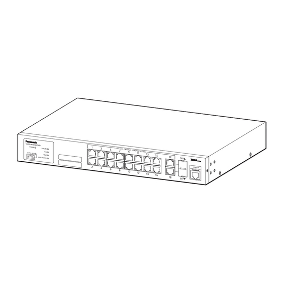
Page 15: Part Names And Functions
1.4. Part Names and Functions Figure 1-1 Part names... - Page 16 ● Power port Connect the supplied power cord to this point and connect the other end into an electric outlet. ● Power cord hook block Hooking the supplied power cord on the block makes the cord less likely to be unplugged from the power port.
-
Page 17: Led Behavior
1.5. LED Behavior 1.5.1. LED Behavior at Starting-up When power is supplied, all the LEDs are turned ON. Then, self-diagnosis of hardware is executed. On completion of self-diagnosis, POWER LED (Power), STATUS/ECO LED (Status/ ECO mode), FAN LED (Fan sensor), TEMP LED (Temperature sensor) light in green, and the Switching Hub starts operation as a Switching Hub. -
Page 18: Led Behavior While Operating
1.5.2. LED Behavior while Operating This Switching Hub has a set of LEDs for each port. These LEDs indicate the opera- tion status of each port. ● System LED Behavior Description Power LED Green Light Power is On (POWER) Power is Off Status/ECO mode LED Green Light Operating in the Status mode. - Page 19 ● Port LED Port LED Display mode Behavior Description Left STATUS/ECO Green Light Link is established at 10/100/1000 Mbps. (when the LOOP Green Blink Transmitting and receiving data. HISTORY LED is Orange Light Shut off by the loop detection/shutoff function. off) No device connected, or set to ECO mode.
-
Page 20: Loop Detection And Blocking Function
1.5.3. Loop Detection and Blocking Function When a port causes a loop, the corresponding port LED (Left) lights up in orange. In this case, the port is automatically blocked (Default setting: 60 seconds) to pre- vent a loop. If the loop is not recovered, the port will be blocked again. Recover the loop while the port is blocked. -
Page 21: Operation Overview Of Poe Power Supply Function
1.5.4. Operation Overview of PoE Power Supply Func- tion Ports 1-16 can support IEEE802.3at PoE power supply. The Switching Hub can sup- ply power up to 30 W per port, and up to 185 W in total. ● Power supply operation when the PoE limit LED is blinking orange (the whole unit is overloaded) When the whole unit is overloaded because power request exceeds the limit, you can verify a port that stopped supplying power by the corresponding port LED... -
Page 22: Installation
2. Installation Switch-M16eGLPWR+ can be installed in a 19-inch rack. 2.1. Installing in Rack Use the supplied two 19-inch rack mount brackets and eight screws (for fixing the mount brackets to the Switching Hub) to fix the mount brackets to the four holes on each side of the Switching Hub. -
Page 23: Connection
3. Connection 3.1. Connecting a Twisted Pair Port ● Connection Cable Use a CAT5e-compliant straight cable (twisted pair) with 8P8C RJ45 modular plugs when connecting. ● Network Configuration 100 m or shorter 100 m or shorter 100 m or shorter Figure 3-1 Connection configuration example The length of the cable connecting this Switching Hub and a device must be 100m or shorter. -
Page 24: Connecting An Sfp Extension Slot
3.2. Connecting an SFP Extension Slot 1000BASE-SX: 550 m or shorter, 1000BASE-LX: 10 km or shorter 100 m or shorter 100 m or shorter Figure 3-2 Optical fiber cable connection example Plugging an SFP module (optional) into an SFP extension slot enables an optical fiber connection. -
Page 25: Connecting To Power
3.3. Connecting to Power Connect the bundled power cord to the power port of this Switching Hub and con- nect the power plug into an electric outlet. The Switching Hub operates on AC 100-240 V (50/60 Hz). This Switching Hub does not have a power switch. Plugging the power cord turns on this Switching Hub's power and it starts operating. -
Page 26: Configuration
4. Configuration Upon power on, this Switching Hub starts working as a normal Switching Hub. To use the SNMP functions and other functions, you need to configure the Switching Hub by using the console, Telnet, SSH, or WEB control screen. In this chapter, the configuration of this Switching Hub is explained. -
Page 27: Login
If you access the Switching Hub via console, the screen displays as shown in Figure 4-1. If no similar window is displayed, make sure the transmission mode of console is correct or hit the enter key. ============================================================================== PN28168 Local Management System Version x.x.x.xx MAC Address: xx:xx:xx:xx:xx:xx ============================================================================== Login Menu Login: Figure 4-1 Login screen (Console) If you access the Switching Hub via Telnet or SSH, the screen displays "Remote... - Page 28 Return key. Then, you need to enter a password, as Figure 4-3 displays. The Switching Hub's default password is the same as the login name ("manager"). Enter the password correctly and press the Return key. ============================================================================== PN28168 Local Management System Version x.x.x.xx MAC Address: xx:xx:xx:xx:xx:xx ============================================================================== Login Menu...
-
Page 29: Basic Operations On The Screen
4.2. Basic Operations on the Screen The console screen of this Switching Hub is organized as follows: 1. Title 2. parent menu name 3. Current menu name PN28168 Local Management System Basic Switch Configuration -> System Admin. Configuration Menu Description: Switch-M16eGLPWR+ Object ID: 1.3.6.1.4.1.396.5.4.2.27 4. - Page 30 Screen Description Title The title of this screen. Displays "Local Management System" while being accessed via console. Displays "Remote Manage- ment System" while being accessed via Telnet or SSH. Previous menu name Displays the name of the parent menu. Entering the "Q" com- mand opens the parent menu screen.
-
Page 31: Main Menu
To move to a sub-menu, enter a command letter. To return to the previous menu, press the "Q" command. The sec- ond line from the top displays the current menu name. PN28168 Local Management System Main Menu [G]eneral Information [B]asic Switch Configuration... -
Page 32: General Information Menu
On the Main Menu, pressing "G" opens the General Information Menu screen, as shown in Fig. 4-6. This screen displays this Switching Hub's basic information. You cannot edit shown information on this screen. PN28168 Local Management System Main Menu -> General Information System up for: 000day(s), 00hr(s), 00min(s), 00sec(s) Boot / Runtime Code Version: x.x.x.xx / x.x.x.xx... - Page 33 Screen Description System up for Displays the cumulative time since the power on of this Switching Hub. Boot / Runtime Displays this Switching Hub's firmware version. Code Version The left side displays the Boot Code, and the right side displays the Runtime Code.
-
Page 34: Basic Switch Configuration
On the Main Menu, pressing "B" opens the Basic Switch Configuration Menu screen, as shown in Fig. 4-7. On this screen, you can configure the basic configura- tion settings, such as IP address, SNMP, and ports. PN28168 Local Management System Main Menu -> Basic Switch Configuration Menu System [A]dministration Configuration... - Page 35 Screen Description System Administration Configura- Configures the management information settings, such as tion Switching Hub name, place, and contact used for SNMP. System IP Configuration Configures the IP-address-related network information. SNMP Configuration Configures the SNMP-related settings. Port Configuration Basic Configure the basic settings for each port. Port Configuration Extend Configures the extended port settings, such as port name.
-
Page 36: System Administration Configuration
On the Basic Switch Configuration Menu, pressing "A" opens the System Adminis- tration Configuration Menu screen, as shown in Fig. 4-8. On this screen, you can set administrative information, such as device name. PN28168 Local Management System Basic Switch Configuration -> System Admin. Configuration Menu Description: Switch-M16eGLPWR+ Object ID: 1.3.6.1.4.1.396.5.4.2.27... - Page 37 Screen Description Description Displays the system information. This item is not editable. Object ID Displays the ID, corresponding to MIB. This item is not editable. Name Displays the system name. The factory default setting is blank. Location Displays the device installation location. The factory default setting is blank. Contact Displays the contact information.
-
Page 38: System Ip Address Configuration
On the Basic Switch Configuration Menu, pressing "I" opens the System IP Config- uration Menu screen, as shown in Fig. 4-9. On this screen, you can set IP-address- related settings for this Switching Hub. PN28168 Local Management System Basic Switch Configuration -> System IP Configuration Menu MAC Address:... - Page 39 Available commands are listed below. Set/edit the IP address. Press "I." The command prompt changes to "Enter IP address>." Enter the IP address for the Switching Hub. Set/edit the subnet mask. Press "M." The command prompt changes to "Enter subnet mask>." Enter the subnet mask for the Switching Hub.
-
Page 40: Snmp Configuration
On the Basic Switch Configuration Menu, pressing "N" opens the SNMP Configura- tion Menu screen, as shown in Fig. 4-10. On this screen, you can configure the SNMP agent settings. PN28168 Local Management System Basic Switch Configuration -> SNMP Configuration Menu SNMP [M]anagement Configuration... -
Page 41: Snmp Management Configuration
On the SNMP Configuration Menu, pressing "M" opens the SNMP Management Configuration Menu screen, as shown in Fig. 4-11. On this screen, you can config- ure the SNMP manager settings. PN28168 Local Management System SNMP Configuration -> SNMP Management Configuration Menu SNMP Manager List:... - Page 42 Available commands are listed below. Set the SNMP manager status. 1. Press "S." The command prompt changes to "Enter manager entry number>." Enter the entry number for the SNMP manager you wish to configure. 2. Then, the command prompt changes to "Enable or Disable SNMP manger (E/D)>." Press "E"...
-
Page 43: Snmp Trap Receiver Configuration
On the SNMP Configuration Menu, pressing "T" opens the SNMP Trap Receiver Configuration Menu screen, as shown in Fig. 4-12. On this screen, you can config- ure the SNMP Trap settings. PN28168 Local Management System SNMP Configuration -> SNMP Trap Receiver Configuration Menu Trap Receiver List:... - Page 44 Available commands are listed below. Enable/disable the trap receiver. 1. Press "S." The command prompt changes to "Enter manager entry number>." Enter the entry number for the trap receiver you wish to configure. 2. Then, the command prompt changes to "Enable or Disable Trap Receiver (E/D)>." Press "E"...
-
Page 45: Enable/Disable Individual Trap Menu
On the SNMP Trap Receiver Configuration Menu, pressing "D" opens the Enable/ Disable Individual Trap Menu screen, as shown in Fig. 4-13. On this screen, you can set the trap sending settings. PN28168 Local Management System SNMP Trap Receiver Configuration -> Enable/Disable Individual Trap Menu SNMP Authentication Failure :... - Page 46 Screen Description SNMP Authenti- Displays the trap sending settings for an SNMP authentication failure. cation Failure: Enabled Enables the trap sending. Disabled Disables the trap sending. (Factory default setting) Enabled Link Displays the port number to which a trap is sent, when its link status changes. Up/Down Port: All ports are assigned in factory default setting.
- Page 47 Available commands are listed below. Enable/disable the trap sending when an SNMP authentication fails. Press "A." The command prompt changes to "Enable or Disable SNMP Authentication trap(E/D)>." Press "E" to enable the trap sending. Press "D" to disable it. Add a port for which the trap is sent when its link status changes. Press "P."...
-
Page 48: Port Configuration Basic
On the Basic Switch Configuration Menu, pressing "P" opens the Port Configura- tion Basic Menu screen, as shown in Fig. 4-14. On this screen, you can display port status and configure port settings. PN28168 Local Management System Basic Switch Configuration -> Port Configuration Basic Menu Port Trunk... - Page 49 Screen Description Port Displays the port number. Trunk Displays the group number for a trunked port. Type Displays the port type. 100TX The port type is 10/100BASE-TX. 1000T The port type is 10/100/1000BASE-T. 1000X The port type is 1000BASE-X (SFP port). Admin Displays the current port status.
- Page 50 Available commands are listed below. Display the next page. Press "N" to display the next page. Display the previous page. Press "P" to display the previous page. Enable/disable a port. 1. Press "A." The command prompt changes to "Select port number to be changed>." Enter a port number you wish to configure.
-
Page 51: Port Configuration Extend
On the Basic Switch Configuration Menu, pressing "E" opens the Port Configura- tion Extend Menu screen, as shown in Fig. 4-15. On this screen, you can display port status and configure extended port settings. PN28168 Local Management System Basic Switch Configuration -> Port Configuration Extend Menu Global Jumbo Status: Disabled... - Page 52 Available commands are listed below. Display the next page. Press "N" to display the next page. Display the previous page. Press "P" to display the previous page. Assign a name to each port. 1. Press "A." The command prompt changes to "Select port number to be changed>." Enter a port number you wish to configure.
-
Page 53: Port Configuration Power Saving
On the Basic Switch Configuration Menu, pressing "o" opens the Port Configura- tion Power Saving screen, as shown in Fig. 4-16. On this screen, you can display port status and configure various power saving mode settings. PN28168 Local Management System Basic Switch Configuration -> Port Configuration Power Saving Menu Port... - Page 54 Mode Displays the communication speed and full-duplex/half-duplex settings. For all ports, "Auto" is the factory default setting. Auto Auto negotiation mode 100-FDx(100F) 100 Mbps full-duplex 100-HDx(100H) 100 Mbps half-duplex 10-FDx(10F) 10 Mbps full-duplex 10-HDx(10H) 10 Mbps half-duplex Power-Saving Displays the status of the MNO series power saving mode. For all ports, "Half"...
-
Page 55: System Security Configuration
Configuration screen, as shown in Fig. 4-17. On this screen, you can configure the various settings for accessing this Switching Hub for configuration and manage- ment. PN28168 Local Management System Basic Switch Configuration -> System Security Configuration Console UI Idle Timeout: 5 Min. - Page 56 Screen Description Console UI Idle Displays the idle timeout settings (in minutes) for terminating a console-con- Time Out: nected session if no input is made. The factory default setting is 5 minutes. Telnet UI Idle Displays the idle timeout settings (in minutes) for terminating a Telnet-connected Time Out: session if no input is made.
- Page 57 Available commands are listed below. Configure the idle timeout settings for automatically terminating a console-connected session if no input is made. Press "C." The command prompt changes to "Enter console idle timeout>." Enter a value from 0 to 60 (minutes). Entering "0" disables the automatic termination. Configure the idle timeout settings for automatically terminating a Telnet-connected session if no input is made.
- Page 58 Configure the SSH server settings. Press "H" to move to the SSH Server Configuration page. For configuration details, refer to the next section (4.5.7.d). Configure the location to check the login username and password. 1. Press "O." The command prompt changes to "Enter manager entry number>." Press "1" to change the first location to check.
-
Page 59: Telnet Access Limitation Configuration
Limitation screen, as shown in Fig. 4-18. On this screen, you can configure limita- tion of equipment accessing to this Switching Hub via Telnet. PN28168 Local Management System System Security Configuration -> Telnet Access Limitation Menu Telnet Access Limitation :... - Page 60 Delete a range of IP address that has been set up. Press "D." The command prompt changes to "Enter IP address entry number>." Enter an IP address entry number you wish to delete. M Change a range of IP address that has been set up. 1.
-
Page 61: Radius Configuration
On the System Security Configuration Menu, pressing "R" opens the RADIUS Con- figuration Page screen, as shown in Fig. 4-19. On this screen, you can configure access to the RADIUS server that is used in IEEE802.1X authentication. PN28168 Local Management System System Security Configuration -> RADIUS Configuration Menu NAS ID: Nas1... - Page 62 Set the common key of the RADIUS server. Press "C." The command prompt changes to "Enter secret string for server>." Enter the secret string in 20 characters or less. Set the response time until the RADIUS server responds to the authentication request. Press "R."...
-
Page 63: Syslog Transmission Configuration
Configuration Page screen, as shown in Fig. 4-20. On this screen, you can configure the settings of the Syslog server to which a system log is sent. PN28168 Local Management System System Security Configuration -> Syslog Transmission Configuration Menu... - Page 64 Set Facility. 1. Press "F." The command prompt changes to "Enter manager entry number>." Enter a num- ber you wish to set. 2. Then, the command prompt changes to "Enter Server Facility>." Enter a value of 0 to 7 (Local0 to Local7). Set the IP address of the Syslog server.
-
Page 65: Ssh Server Configuration
Configuration screen, as shown in Fig. 4-21. On this screen, you can configure the SSH server settings. This Switching Hub only supports SSHv2. Use a client that supports SSHv2 and connect to it. PN28168 Local Management System Basic Switch Configuration -> SSH Server Configuration SSH UI Idle Timeout: 5 Min. - Page 66 Available commands are listed below. Create an SSH server key. Press "G" to create the SSH server key. Configure the SSH access settings. Press "H." The command prompt changes to "Enable or Disable SSH server (E/D)>." Enter "E" to enable the access. Enter "D" to disable it. Configure the idle timeout settings for automatically terminating a SSH-connected session if no input is made.
-
Page 67: Led Base Mode Configuration
On the System Security Configuration Menu, pressing "B" opens the LED Base Mode Configuration screen, as shown in Fig. 4-22. On this screen, you can config- ure the LED base mode settings. PN28168 Local Management System System Security Configuration -> LED Base Mode Configuration LED Base Mode: Status Note: Save Configuration to Flash will be executed when LED Base Mode changed. -
Page 68: Forwarding Database
Menu screen, as shown in Fig. 4-23. On this screen, a list of MAC address tables required for transferring packets that have been learned and recorded is dis- played. PN28168 Local Management System Basic Switch Configuration -> Forwarding Database Menu [S]tatic Address Table... -
Page 69: Addition Or Deletion Of Mac Address
On the Forwarding Database Menu, pressing "S" opens the Static Address Table Menu screen, as shown in Fig. 4-24. On this screen, you can add or delete MAC addresses statically. PN28168 Local Management System Forwarding Database Menu -> Static Address Table Menu MAC Address... - Page 70 Delete a MAC address that has been registered. 1. Press "D." The command prompt changes to "Enter MAC Address(xx:xx:xx:xx:xx:xx)." Enter a MAC address to be deleted. 2. The command prompt changes to "Delete entry->Enter VLAN ID>." Enter the VLAN ID to which the MAC address belongs with a value of 1 to 4094.
-
Page 71: Mac Address Learning Mode Configuration
On the Forwarding Database Menu, pressing "A" opens the MAC Learning Menu screen, as shown inFig. 4-25. On this screen, you can configure the learning mode settings of the MAC address by port. PN28168 Local Management System Forwarding Database Menu -> MAC Learning Menu Port... - Page 72 Switch the learning mode of the MAC address. 1. Press "S." The command prompt changes to "Select Port Number to be changed>." Enter a port number for which you wish to change the setting. 2. Then, the command prompt changes to "Change MAC Learning Mode for port #(specified port number) (A/D)>."...
-
Page 73: Display Of Mac Address Table By Port
"Enter Port Number>." Specifying a port number opens the Display MAC Address by Port screen as shown in Fig. 4-26. On this screen, you can display the MAC address table by port. PN28168 Local Management System Forwarding Database Menu -> Display MAC Address by Port Age-Out Time: 300 Sec. -
Page 74: Display Of All Mac Addresses
MAC screen, as shown in Fig. 4-27. On this screen, you can display all the MAC address tables in this Switching Hub. PN28168 Local Management System Forwarding Database Menu -> Display MAC Address by MAC Age-Out Time: 300 Sec. -
Page 75: Display Of Mac Address Table By Vlan
"Enter VLAN ID>." Specifying a port number opens the Display MAC Address by VLAN ID screen as shown in Fig. 4-28. On this screen, you can display the MAC address table by VLAN. PN28168 Local Management System Forwarding Database Menu -> Display MAC Address by VLAN ID Age-Out Time: 300 Sec. -
Page 76: Sntp Configuration
On the Basic Switch Configuration Menu, pressing "T" opens the Time Configura- tion Menu screen, as shown in Fig. 4-29. On this screen, you can configure the SNTP settings. PN28168 Local Management System Basic Switch Configuration -> Time Configuration Menu Time ( HH:MM:SS ) - Page 77 Available commands are listed below. Set the IP address of the SNTP server. Press "P." The command prompt changes to "Enter new IP address>." Enter the IP address of the SNTP server. Set the interval time for SNTP synchronization. Press "I." The command prompt changes to "Enter Interval Time>." Enter the interval of time synchronization with the SNTP server with a value of 1 to 1440 (minutes).
-
Page 78: Arp Table Configuration
On the Basic Switch Configuration Menu, pressing "R" opens the ARP Table screen, as shown in Fig. 4-30. On this screen, you can refer to and configure the ARP table. PN28168 Local Management System Basic Switch Configuration -> ARP Table... - Page 79 Available commands are listed below. Display the next page. Press "N" to display the next page. Display the previous page. Press "P" to display the previous page. Set the age-out time of the ARP table. Press "T." The command prompt changes to "Enter ARP age timeout value >." Enter the age- out time of the ARP table with a value of 30 to 86400 (seconds).
-
Page 80: Lldp Configuration
On the Basic Switch Configuration Menu, pressing "L" opens the LLDP Configura- tion screen, as shown in Fig. 4-31. On this screen, you can configure the LLDP set- tings. PN28168 Local Management System Basic Switch Configuration -> LLDP Configuration LLDP Status : Disabled... - Page 81 Sys Desc Displays whether or not system overview information is included in the frame of the LLDP. Enabled Included in the LLDP. Disabled Not included in the LLDP. (Factory default setting) Sys Cap Displays whether or not system capability information is included in the frame of the LLDP.
-
Page 82: Display Of Neighbor Table
4.5.11.a. Display of Neighbor Table On the LLDP Configuration, pressing "E" opens the Neighbor Table screen, as shown in Fig. 4-32. On this screen, you can display the Neighbor Table. PN28168 Local Management System LLDP Configuration -> Neighbor Table Total Neighbors:... -
Page 83: Display Of Detailed Information Of Neighbor Table
On the Neighbor Table, pressing "D" opens the Neighbor Detail Information screen, as shown in Fig. 4-33. On this screen, you can display detailed information of the Neighbor Table. PN28168 Local Management System Neighbor Table -> Neighbor Detail Information Index... -
Page 84: Advanced Switch Configuration
Monitoring, Spanning Tree, QoS, Storm Control, IEEE802.1X authentication, IGMP Snooping, Power Over Ethernet, Ring Protocol, and Loop detection and blocking function for this Switching Hub. PN28168 Local Management System Main Menu -> Advanced Switch Configuration Menu [V]LAN Management [L]ink Aggregation... - Page 85 Screen Description VLAN Management Configures the VLAN-related settings. Link Aggregation Configures the link aggregation settings. Port Monitoring Configura- Configures the port monitoring settings. tion Multiple Spanning Tree Configures the Spanning-Tree-related settings. Configuration Rapid Spanning Tree Con- Configures the Spanning-Tree-related settings. figuration Access Control Configura- Configures the access-control-related settings.
-
Page 86: Vlan Management
4.6.1. VLAN Management 4.6.1.a. Special Features ・ Corresponding to IEEE802.1Q Tag VLAN, the VLAN can send frames with a VLAN tag (hereinafter, called as just "tag") attached. ・ It has two different parameters: VLAN ID and PVID. The destination of untagged frames is determined by a combination of these parameters. -
Page 87: Vlan Management Menu
On the Advanced Switch Configuration Menu, pressing "V" opens the VLAN Man- agement Menu screen, as shown in Fig. 4-35. On this screen, you can configure the VLAN-related settings. PN28168 Local Management System Advanced Switch Configuration -> VLAN Management Menu Total VLANs : 1... - Page 88 Available commands are listed below. Display the next page. Press "N" to display the next page. Display the previous page. Press "P" to display the previous page. Move to the VLAN creation screen. Press "C." The screen changes to "VLAN Create Menu." For details, refer to the next section (4.6.1.c).
- Page 89 Note: When the Internet Mansion mode is enabled, the following constrained con- ditions are applied. Please use the device after confirming these constrained conditions. (1)Combined usage with the Spanning Tree function is not possible. (2)Combined usage with the IGMP Snooping function is not possible. (3)Combined usage with the Link Aggregation function is not possible.
-
Page 90: Vlan Creation Menu
VLAN Creation Menu On the VLAN Management Menu, pressing "C" opens the VLAN Creation Menu screen, as shown in Fig. 4-36. On this screen, you can create a VLAN. PN28168 Local Management System VLAN Management -> VLAN Creation Menu VLAN ID... - Page 91 Available commands are listed below. Set the VLAN ID (VLAN Identifier). Press "S." The command prompt changes to "Set VLAN ID->Enter VLAN ID >." Enter a new VLAN ID. Set the name of the VLAN. Press "N." The command prompt changes to "Set VLAN name->Enter VLAN name >." Enter a new VLAN name in 32 characters or less.
-
Page 92: Vlan Modification Menu
On the VLAN Management Menu, pressing "o" and specifying the target VLAN ID open the VLAN Modification Menu screen, as shown in Fig. 4-37. On this screen, you can modify VLAN-related setting information. PN28168 Local Management System VLAN Management -> VLAN Modification Menu VLAN ID... - Page 93 Available commands are listed below. Set the name of the VLAN. Press "N." The command prompt changes to "Enter VLAN name >." Enter the VLAN name in 32 characters or less. Set the VLAN members. Press "P." The command prompt changes to "Enter egress port number >." Enter a port num- ber.
-
Page 94: Vlan Port Configuration Menu
On the VLAN Management Menu, pressing "S" opens the VLAN Port Configuration Menu screen, as shown in Fig. 4-38. On this screen, you can configure the VLAN- related settings by port. PN28168 Local Management System VLAN Management -> VLAN Port Configuration Menu Port PVID Acceptable Frame Type... - Page 95 Available commands are listed below. Display the next page. Press "N" to display the next page. Display the previous page. Press "P" to display the previous page. Configure the PVID settings. 1. Press "V." The command prompt changes to "Enter port number>." Enter the port num- ber you wish to configure.
-
Page 96: Link Aggregation
4.6.2. Link Aggregation 4.6.2.a. About Link Aggregation Link Aggregation is a function that can increase the bandwidth between Switching Hubs by grouping multiple Switching Hub ports and connecting the grouped ports to each other. Using this Link Aggregation function is called trunking. This Switching Hub supports the LACP (Link Aggregation Control Protocol) speci- fied in IEEE802.3ad. -
Page 97: Set Port Priority For Lacp
On the Trunk Configuration Menu, pressing "o" opens the Set Port Priority screen, as shown in Fig. 4-39. On this screen, you can set the priority value of trunking. PN28168 Local Management System Trunk Configuration Menu -> Set Port Priority... -
Page 98: Link Aggregation Menu
On the Advanced Switch Configuration Menu, pressing "L" opens the Trunk Con- figuration Menu screen, as shown in Fig. 4-40. On this screen, you can configure the link aggregation settings. PN28168 Local Management System Advanced Switch Configuration -> Trunk Configuration Menu System Priority : 1... - Page 99 Available commands are listed below. Set System Priority value of this Switching Hub in LACP. Press "T." The command prompt changes to "Enter system priority for LACP >." Configure new trunking settings. Press "A." The command prompt changes to "Enter trunk group admin key>." Enter a group number you wish to configure.
-
Page 100: Lacp Group Status
LACP Group Status screen, as shown in Fig. 4-41. On this screen, you can confirm the status of the LACP group. (Displaying the status is possible only for a key whose mode is Active or Passive.) PN28168 Local Management System Trunk Configuration Menu -> LACP Status System Priority :... - Page 101 Available commands are listed below. Display the next page. Press "N" to display the next page. Display the previous page. Press "P" to display the previous page. Return to the parent menu.
-
Page 102: Port Monitoring Configuration
On this screen, you can configure the port monitoring settings. PN28168 Local Management System Advanced Switch Configuration -> Port Monitoring Configuration Menu Monitoring Port Be Monitored Port(s) - Page 103 Available commands are listed below. Set a destination port (port to which the analyzer, etc. is connected) of the monitored data. Press "S." The command prompt changes to "Enter port number>." Enter the target port number. Configure a port to be monitored. Press "M."...
-
Page 104: Rapid Spanning Tree Configuration
This Switching Hub supports the following two modes: IEEE802.1D compatible Spanning Tree Protocol (STP: Fig. 4-44) and IEEE802.1w compatible Rapid Span- ning Tree Protocol (RSTP: Fig. 4-45). PN28168 Local Management System Advanced Switch Configuration -> Rapid Spanning Tree Configuration Global RSTP Status: Disabled... - Page 105 PN28168 Local Management System Advanced Switch Configuration -> Rapid Spanning Tree Configuration Global RSTP Status: Enabled Protocol Version: STP-Compatible Root Port: Time Since Topology Change: 2 Sec. Root Path Cost: 0 Topology Change Count: Designated Root: 8000 xxxxxxxxxxxx Bridge ID:...
- Page 106 Screen Description Global RSTP Sta- Displays the operation status of Spanning Tree. tus: Enabled Spanning Tree is enabled. Disabled Spanning Tree is disabled. (Factory default setting) Protocol Version: Displays the version of Spanning Tree. RSTP Operates with IEEE802.1w compatible Rapid Spanning Tree Protocol.
- Page 107 Available commands are listed below. Configure ON/OFF of Spanning Tree Protocol. Press "E." The command prompt changes to "Enable or Disable STP (E/D)>." Enter "E" if you wish to use or "D" if you don't wish to use. Configure the operation mode of Spanning Tree Protocol. Press "V."...
-
Page 108: Basic Port Configuration
On the Rapid Spanning Tree Configuration Menu, pressing "B" opens the Basic Port Configuration screen, as shown in Fig. 4-46. On this screen, you can configure the Spanning Tree settings for each port. PN28168 Local Management System Rapid Spanning Tree Configuration -> Basic Port Configuration Port Trunk... - Page 109 STP Status Displays whether Spanning Tree of each port is enabled or disabled. Enabled Spanning Tree is enabled. Disabled Spanning Tree is disabled. Available commands are listed below. Display the next page. Press "N" to display the next page. Display the previous page. Press "P"...
-
Page 110: Advanced Port Configuration
On the Rapid Spanning Tree Configuration Menu, pressing "A" opens the Advanced Port Configuration screen, as shown in Fig. 4-47. On this screen, you can configure the Spanning Tree advanced settings for each port. PN28168 Local Management System Rapid Spanning Tree Configuration -> Advanced Port Configuration Port Trunk Link... - Page 111 Admin/ Displays point-to-point connection of the Switching Hub. Admin: Administration OperPtoP displays the setting status, and Oper: Operation displays the actual status. Auto Automatically recognizes according to the port status. (Only Admin) True P-to-P connected. False Not P-to-P connected. Migrat Displays the current operation status of Spanning Tree.
-
Page 112: Designated Topology Information
On the Rapid Spanning Tree Configuration Menu, pressing "I" opens the Desig- nated Topology Information screen, as shown in Fig. 4-48. On this screen, you can view the Spanning Tree topology information by port. PN28168 Local Management System Rapid Spanning Tree Configuration -> Designated Topology Information Port Trunk Link Desig. -
Page 113: Quality Of Service Configuration
Service Configuration Menu screen, as shown in Fig. 4-49. On this screen, you can configure the settings of QoS (Quality of Service) of the Switching Hub. PN28168 Local Management System Advanced Switch Configuration Menu -> Quality of Service Configuration Menu... -
Page 114: Traffic Class Configuration Menu
On the Quality of Service Configuration Menu, pressing "T" opens the Traffic Class Configuration screen, as shown in Fig. 4-50. On this screen, you can configure the QoS and Traffic Class settings. PN28168 Local Management System Quality of Service Configuration -> Traffic Class Configuration Menu QoS Status: Disabled... -
Page 115: Scheduling Method
On the Quality of Service Configuration Menu, pressing "C" opens the Scheduling Method screen, as shown in Fig. 4-51. On this screen, you can configure the sched- uling method settings. PN28168 Local Management System Quality of Service Configuration -> Scheduling Method Scheduling Method: Strict... -
Page 116: Egress Rate Limiting Configuration Menu
On the Quality of Service Configuration Menu, pressing "WE" opens the Egress Rate Limiting Configuration Menu screen, as shown in Fig. 4-52. On this screen, you can configure the bandwidth control settings. PN28168 Local Management System Quality of Service Configuration -> Egress Rate Limiting Configuration Menu Port... - Page 117 Available commands are listed below. Display the next page. Press "N" to display the next page. Display the previous page. Press "P" to display the previous page. Set the bandwidth. 1. Press "B." The command prompt changes to "Enter port number e.g.: 1, 3, 5-18>." Enter the port number to be specified.
-
Page 118: Diffserv Configuration Menu
On the Quality of Service Configuration Menu, pressing "D" opens the DiffServ Configuration screen, as shown in Fig. 4-53. On this screen, you can configure the DiffServ settings using DSCP values. PN28168 Local Management System Quality of Service Configuration -> Diffserv Configuration Menu Diffserv Status : Disabled... -
Page 119: Storm Control Configuration Menu
Configuration Menu screen, as shown in Fig. 4-54. On this screen, you can con- figure the settings of storm control of unknown unicast, broadcast, and multicast. PN28168 Local Management System Advanced Switch Configuration -> Storm Control Configuration Menu Port Storm Control Setting:... - Page 120 Available commands are listed below. Display the next page. Press "N" to display the next page. Display the previous page. Press "P" to display the previous page. Enable/disable the unknown unicast storm control. 1. Press "D." The command prompt changes to "Enter port number>." Enter the port num- ber you wish to specify.
-
Page 121: Port Based Access Control Configuration Menu
Access Control Configuration screen as shown in Fig. 4-55. On this screen, you can configure the IEEE 802.1X access control. The supported authentication methods are EAP-MD5, TLS, and PEAP. PN28168 Local Management System Advanced Switch Configuration -> Port Based Access Control Configuration Menu NAS ID... - Page 122 Screen Description NAS ID: Displays the authentication ID (NAS Identifier). Port No: Displays the port number. Port Status: Displays the authentication status. Reflects the Port Control setting shown below. Unauthorized The port is not authorized. Authorized The port is authorized. Port Control: Displays the operation mode for authentication requests.
- Page 123 Available commands are listed below. Set the port number. Press "P." The command prompt changes to "Enter port number>." Enter the port number you wish to configure. Set the operation mode for authentication requests. Press "C." The command prompt changes to "Select authenticator port control (A/U/F) >." Press "A"...
-
Page 124: Igmp Snooping Configuration
In addition, the Multicast filtering function can prevent multicast packets from being sent to any ports other than specified ones and the router port even if a mul- ticast group is not created. PN28168 Local Management System Advanced Switch Configuration -> IGMP Snooping Configuration Menu IGMP Snooping Status... - Page 125 Available commands are listed below. Display the next page. Press "N" to display the next page. Display the previous page. Press "P" to display the previous page. Change the IGMP Snooping function status. Press "G." The command prompt changes to "Enable or Disable IGMP snooping (E/D)>." Press "E"...
-
Page 126: Set Leave Mode Menu
Mode Menu screen as shown in Fig. 4-57. On this screen, you can configure the settings of operation after receiving a Leave packet. PN28168 Local Management System IGMP Snooping Configuration -> Set Leave Mode Menu Leave Delay Time : 5 sec... - Page 127 Available commands are listed below. Display the next page. Press "N" to display the next page. Display the previous page. Press "P" to display the previous page. Set the operation after receiving a Leave packet. 1. Press "S." The command prompt changes to "Select port number to be changed>." Enter the port number you wish to configure.
-
Page 128: Vlan Filter Configuration
Snooping VLAN Filter Table Menu screen as shown in Fig. 4-58. On this screen, you can configure VLANs to be filtered out from the target of IGMP Snooping. PN28168 Local Management System IGMP Snooping Configuration -> Show IGMP Snooping VLAN Filter Table Menu... -
Page 129: Router Port Table Configuration
Router Port Table Configuration On the IGMP Snooping Configuration Menu, pressing "T" opens the Show Router Port Table Menu screen as shown in Fig. 4-59. PN28168 Local Management System IGMP Snooping Configuration -> Show Router Port Table Menu Dynamic Detection: PIM and DVMRP... - Page 130 Available commands are listed below. Display the next page. Press "N" to display the next page. Display the previous page. Press "P" to display the previous page. Statically set a router port. 1. Press "S." The command prompt changes to "Add or Delete Static Multicast Router Port (A/D)>."...
-
Page 131: Power Over Ethernet Configuration
On the Advanced Switch Configuration Menu, pressing "P" opens the Power Over Ethernet Configuration Menu screen as shown in Fig. 4-60. On this screen, you can configure IEEE 802.3at compatible power supply settings. PN28168 Local Management System Advanced Switch Configuration -> Power Over Ethernet Configuration Menu PoE [P]ort Configuration... -
Page 132: Poe Port Configuration Menu
Configuration Menu screen, as shown in Fig. 4-61. On this screen, you can config- ure the PoE settings for each port. PN28168 Local Management System Power Over Ethernet Configuration -> PoE Port Configuration Menu No. Admin Sche. Status Layer Class Prio. - Page 133 Screen Description Admin Displays whether or not power supply is possible. The factory default setting is "Up." Power supply is possible. Down Power supply is not possible. Sche. Displays the PoE scheduler function status. Indicates that the power supply to the PoE is turned on by the PoE scheduler.
- Page 134 Available commands are listed below. Set whether the power supply is enabled or disabled. 1. Press "S." The command prompt changes to "Select port number to be changed>." Enter a port number you wish to configure. (To configure all ports at once, enter "0" as the port number.) 2.
-
Page 135: Poe Global Configuration Menu
On the Power Over Ethernet Configuration Menu, pressing "G" opens the PoE Global Configuration Menu as shown in Fig. 4-62. On this screen, you can config- ure the PoE settings. PN28168 Local Management System Power Over Ethernet Configuration -> PoE Global Configuration Menu Power Budget :... - Page 136 Available commands are listed below. Set the threshold for sending a trap. Press "U." The command prompt changes to "Enter power usage threshold>." Enter the threshold to send a trap. M Set the method to manage power supply. Press "M." The command prompt changes to "Enter the power management method>." Select and enter the management method.
-
Page 137: Poe Schedule Configuration Menu
On the Power Over Ethernet Configuration Menu, pressing "S" opens the PoE Schedule Configuration Menu screen as shown in Fig. 4-63. On this screen, you can configure the PoE scheduler settings. PN28168 Local Management System Power Over Ethernet Configuration -> PoE Schedule Configuration Menu [P]ort List Configuration... - Page 138 On the PoE Schedule Configuration Menu, pressing "P" opens the Port List Config- uration Menu screen, as shown in Fig. 4-64. On this screen, you can set/delete a port number to be operated on the PoE scheduler. PN28168 Local Management System PoE Schedule Configuration -> Port List Configuration Menu Port List :...
- Page 139 Available commands are listed below. Display the next page. Press "N" to display the next page. Display the previous page. Press "P" to display the previous page. Create a port list. Press "C" to move to the "Port List Creation Menu" screen. Refer to 4.6.9.c.2. Delete a port list.
- Page 140 On the Port List Configuration Menu, pressing "C" opens the Port List Creation Menu screen, as shown in Fig. 4-65. On this screen, you can set/delete a port num- ber for which the PoE scheduler is operated. PN28168 Local Management System Port List Configuration -> Port List Creation Menu Port List Index Port Members -------------------------------- <COMMAND>...
- Page 141 Menu screen, as shown in Fig. 4-66. On this screen, you can configure the settings of time (month, week, day, specified date) to operate on the PoE sched- uler and power supply control. PN28168 Local Management System PoE Schedule Configuration -> Schedule Configuration Menu PoE Schedule Global Status : Enable Oper.status : Enable...
- Page 142 Action Displays the number of created port lists. Turns on the PoE. Turns off the PoE. OFF/ON Turns off the PoE and then turns it on (RESTART). Status Displays the PoE schedule function status by port. Enable Enables the PoE schedule function by port. Disable Disables the PoE schedule function by port.
- Page 143 Available commands are listed below. Display the next page. Press "N" to display the next page. Display the previous page. Press "P" to display the previous page. Enable/disable the PoE scheduler. Press "G." The command prompt changes to "Enable or Disable Global Status (E/D) >." Press "E"...
- Page 144 Configuration Menu screen, as shown in Fig. 4-67. On this screen, you can config- ure the settings of time (month, week, day, specified date) to operate on the PoE scheduler and power supply control. PN28168 Local Management System PoE Schedule Configuration -> Create Schedule Configuration Menu Schedule Index...
- Page 145 Available commands are listed below. Set the index number of the schedule. Press "S." The command prompt changes to "Enter PoE Schedule index >." Enter an index number between 1 and 65535. (Maximum number to be set: 32) Set the name of the schedule. Press "N."...
- Page 146 Menu screen, as shown in Fig. 4-68. On this screen, you can configure the settings of the date list of the PoE scheduler. PN28168 Local Management System Create Schedule Configuration -> Date list Configuration Menu Total Entries : 1...
- Page 147 Available commands are listed below. Display the next page. Press "N" to display the next page. Display the previous page. Press "P" to display the previous page. Create a date list. Press "R" to move to the "Create Date List Menu" screen. Delete a date list.
- Page 148 Menu screen, as shown in Fig. 4-69. On this screen, you can configure the settings of the date list for execution of schedules. Set the year, month, and date on the date list. PN28168 Local Management System Create Schedule Configuration -> Create Date List Menu Date List Index :...
- Page 149 Available commands are listed below. Set the index number of the date list. Press "I." The command prompt changes to "Enter Date List index >." Enter an index number between 1 and 65535. Set the year in which the date list is executed. Press "S."...
-
Page 150: Ring Redundant Protocol Configuration
On the Advanced Switch Configuration Menu, pressing "R" opens the Ring Redun- dant Protocol Configuration screen as shown in Fig. 4-70. On this screen, you can configure the Ring Redundant Protocol (RRP) settings. PN28168 Local Management System Advanced Switch Configuration -> Ring Redundant Protocol Configuration RRP Status : Disabled... - Page 151 Node Type Displays the node role. Master Indicates that the Switching Hub controls the ring operation. Each domain has only one master node. Transit Indicates that the Switching Hub is not a master node. Available commands are listed below. Enable/disable the Ring Redundant Protocol function. Press "S."...
-
Page 152: Rrp Domain Creation Menu
On the Ring Redundant Protocol Configuration Menu, pressing "C" opens the RRP Domain Creation Menu screen as shown in Fig. 4-71. On the screen, you can cre- ate a RRP domain. PN28168 Local Management System RRP Management -> RRP Domain Creation Menu RRP Domain Name :... - Page 153 Available commands are listed below. Set the domain name. Press "N." The command prompt changes to "Enter RRP Domain Name>." Enter the name of the domain to be configured in 25 characters or less. Set the node role. Press "N." The command prompt changes to "Enter RRP Node Type (M/T) >." Press "M" to set the domain for a master node.
-
Page 154: Rrp Domain Modification Menu
On the Ring Redundant Protocol Configuration Menu, pressing "M" opens the RRP Domain Modification Menu screen as shown in Fig. 4-72. On this screen, you can modify the RRP domain settings. PN28168 Local Management System RRP Management -> RRP Domain Modification Menu RRP Domain Name : ring1... - Page 155 Available commands are listed below. Set the domain name. Press "N." The command prompt changes to "Enter RRP Domain Name>." Enter the name of the domain to be configured in 25 characters or less. Set the node role. Press "N." The command prompt changes to "Enter RRP Node Type (M/T) >." Press "M" to set the domain for a master node.
-
Page 156: Rrp Domain Information Menu
On the Ring Redundant Protocol Configuration Menu, pressing "H" opens the RRP Domain information Menu screen as shown in Fig. 4-73. On this screen, you can check RRP domain information. PN28168 Local Management System RRP Management -> RRP Domain information Menu RRP Domain Name... - Page 157 Primary Port Sta- Displays the primary port status. Unknown The domain is disabled. Forwarding Normal communication is executed. Down The port does not link up. Blocking No frames other than control frames are not received. Primary Port Role Displays the primary port role. Upstream Operating as an upstream port.
-
Page 158: Loop Detection Configuration Menu
For network configuration, refer to Appendix D "Network Configuration Example and Notes Using Loop Detection and Blocking Function" in Basic Operation Man- ual. PN28168 Local Management System Advanced Switch Configuration -> Loop Detection Configuration Menu Global Loop Detection Status: Enabled... - Page 159 Mode Shows the mode of Loop detection behavior. Block When the Switching Hub detects loop, the ports are blocked. (Factory default setting) Shutdown When the Switching Hub detects loop, the ports are shut down. Recovery Displays the status of the Recovery mode that can automatically recover a blocked port.
-
Page 160: Loop History Information
Information screen, as shown in Fig. 4-75. On this screen, you can view the loop detection date and time and a list of event information. PN28168 Local Management System Loop Detection Configuration Menu -> Loop History Information Entry Time(YYYY/MM/DD HH:MM:SS) -
Page 161: Digital Diagnostic Monitoring Menu
On the Advanced Switch Configuration Menu, pressing "G" opens the Digital Diag- nostic Monitoring Menu screen as shown in Fig. 4-76. On this screen, you can change the information of Digital Diagnostic Monitoring. PN28168 Local Management System Advanced Switch Configuration -> Digital Diagnostic Monitoring Menu Limit Trap Status... - Page 162 Available commands are listed below. Display the next page. Press "N" to display the next page. Display the previous page. Press "P" to display the previous page. Configure the trap sending settings for change state. Press "S." The command prompt changes to "Enable or Disable Limit trap (E/D)>." Press "E" to enable the trap sending.
-
Page 163: Statistics
4-77. On this screen, you can monitor the number of packets as statistics informa- tion of the Switching Hub and thereby keep an eye on the network status. In addi- tion, monitoring of error packets allows you to segregate failures. PN28168 Local Management System Main Menu -> Statistics Menu Port: 1 Refresh: 300 Sec. - Page 164 Switching Hub (Fig. 4-77), and values accumulated after reset- ting the counters (Fig. 4-78). The values accumulated after booting the Switching Hub are retained even after you reset the counters. PN28168 Local Management System Main Menu -> Statistics Menu Port: 1 Refresh : 300 Sec.
- Page 165 Available commands are listed below. Switch the port to display the values. Press "S." The command prompt changes to "Select Port number>." Enter the port number for which you wish to display values. Display the values of the next port. Press "N."...
- Page 166 Note: This screen is set to refresh at the refresh intervals. Therefore, if the timeouts of the console, SSH, and Telnet are set to be longer than the refresh interval, timeouts do not occur.
-
Page 167: Switch Tools Configuration
Fig. 4-79. On this screen, you can use and configure the Switching Hub tools for firmware upgrade, upload/download of configuration files, system reboot, log viewing, etc. PN28168 Local Management System Main Menu -> Switch Tools Configuration [T]FTP Software Upgrade... -
Page 168: Tftp Software Upgrade
On the Switch Tools Configuration Menu, pressing "T" opens the TFTP Software Upgrade screen as shown in Fig. 4-80. On this screen, you can execute and config- ure firmware upgrades. PN28168 Local Management System Switch Tools Configuration -> TFTP Software Upgrade Image Version: x.x.x.xx... - Page 169 After the download completes, the system is automatically rebooted, and the login screen opens. The firmware is rewritten, and the system is automatically rebooted after waiting for the time set by Reboot Timer. PN28168 Local Management System Software Upgrade Menu -> Download Status TFTP Server IP: 192.168.1.100...
-
Page 170: Configuration File Upload/Download
Upload/Download Menu screen as shown in Fig. 4-82. On this screen, you can exe- cute and configure upload/download of the configuration file of this Switching Hub to/from a PC. PN28168 Local Management System Switch Tools Configuration -> Configuration File Upload/Download TFTP Server IP: 0.0.0.0 Config File Name: -------------------------------- <COMMAND>... - Page 171 Available commands are listed below. Set the IP address of the TFTP server that executes upload/download of the configuration file. Press "S." The command prompt changes to "Enter IP address of TFTP server>." Enter the IP address of the TFTP server. Set the name of the configuration file to be uploaded/downloaded.
-
Page 172: System Reboot
On the Switch Tools Configuration Menu, pressing "R" opens the System Reboot Menu screen as shown in Fig. 4-83. On this screen, you can reboot this Switching Hub. PN28168 Local Management System Switch Tools Configuration -> System Reboot Menu Reboot Status:... - Page 173 Available commands are listed below. Set the reboot type to normal reboot or factory default. Press "O." The command prompt changes to "Select reboot option (N/F/I)>." Press "N" to set the type to normal reboot, "F" to return it to factory default, or "I" to save only the IP address setting and return the other settings to factory default.
-
Page 174: Exception Handler
On the Switch Tools Configuration Menu, pressing "x" opens the Exception Han- dler screen as shown in Fig. 4-84. On this screen, you can configure the exception handling operations. PN28168 Local Management System Switch Tools Configuration -> Exception Handler Exception Handler:... - Page 175 Available commands are listed below. Enable/disable the exception handling function. Press "X." The command prompt changes to "Enable or Disable Exception Handler (E/D)>." Press "E" to enable the function. Press "D" to disable it. M Set the exception handling method. Press "M."...
-
Page 176: Ping Execution
Fig. 4-85. On this screen, you can execute the ping command from the Switching Hub to confirm communications with connected terminals and other devices. PN28168 Local Management System Switch Tools Configuration -> Ping Execution Target IP Address: 0.0.0.0... - Page 177 C)>." Press "E" to execute ping. Press "C" to only clear the display. Cancel the ping command. Press "S" or "Ctrl+C" during the ping execution to cancel it. Return to the parent menu. PN28168 Local Management System Switch Tools Configuration -> Ping Execution Target IP Address: 192.168.1.100...
-
Page 178: System Log
Fig. 4-87. This screen displays logs of events caused to the Switching Hub. By viewing events, you can check activities related to the Switching Hub, which is useful information for network management. PN28168 Local Management System Switch Tools Configuration -> System Log Menu Entry Time(YYYY/MM/DD HH:MM:SS) - Page 179 Login failed from telnet Indicates a login authentication failure from the host with IP address <IP: xxx.xxx.xxx.xxx> xxx.xxx.xxx.xxx via Telnet. Login failed from SSH <IP: Indicates a login authentication failure from the host with IP address xxx.xxx.xxx.xxx> xxx.xxx.xxx.xxx via SSH. Reboot: Normal Indicates that this Switching Hub was rebooted.
- Page 180 (RRP) Change to Link-Up Displays that a ring topology has been established. Status This log is displayed for the Transit nodes only. (RRP) Change to Link- Indicates that a ring topology problem occurred. Down Status This log is displayed for the Transit nodes only. (RRP) Change to Pre-For- Displays that a ring topology is being established.
-
Page 181: Enable/Disable Individual System Log
On the System Log Menu, pressing "I" opens the Enable/Disable Individual System Log Menu screen as shown in Fig. 4-88. This screen change the state of events for events of save syslog. PN28168 Local Management System System Log -> Enable/Disable Individual System Log Menu Link UP/DOWN... -
Page 182: Watch Dog Timer Menu
On the Switch Tools Configuration Menu, pressing "W" opens the Watch Dog Timer Menu screen, as shown in Fig. 4-89. On this screen, you can configure the Watch Dog Timer function settings. PN28168 Local Management System Switch Tools Configuration -> Watch Dog Timer Menu Watch Dog Timer: Disabled -------------------------------- <COMMAND>... -
Page 183: Save Configuration To Flash
Press "Y" to save the configuration. Otherwise, press "N." If you don't save the configuration, it will be deleted when the system is rebooted or the power is shut down. PN28168 Local Management System Main Menu -> Save Configuration to Flash Save current configuration? (Y/N)>... - Page 184 PN28168 Local Management System Main Menu -> Save Configuration to Flash Saving configuration to flash is successful, press any key to continue... Fig. 4-91 Save Configuration to Flash Screen: Completed...
-
Page 185: Command Line Interface (Cli)
4.10.Command Line Interface (CLI) On the Main Menu, pressing "C" opens the screen as shown in Fig. 4-92. On this screen, you can use the command line for configuration instead of the menu. Refer to the separate volume "Operation Manual (For CLI)" for configura- tion procedures. -
Page 186: Logout
4.11.Logout On the Main Menu, if you access from the console port, pressing "Q" opens the login screen. If you access using Telnet or SSH, then pressing "Q" terminates the connection. Follow the login procedures shown in Section 4.1 of Basic Operation Manual to log in again. -
Page 187: Appendix
5. Appendix 5.1.Specifications ○ Interface - Twisted-pair ports: Ports 1 to 18 (RJ45 connector) Transmission system IEEE802.3 10BASE-T IEEE802.3u 100BASE-TX IEEE802.3ab 1000BASE-T - SFP extension slots: Ports 17 to 18 (Select either of RJ45 connector or SFP for use) ... - Page 188 - Ring protocol Capable of ring configuration of up to 1 domain - Digital Diagnostic Monitoring ○ Management methods - SNMP, Telnet, SSH, WEB, and serial console ○ Agent specifications - SNMPv1/v2c (RFC1157, RFC1901) - TELNET (RFC854) - SSHv2 (RFC4251 to 4254, RFC4716) - TFTP (RFC783) - SNTPv3 (RFC1769) ○...
-
Page 189: Procedures For Configuration Using Zequo Assist Plus
5.2. Procedures for Configuration Using ZEQUO assist Plus You can configure the Switching Hub via Console, Telnet, or SSHv2 using a termi- nal emulator software. Our free support application, called “ZEQUO assist Plus”, is also included it. (Please refer the operation manual included in ZEQUO assist Plus archive file for more detail.) (1) Upzip the archive file “ZEQUOASSISTPLUS_vxxxx.zip”include in attached CD- ROM. -
Page 190: Easy Ip Address Setup Function
The following are points to note when using the easy IP address setup function. [Known compatible software] Panasonic Corporation "Easy IP Setup" V3.01/V4.00/V4.24R00 Panasonic System Networks Co., Ltd. "Easy Config" Ver3.10R00 " ZEQUO assist" Ver2.1.1.1 Panasonic Eco Solutions Networks Co., Ltd. -
Page 191: Network Configuration Example And Notes Using Loop Detection And Blocking Function
5.4. Network Configuration Example and Notes Using Loop Detection and Blocking Function Configuration example using the Loop detection and blocking function Using the Loop detection and blocking function allows to prevent a loop failure possibly occurring on a downstream switch that the user directly uses. If you connect a hub that does not support the Loop detection and blocking func- tion to a downstream switch, and a loop failure occurs in the switch, the down- stream switch port that caused a loop is blocked to prevent a loop failure from... - Page 192 Notes when using the Loop detection and blocking function - Disable the function on the upstream switch If you configure a network only with switches having the Loop detection and blocking function, the upstream switch may detect a loop occurring on the down- stream switch first depending on the condition.
-
Page 193: Troubleshooting
6. Troubleshooting If you find any problems, please take the following steps to check. ◆ LED ■ The POWER LED (Power) is not lit. ● Check if the power cord is disconnected. Please confirm that the power cord is securely connected to the power port ●... - Page 194 ◆ PoE power supply is impossible. ■ Power is not supplied to a Powered Device. ● If you use an STP cable, PoE power supply may not be possible depending on the installation environment. In such cases, use a UTP cable. ●...
-
Page 195: After-Sales Service
7. After-sales Service 1. Warranty card A warranty card is included in the operating instructions (paper) provided with this Switching Hub. Be sure to confirm that the date of purchase, dealer (com- pany) name, etc., have been entered in the warranty card and then receive it from the shop. - Page 196 Tel (* Check screen is described in Section 4.4 of the Operation Manual - Menu Interface.) © Panasonic Eco Solutions Networks Co., Ltd. 2015-2019 Panasonic Eco Solutions Networks Co., Ltd. 2-12-7, Higashi-Shimbashi, Minato-ku, Tokyo Japan, 105-0021 URL: http://panasonic.co.jp/es/pesnw/english/...
Need help?
Do you have a question about the PN28168 and is the answer not in the manual?
Questions and answers