Table of Contents
Advertisement
Quick Links
Download this manual
See also:
Operating Manual
Installation Guide
Thank you for purchasing our product.
This document provides important information about safe and proper
operations of this Switching Hub.
Please read the "Important Safety Instructions" on pages from 3 to 5.
Any problems or damage resulting from disassembly of this Switching Hub
by customers are not covered by the warranty.
2-12-7, Higashi-Shimbashi, Minato-ku, Tokyo Japan, 105-0021
©
Switch-M5eGLPWR+
Model No.
2019
PN28058-TH
PN28058-MY
PN28058-ID
PN28058-SG
I0716-10719
Printed in Japan
Advertisement
Table of Contents

Related Manuals for Panasonic Switch-M5eGLPWR+ Series


Summary of Contents for Panasonic Switch-M5eGLPWR+ Series
-
Page 1: Installation Guide
Switch-M5eGLPWR+ Installation Guide PN28058-TH Model No. PN28058-MY PN28058-ID PN28058-SG Thank you for purchasing our product. This document provides important information about safe and proper operations of this Switching Hub. Please read the "Important Safety Instructions" on pages from 3 to 5. ... -
Page 2: Table Of Contents
Contents Important Safety Instructions Basic Instructions for the Use of This Product 1 Product Outline 1.1 Features 1.2 Specifications 1.3 Accessories 1.4 Basic operation 2 Part Names and Functions 2.1 LED display change 2.2 PoE power supply function 3 Installation and Configuration 3.1 Mounting to rack 3.2 Configuration of IP address (Basic) Troubleshooting... -
Page 3: Important Safety Instructions
Important Safety Instructions This chapter contains important safety instructions for preventing bodily injury and/or property damage. You are required to follow them. Severity of bodily injury and/or property damage, which could result from incorrect use of the Switching Hub, are explained below. WARNING This symbol indicates a potential hazard that could result in serious injury or death. - Page 4 WARNING Do not put the Switching Hub into fire. Deviation could lead to explosion and/or fire. Do not insert nor drop any foreign objects such as metal or readily combustible things into the inside through the openings, twisted pair ports, console ports, or SFP extension slots.
- Page 5 CAUTION This Switching Hub is to be periodically serviced in order to maintain its performance. Please choose a product administrator, and have them be sure to implement periodic maintenance. When doing maintenance, check the inspection chart that is posted on our website which has the requisite items listed on it. When using this Switching Hub to design systems, use it after applying ...
-
Page 6: Basic Instructions For The Use Of This Product
For the latest information about compatible SFP extension modules, check our website. 1. Please note that Panasonic shall not bear any liability whatsoever for any damages (this shall include lost earnings, lost opportunities, etc. but this is not restricted to these... -
Page 7: Product Outline
Product Outline Switch-M5eGLPWR+ is an Ethernet Switching Hub with management function having 4 ports of 10/100/1000BASE-T and two pairs of 10/100/1000BASE-T ports and SFP extension slot, one of which is selectable. Ports 1 to 4 support IEEE802.3at PoE power supply function. 1.1 Features ... -
Page 8: Specifications
Product Outline 1.2 Specifications Interface Twisted pair port 1–6: RJ45 connector Transmitting and receiving network system IEEE 802.3 10BASE-T IEEE 802.3u 100BASE-TX IEEE 802.3ab 1000BASE-T SFP extension slot 5,6 * Select either of RJ45 or SFP for use IEEE 802.3z Console port: RJ45 connector Transmitting and receiving network system RS-232C (ITU-TS V.24) Switching mode Store and Forward method: Forwarding rate... -
Page 9: Accessories
1.3 Accessories Please be sure to confirm the content. Please contact our distributor if any of the contents are insufficient. Quantity Installation Guide (this document) 1 (*) CD-ROM (PDF version of Operating Instructions) Rubber foot Mounting bracket (for 19-inch rack) ... -
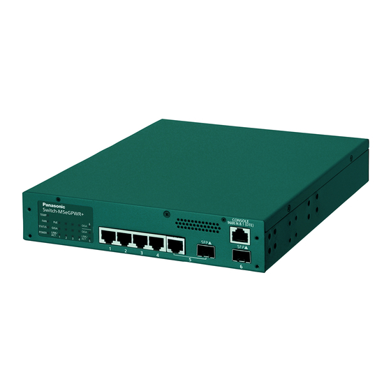
Page 10: Part Names And Functions
Part Names and Functions 10/100/1000BASE-T ports supporting PoE power supply 10/100/1000BASE-T port SFP extension slot Front panel Console port Power cord hook block Back panel Power port MAC Address label Ground terminal Serial number label Power port Connect the supplied power cord to this port and connect the other end into an electric outlet. - Page 11 PoE limit LED Fan sensor LED Temperature Power LED sensor LED Loop History mode LED Status/ECO mode LED POWER LED (Power) Green Light : Power is ON. : Power is OFF. STATUS/ECO LED (Status/ECO mode) Green Light : Operating in status mode. Green Blink : Operating in ECO mode.
- Page 12 Part Names and Functions Port LED (Left) Port LED (Right) • Port LED (Left) Green Light (when the LOOP HISTORY LED is off) : Link is established at 10/100/1000 Mbps. Green Light (when the LOOP HISTORY LED is Blink) : Within three days after a loop has been eliminated Green Blink : Data is being sent/received at 10/100/1000 Mbps.
-
Page 13: Led Display Change
2.1 LED display change Two types of Base modes The mode at the start is called “Base mode.” There are two types of Base modes: Status mode (factory default setting) and ECO mode. In the Status mode, you can check the terminal connection status by checking Port LED (left) lamps. In the ECO mode, all Port LED lamps are off. -
Page 14: Poe Power Supply Function
Part Names and Functions 2.2 PoE power supply function PoE power supply function operation overview Ports 1 to 4 support IEEE802.3at PoE. This function allows for power supply of up to 30 W through each port and 62W in total through the Switching Hub. PoE LIM. -
Page 15: Installation And Configuration
Installation and Configuration 3.1 Mounting to rack Use the supplied two 19-inch rack mount brackets and supplied eight screws (for fixing the mount brackets to the Switching Hub) to fix the mount brackets to the four holes on each side of the Switching Hub. Then securely install the Switching Hub on the rack using the supplied four screws (for a 19-inch rack mount) or screws supplied with the rack. -
Page 16: Configuration Of Ip Address (Basic)
Installation and Configuration 3.2 Configuration of IP address (Basic) (1) Connect this Switching Hub and PC with a RJ45–DSub 9-pin console cable and start up the terminal emulator (ZEQUO assist Plus, etc.). (2) Pressing Enter key 3 times opens Login screen. Enter Login name and Password (the default is "manager"... - Page 17 3.2 Configuration of IP address (Basic) Screen 2 Screen 1 Screen 3 Screen 4 Screen 5 * For the following, please see the PDF version Operating Instructions in CD-ROM. - Detailed configuration and management methods using the CLI. - Configuration and management method from ZEQUO assist Plus.
-
Page 18: Troubleshooting
Troubleshooting If you find any problem, please take the following steps to check. LED The POWER LED (Power) is not lit. Check if the power cord is disconnected. Please confirm that the power cord is securely connected to the power port. ... - Page 19 PoE power supply is impossible. Power is not supplied to a Powered Device. If you use an STP cable, PoE power supply may not be possible depending on the installation environment. In such cases, use a UTP cable. ...
Need help?
Do you have a question about the Switch-M5eGLPWR+ Series and is the answer not in the manual?
Questions and answers