Sign In
Upload
Manuals
Brands
Eaton Manuals
Monitor
POW-R-COMMAND 1000
Eaton POW-R-COMMAND 1000 Manuals
Manuals and User Guides for Eaton POW-R-COMMAND 1000. We have
10
Eaton POW-R-COMMAND 1000 manuals available for free PDF download: Installation And User Manual, User Manual, Instructions For The Use, Operation And Maintenance, Quick Start Manual
Eaton POW-R-COMMAND 1000 Installation And User Manual (200 pages)
Pulsar series
Brand:
Eaton
| Category:
UPS
| Size: 10.23 MB
Table of Contents
English
7
Environmental Protection
5
Table of Contents
7
1 Presentation
8
Standard Positions
8
Tower Position
8
Rack Position
8
Rear Panels
9
EX EXB (Optional Battery Module)
9
EX EXB RT (Optional Battery Module)
10
Control Panel
10
2 Installation
11
Unpacking and Contents Check
11
Installation of the RT Model in Tower Position
12
Installation of the RT Model in a Rack
12
Communication Ports
13
Connection of RS232 or USB Communication Port (Optional)
13
Installation of the Communication Cards (Optional)
14
Characteristics of the Contact Communication Port
14
Connection with a Flexpdu (Power Distribution Unit) Module
15
Connection with a Hotswap MBP Module
15
Hotswap MBP-Module Operation
16
UPS Connection Without a Flexpdu or Hotswap MBP Module
16
3 Operation
17
Start-Up and Normal Operation
17
Operation on Battery Power
17
Return of AC Power
18
UPS Shutdown
18
Using the UPS Remote Control Functions
18
4 Access to Measurements and Personalisation Data
20
Display Menus Arrangement
20
Access to Measurements
20
Personalisation Using the Control Panel
20
Personalisation Using External Software
21
5 Maintenance
22
Troubleshooting
22
Troubleshooting a UPS Equipped with the Hotswap MBP Module
23
Battery-Module Replacement
23
Safety Recommendations
23
Battery-Module Removal
23
Mounting the New Battery Module
25
Maintenance on a UPS Equipped with the Hotswap MBP Module
26
Training Centre
27
6 Appendices
28
Technical Specifications
28
Glossary
29
Français
35
1 Présentation
36
Positions Standards
36
Position Tour
36
Position Rack
36
Faces Arrières
37
EX EXB (Module Batterie Optionnel)
37
EX EXB RT (Module Batterie Optionnel)
38
Panneau D'affichage Et de Commande
38
2 Installation
39
Déballage Et Vérification du Contenu
39
Installation du Modèle RT en Position Tour
40
Installation du Modèle RT Dans un Rack
40
Ports de Communication
41
Raccordement du Port de Communication RS232 Ou USB (Facultatif)
41
Installation des Cartes de Communication (Option)
42
Caractéristiques du Port de Communication Par Contacts
42
Raccordements Avec un Module Flexpdu (Power Distribution Unit)
43
Raccordements Avec un Module Hotswap MBP
43
Fonctionnement du Module Hotswap MBP
44
Raccordements D'une ASI Dépourvue de Module Flexpdu Ou Hotswap MBP
44
3 Utilisation
45
Mise en Service Et Fonctionnement Normal
45
Fonctionnement Sur Batterie
45
Retour du Réseau Électrique
46
Arrêt de L'asi
46
Utilisation des Fonctions de Commande À Distance de L'asi
46
4 Accès Aux Mesures Et Personnalisation
48
Synoptique de L'afficheur
48
Accès Aux Mesures
48
Personnalisation Par Le Panneau de Commande
48
Personnalisation Par Logiciel Externe
49
5 Maintenance
50
Remplacement du Module Batterie
51
Rappel Sur Les Consignes de Sécurité
51
Démontage du Module Batterie
51
Remontage du Nouveau Module Batterie
53
Maintenance D'une ASI Équipée D'un Module Hotswap MBP
54
Centre de Formation
55
6 Annexes
56
Spécifications Techniques
56
Glossaire
57
Deutsch
63
1 Ansichten und Beschreibung
64
Aufstellvarianten
64
Tower-Modell
64
Rack-Modell
64
Rückansicht
65
EX EXB (Batterie-Erweiterungsmodul)
65
EX EXB RT (Batterie-Erweiterungsmodul)
66
Bedien- und Anzeigefeld
66
2 Aufstellung und Installation
67
Entfernen der Verpackung und Überprüfung des Lieferumfangs
67
Installation des Modells RT in Tower-Aufstellung
68
Installation des Modells RT in einem Rack
68
Kommunikationsschnittstellen
69
Anschluss der RS232- Bzw. der USB-Schnittstelle (Wahlweise)
69
Einbau der Optionalen Kommunikationskarten
70
Anschlussbelegung der Optionalen Kommunikationskarte
70
USV-Anschluss mit Optionalem Flexpdu-Installationsverteiler (Power Distribution Unit)
71
USV-Anschluss mit Optionalem Hotswap MBP-Modul
71
Funktionsweise des Hotswap MBP-Moduls
72
USV-Anschluss ohne Flexpdu- oder Hotswap MBP-Modul
72
3 Betriebszustände
73
Inbetriebnahme und Normalbetrieb
73
Batteriebetrieb
73
Rückkehr der Netzspannung
74
Abschaltung der USV
74
Verwendung der Fernbetätigungsfunktionen der USV
74
4 Kundenspezifische Anpassung und Abfrage der Messwerte
76
Darstellungsmöglichkeiten des Displays
76
Abfrage der Messwerte
76
Kundenspezifische Anpassung über Bedienfeld
76
Kundenspezifische Anpassung über Externe Software
77
5 Wartung und Service
78
Betriebsstörungen
78
Betriebsstörungen bei einer USV mit Hotswap MBP-Modul
79
Austausch des Batteriemoduls
79
Ausbau des Batteriemoduls
79
Einbau des Neuen Batteriemoduls
81
Trainingscenter
83
6 Anhang
84
Technische Daten
84
Fachbegriffe
85
Italiano
91
1 Presentazione
92
Posizioni Standard
92
Posizione Tower
92
Posizione Slot
92
Vista Posteriore
93
EX EXB (Modulo Batteria Opzionale)
93
EX EXB RT (Modulo Batteria Opzionale)
94
Pannello DI Visualizzazione E DI Comando
94
2 Installazione
95
Apertura Dell'imballaggio E Verifica del Contenuto
95
Installazione del Modello RT Nella Posizione Tower
96
Installazione del Modello RT in uno Slot
96
Porte DI Comunicazione
97
Raccordo Della Porta DI Comunicazione RS232 O USB (Facoltativa)
97
Installazione Delle Schede DI Comunicazione (Opzione)
98
Caratteristiche Della Porta DI Comunicazione Tramite Contatti
98
Raccordi con un Modulo Flexpdu (Power Distribution Unit)
99
Raccordi con un Modulo Hotswap MBP
99
Funzionamento del Modulo Hotswap MBP
100
Raccordo DI un ASI Privo DI Modulo Flexpdu O Hotswap MBP
100
3 Utilizzo
101
Messa in Servizio E Funzionamento Normale
101
Funzionamento Su Batteria
101
Ritorno Della Rete Elettrica
102
Arresto Dell'asi
102
Utilizzo Delle Funzioni DI Controllo Remoto Dell'asi
102
Sinottico del Display
104
Accesso alle Misure
104
Personalizzazione Tramite Il Pannello DI Comando
104
Personalizzazione Tramite Software Esterno
105
5 Manutenzione
106
Anomalie
106
Anomalie Su un ASI Dotato DI Modulo Hotswap MBP
107
Sostituzione del Modulo Batteria
107
Richiamo Sulle Istruzioni DI Sicurezza
107
Smontaggio del Modulo Batteria
107
Rimontaggio del Nuovo Modulo Batteria
109
Manutenzione DI un ASI Dotato DI Modulo Hotswap MBP
110
Centro DI Formazione
111
6 Allegati
112
Specifiche Tecniche
112
Glossario
113
Español
119
1 Presentación
120
Posiciones Estándar
120
Caras Traseras
121
EX EXB (Módulo Batería Opcional)
121
EX EXB RT (Módulo Batería Opcional)
122
Panel de Visualización y de Mando
122
2 Instalación
123
Desembalaje y Comprobación del Contenido
123
Instalación del Modelo RT en Posición de Torre
124
Instalación del Modelo RT en un Rack
124
Puertos de Comunicación
125
Conexión del Puerto de Comunicación RS232 O USB (Facultativo)
125
Instalación de las Tarjetas de Comunicación (Opcional)
126
Características del Puerto de Comunicación por Contactos
126
Conexiones a un Módulo Hotswap MBP
127
Funcionamiento del Módulo Hotswap
128
Conexiones de un SAI sin Módulo Flexpdu O Hotswap MBP
128
3 Utilización
129
Puesta en Servicio y en Funcionamiento Normal
129
Funcionamiento con Batería
129
Vuelta de la Corriente Eléctrica
130
Parada del SAI
130
Utilización de las Funciones de Mando a Distancia del SAI
130
Descripción Sinóptica del Visualizador
132
Acceso a las Medidas
132
Personalización Mediante el Software Externo
133
5 Mantenimiento
134
Anomalías
134
Anomalías en un SAI Equipado con un Módulo Hotswap MBP
135
Sustitución del Módulo de la Batería
135
Recordatorio de las Instrucciones de Seguridad
135
Desmontaje del Módulo de Batería
135
Montaje del Nuevo Módulo de Batería
137
Mantenimiento de un SAI Equipado con un Módulo Hotswap MBP
138
Centro de Formación
139
6 Anexos
140
Especificaciones Técnicas
140
Glosario
141
Dutch
147
1 Beschrijving
148
Standaardopstellingen
148
Rack-Opstelling
148
Achterkant
149
EX EXB (Optionele Accumodule)
149
EX EXB RT (Optionele Accumodule)
150
Bedieningspaneel
150
2 Installatie
151
Uitpakken en Controle Van de Inhoud
151
Installatie Van RT-Model in Tower-Opstelling
152
Installatie Van RT-Model in Rack-Opstelling
152
Communicatiepoorten
153
Aansluiten Van de RS232- of USB-Communicatiepoort (Facultatief)
153
Installatie Van Communicatiekaarten (Optie)
154
Eigenschappen Van de Contactgestuurde Communicatiepoort
154
Aansluiting Op Een Flexpdu-Module (Power Distribution Unit - Elektrische Verdeeldoos)
155
Aansluiting Op Een Hotswap MBP-Module
155
Werking Van de Hotswap MBP-Module
156
Aansluiten Van Een UPS Zonder Flexpdu-Of Hotswap MBP-Module
156
3 Gebruik
157
Ingebruikname en Normaal Bedrijf
157
Accubedrijf
157
Uitschakelen Van de UPS
158
Gebruik Van de Remote Bedieningsfuncties Van de UPS
158
Toegang Tot Metingen
160
Instellingen Via Bedieningspaneel
160
Instellingen Met Externe Software
161
5 Onderhoud
162
Storingen
162
Storingen Bij Een UPS Met Hotswap MBP-Module
163
Vervangen Van de Accumodule
163
Demonteren Van de Accumodule
163
Plaatsen Van de Nieuwe Accumodule
165
Onderhoud Van Een UPS Met Een Hotswap MBP-Module
166
Trainingscentrum
167
6 Bijlagen
168
Technische Gegevens
168
Definities
169
Advertisement
Eaton POW-R-COMMAND 1000 User Manual (97 pages)
Powerware Series
Brand:
Eaton
| Category:
Gateway
| Size: 1.43 MB
Table of Contents
Table of Contents
3
1 Introduction
6
Eaton Power Xpert Architecture
6
2 Getting Started
8
Installation Checklist
8
Installing the Card
10
Connecting the Card
12
IP Address Assignments
15
Verifying IP Addresses (DHCP Enabled)
16
Assigning IP Addresses (DHCP Disabled)
18
Network Configuration
23
Important Security Information
24
3 Configuring the Card
26
Navigating the Card's Web Page
27
Changing the Passwords
29
Setting the Date and Time
30
Configuring SNMP Options
31
Community Strings and Trap Recipients
31
Restricting SNMP Access
32
System Location and System Contact
33
Management from an SNMP NMS
33
Configuring Modbus TCP/IP Options
34
Configuring HTTP and HTTPS
35
Configuring the Energy Management System (EMS)
35
Configuring E-Mail Notification
37
Configuring EMP Settings
39
Configuring Auto Discovery Settings
40
Saving and Restoring Configuration Settings
40
Creating a Backup
40
Restoring a Backup
41
4 Root Certificate Authority Installation
42
Installing Root CA with Microsoft Internet Explorer 6
43
Installing Root CA with Microsoft Internet Explorer 7
51
Installing Root CA with Mozilla Firefox
53
5 MIB Files
56
Eaton PDU MIB
57
Mainpdu
57
Pdupanel
57
Pdubreaker
58
Eaton EMP MIB
58
Eaton Alarms+Traps MIB
58
Eaton OID Assignments
58
Entity MIB Files
59
6 Modbus Registers
60
Identifying the Breakers
61
PDU/RPP Breakers
61
RPM Breakers
62
Pole Data
63
Obtaining the Modbus Register Map
63
Returning Error Codes
64
Modbus Register Addressing
65
Modbus Function Codes
65
Data Formats
66
Data Addressing
67
PDU/RPP/RPM Unit ID Numbers
67
PDU/RPP/RPM Registers and Alarms
70
PDU/RPP/RPM Registers (FC 04)
70
PDU/RPP/RPM Alarms (FC 02)
72
Panel Registers and Alarms
73
Panel Summary Registers (FC 04)
73
Panel Alarms (FC 02)
75
Breaker Data and Alarms
76
Breaker #1 Data Registers (FC 04)
76
Calculating Breaker Register Numbers
77
Breaker Alarms (FC 02)
78
Emp (Fc 04)
79
Time or Date (FC 04)
80
7 Specifications
82
8 Operation and Maintenance
84
PXGX Series 1000 Card Panel Details
84
Indicator Descriptions
85
DIP Switch Description
87
Active Alarms
88
Generating Log Files
89
Upgrading the Card's Firmware
90
Two-Year Limited Warranty (US and Canada)
93
9 Service and Support
94
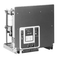
Eaton POW-R-COMMAND 1000 Instructions For The Use, Operation And Maintenance (63 pages)
Red Line Vacuum Circuit Breaker Elements
Brand:
Eaton
| Category:
Circuit breakers
| Size: 1.52 MB
Table of Contents
Table of Contents
4
Introduction
7
Type VCP-WR (Red Line Series) Ratings
7
Type VCP-WR Outlines and Dimensions
8
Safe Practices
15
Receiving, Handling and Storage
16
Receiving
16
Handling
16
Storage
16
Type VCP-WR Breaker Weights
17
Typical VCP-WR Escutcheon
24
Inspection and Operation
25
Initial Inspection
25
Manual Operation Check
25
Interface Verification
25
Description and Operation
26
Circuit Breaker Elements
26
Interrupter Assembly
26
5-2.1 Vacuum Interrupter
26
Typical VCP-WR Front Mounted Mechanism
27
5-2.2 Contact Erosion Indicator
28
Type VCP-WR Series 20 Interrupter Assemblies
28
Type VCP-WR Series 18 Interrupter Assemblies
28
Type VCP-WR Series 29 Interrupter Assemblies
28
5-2.3 "T" Cutout Loading Spring Indicator
29
5-2.4 Contact Wipe and Stroke
29
Stored Energy Mechanism
29
5-3.1 Operation of Stored Energy Mechanism
29
Typical Cutler-Hammer Vacuum Interrupter Shown Attached to Non-Sliding Current Transfer System
29
5-3.2 Charging
30
5-3.3 Closing Operation
30
5-3.4 Tripping Operation
30
5-3.5 Trip Free Operation
30
Control Schemes
30
Closing Cam and Trip Linkage
31
Charging Schematic
32
5-4.1 Timing
33
5-4.2 Terminal Blocks
33
Operations Counter
33
Breaker Element Interfacing
34
Introduction
34
General Guidelines
34
6-2.1 Electrical Clearances
34
6-2.2 Interphase Barriers
34
6-2.3 Front Cover (Faceplate)
34
6-2.4 Compartment Interface Verification
35
Series 18 Breaker Element Interfaces
35
6-3.1 Initial Interfacing Steps
35
6-3.2 Electrical Interfaces
35
6-3.3 Mechanical Interfaces
35
Typical VCP-WR Front Cover, Nameplate and Operational Indicators
35
Typical VCP-WR "DC" and "AC" Control Schematics
36
Series 20 Breaker Element Interfaces
37
6-4.1 Initial Interfacing Steps
37
Series 18 Primary Connection
37
Series 18 Showing Bottom Accessed Interlocks and MOC Operator
37
6-4.2 Electrical Interfaces
38
6-4.3 Mechanical Interfaces
38
Series 20 Primary Connection
38
Series 29 Breaker Element Interfaces
39
6-5.1 Initial Interfacing Steps
39
6-5.2 Electrical Interfaces
39
6-5.3 Mechanical Interfaces
39
Series 20 Showing Bottom Accessed Interlocks and MOC Operator
39
Series 29 Primary Connection
40
Series 29 Showing Bottom Accessed Interlocks and MOC Operator
40
Inspection and Maintenance
41
Introduction
41
Frequency of Inspection
41
Lubrication Points
41
Inspection and Maintenance Procedures
42
Vacuum Interrupter Integrity Test
43
Contact Erosion and Wipe
43
Insulation
44
Insulation Integrity Check
44
Vacuum Interrupter Showing Contact Erosion Indicator with Breaker Open
44
Vacuum Interrupter Showing Contact Erosion Indicator with Breaker Closed
44
Primary Circuit Resistance Check
45
Mechanism Check
45
Lubrication
45
Typical "T" Contact Wipe Indicator
45
Wipe Indication Procedure
46
Troubleshooting Chart
47
Renewal Parts
50
General
50
Ordering Instructions
50
Advertisement
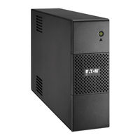
Eaton POW-R-COMMAND 1000 User Manual (84 pages)
Gateway Series
Brand:
Eaton
| Category:
Network Card
| Size: 4.71 MB
Table of Contents
Table of Contents
3
1 Getting Started
5
Installation Checklist
5
S 164201670 Rev
5
Installing the Card
7
Connecting the Card
9
IP Address Assignments
12
Verifying IP Addresses (DHCP Enabled)
13
Assigning IP Addresses (DHCP Disabled)
15
Network Configuration
20
2 Configuring the Card
23
Changing the Passwords
24
Setting the Date and Time
25
Configuring SNMP Options
26
Community Strings and Trap Recipients
26
Restricting SNMP Access
27
System Location and System Contact
27
Management from an SNMP NMS
28
Configuring Modbus TCP/IP Options
29
Configuring E-Mail Notification
30
Configuring EMP Settings
32
Configuring Auto Discovery Settings
33
3 Root Certificate Authority Installation
35
Installing Root CA with Microsoft Internet Explorer 6
36
Installing Root CA with Microsoft Internet Explorer 7
44
Installing Root CA with Mozilla Firefox
46
4 MIB Files
49
Eaton PDU MIB
50
Mainpdu
50
Pdupanel
50
Pdubreaker
50
Eaton EMP MIB
51
Eaton Alarms+Traps MIB
51
Eaton OID Assignments
51
Entity MIB Files
51
EATON Power Xpert
51
Gateway Series 1000 Card User's Guide
51
5 Modbus Registers
53
Modbus Register Addressing
54
Modbus Function Codes
54
Data Formats
54
Data Addressing
55
PDU/RPP Unit ID Numbers
56
PDU/RPP Registers and Alarms
58
PDU/RPP Registers (FC 04)
58
PDU/RPP Alarms (FC 02)
61
Panel Registers and Alarms
64
Panel Summary Registers (FC 04)
64
Panel Alarms (FC 01 or 02)
67
Breaker Data and Alarms
68
Breaker #1 Data Registers (FC 04)
68
Calculating Breaker Register Numbers
70
Breaker Alarms (FC 01 or 02)
71
Environmental Monitoring Probe (FC 03 or 04)
72
6 Specifications
73
7 Operation and Maintenance
75
Front-Panel Indicator Descriptions
75
DIP Switch Description
77
Generating Log Files
78
Upgrading the Card's Firmware
78
8 Service and Support
79
Two-Year Limited Warranty (US and Canada)
80
Eaton POW-R-COMMAND 1000 Instructions For The Use, Operation And Maintenance (71 pages)
Fixed Vacuum Circuit Breaker Elements
Brand:
Eaton
| Category:
Circuit breakers
| Size: 4.55 MB
Table of Contents
Table of Contents
4
Section 1 Introduction
7
Type VCP-WR (Red Line Series) Ratings
7
Type VCP-WR Outlines and Dimensions
9
Section 2 Safe Practices
21
Section 3 Receiving, Handling and Storage
22
Receiving
22
Handling
22
Storage
22
Type VCP-WR Breaker Weights
23
Front View VCP-WR Series 18
24
Rear View VCP-WR Series 18
25
Front View VCP-WR Series 20
26
Front View VCP-WR Series 29
28
Rear View VCP-WR Series 29
29
Typical VCP-WR Escutcheon
30
Section 4 Inspection and Operation
31
Initial Inaspection
31
Manual Operation Check
31
Interface Verification
31
Section 5 Description and Operation
32
Circuit Breaker Element
32
Interrupter Assembly
32
5-2.1 Vacuum Interrupter
32
Typical VCP-WR Front Mounted Mechanism
33
5-2.2 Contact Erosion Indicator
34
5-2.3 "T" Cutout Loading Spring Indicator
35
5-2.4 Contact Wipe and Stroke
35
Stored Energy Mechanism
35
5-3.1 Operation of Stored Energy Mechanism
35
5-3.2 Charging
36
5-3.3 Closing Operation
36
5-3.4 Tripping Operation
36
5-3.5 Trip Free Operation
36
Control Scheme
36
Closing Cam and Trip Linkage
37
Charging Schematic
38
5-4.1 Timing
39
5-4.2 Secondary Disconnects
39
Operations Counter
39
Section 6 Breaker Element Interfacing
40
Introduction
40
General Guidelines
40
6-2.1 Electrical Clearances
40
6-2.2 Interphase Barriers
40
6-2.3 Front Cover (Faceplate)
40
6-2.4 Compartment Interface Verification
41
Series 18 Breaker Element Interfaces
41
6-3.1 Initial Interfacing Steps
41
6-3.2 Electrical Interfaces
41
6-3.3 Mechanical Interfaces
41
Series 20 Breaker Element Interfaces
43
6-4.1 Initial Interfacing Steps
43
6-4.2 Electrical Interfaces
44
6-4.3 Mechanical Interfaces
44
Series 29 Breaker Element Interfaces
45
6-5.1 Initial Interfacing Steps
45
6-5.2 Electrical Interfaces
45
6-5.3 Mechanical Interfaces
45
Series 29 Primary Connection
46
Section 7 Inspection and Maintenance
47
Introduction
47
Frequency of Inspection
47
Inspection and Maintenance Procedures
48
Vacuum Interrupter Integrity Test
49
Contact Erosion and Wipe
50
Insulation
51
Insulation Integrity Check
51
Primary Circuit Resistance Check
51
Mechanism Check
51
Lubrication
51
Wipe Indication Procedure
52
Troubleshooting Chart
53
Section 8 Renewal Parts
56
General
56
Ordering Instructions
56
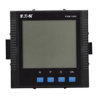
Eaton POW-R-COMMAND 1000 User Manual (30 pages)
Brand:
Eaton
| Category:
Measuring Instruments
| Size: 1.23 MB
Table of Contents
Table of Contents
2
1 Welcome to PXM1000
3
2 Getting Started
4
New Connection
4
Connection Settings
4
Add New Device
5
Connection
6
Getting Help
6
3 User Interface
7
Main Window
7
Main Menu
7
Toolbar
9
4 Functions
10
Basic Monitoring
10
Device Management
10
Data Logging
11
Import/Export Device Profile
17
PXM1000 Series
18
Readings
18
Settings
23
5 Troubleshooting
29
6 Installation
30
Installing
30
Uninstalling
30
System Requirements
30
Eaton POW-R-COMMAND 1000 Installation And User Manual (25 pages)
Brand:
Eaton
| Category:
UPS
| Size: 7.49 MB
Table of Contents
Operating Conditions
6
Operation
6
Conditions D'utilisation
7
Condizioni DI Utilizzo
9
Περιορισμοί Χρήσης
13
Eaton POW-R-COMMAND 1000 Installation And User Manual (8 pages)
Pulsar series
Brand:
Eaton
| Category:
UPS
| Size: 1.17 MB
Table of Contents
Quick Start
3
Battery Change
4
Technical Characteristics
5
Operating Conditions
6
Operation
6
Ups Connections
6
Troubleshooting
7
Eaton POW-R-COMMAND 1000 Quick Start Manual (8 pages)
programming display
Brand:
Eaton
| Category:
Monitor
| Size: 0.44 MB
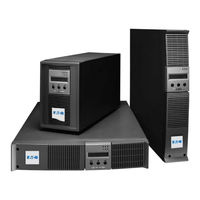
Eaton POW-R-COMMAND 1000 Installation And User Manual (7 pages)
Pulsar Series
Brand:
Eaton
| Category:
Power Supply
| Size: 0.75 MB
Advertisement
Related Products
Eaton 199740
Eaton DX 10000LXL
Eaton 1000H(XL)
Eaton 10000H(XL)
Eaton 1000 RT
Eaton 10000HXL31
Eaton 1000L
Eaton 1000LXL
Eaton 1000VA
Eaton 5SC 1000i Rack2U
Eaton Categories
UPS
Circuit breakers
Industrial Equipment
Switch
Industrial Electrical
More Eaton Manuals
Login
Sign In
OR
Sign in with Facebook
Sign in with Google
Upload manual
Upload from disk
Upload from URL