Sign In
Upload
Manuals
Brands
Agilent Technologies Manuals
Measuring Instruments
8564EC
Agilent Technologies 8564EC Manuals
Manuals and User Guides for Agilent Technologies 8564EC. We have
2
Agilent Technologies 8564EC manuals available for free PDF download: User Manual, Service Manual
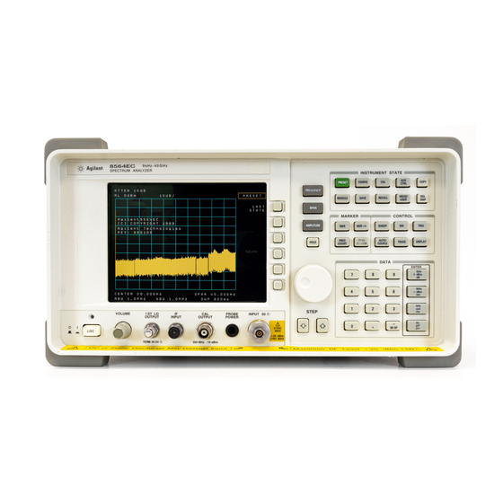
Agilent Technologies 8564EC User Manual (716 pages)
Agilent Technologies 8560 E-Series and EC-Series Spectrum Analyzers
Brand:
Agilent Technologies
| Category:
Measuring Instruments
| Size: 11.47 MB
Table of Contents
Table of Contents
5
1 Quick Start Guide
21
What You'll Find in this Chapter
22
Initial Inspection
25
Figure 1-1 Accessories Supplied
27
Turning the Spectrum Analyzer on for the First Time
28
Figure 1-2 Selecting the Correct Line Voltage
28
Making a Basic Measurement
30
Figure 1-3 300 Mhz Calibration Signal Connection
30
Figure 1-4 Softkey Menu
31
Figure 1-5 300 Mhz Center Frequency
32
Figure 1-6 20 Mhz Frequency Span
33
Figure 1-7 Activated Normal Marker
33
Figure 1-8 −10 Dbm Reference Level
34
Reference Level Calibration
35
Figure 1-9 . Peaked Signal to Reference Level
35
Front Panel Overview
36
Figure 1-10 Front Panel of an 8560 E-Series or EC- Series Spectrum Analyzer
36
Figure 1-11 Display Annotation
39
Rear Panel Overview
41
Figure 1-12 Rear Panel Functions - 8560 E-Series
41
Figure 1-13 Rear Panel Functions - 8560 EC-Series
41
Assistance
44
General Safety Considerations
45
8560 E-Series and EC-Series Spectrum Analyzer Documentation Description
46
Manuals Available Separately
47
2 Making Measurements Making Measurements
50
Example 1: Resolving Closely Spaced Signals (with Resolution Bandwidth)
51
Figure 2-1 1 Khz Signal Separation
52
Figure 2-2 2 Khz Signal Separation
52
Figure 2-3 Bandwidth Shape Factor
54
Figure 2-4 100 Khz Bandwidth Resolution
55
Figure 2-5 300 Khz Bandwidth Resolution
55
Example 2: Improving Amplitude Measurements with Ampcor
56
Figure 2-6 Ampcor Measurement Setup
57
Example 3: Modulation
60
Figure 2-7 an Amplitude-Modulated Signal
61
Figure 2-8 Percentage of Modulation
61
Figure 2-9 FM Deviation Test Setup
62
Figure 2-10 Bessel Functions for Determining Modulation Index
63
Figure 2-11 Markers Show Modulating Frequency
64
Figure 2-12 a Frequency-Modulated Signal
65
Figure 2-13 FM Signal with Carrier at a Null
66
Figure 2-14 FM Signal with First Sidebands at a Null
66
Example 4: Harmonic Distortion
67
Figure 2-15 Input Signal and Harmonics
68
Figure 2-16 Peak of Signal Is Positioned at Reference Level for Maximum Accuracy
69
Figure 2-17 Harmonic Distortion in Dbc (Marker Threshold Set to −70 Db)
70
Figure 2-18 Percentage of Distortion Versus Harmonic Amplitude
71
Figure 2-19 Input Signal Displayed in a 1 Mhz Span
73
Figure 2-20 Second Harmonic Displayed in Dbc
74
Example 5: Third-Order Intermodulation Distortion
75
Figure 2-21 Third-Order Intermodulation Test Setup
76
Figure 2-22 Signals Centered on Spectrum Analyzer Display
77
Figure 2-23 Signal Peak Set to Reference Level
78
Figure 2-24 Intermodulation Distortion Measured in Dbc
79
Figure 2-25 Display with Title
80
Example 6: am and FM Demodulation
81
Figure 2-26 am and FM Demodulation Test Setup
82
Figure 2-27 FM Band
82
Figure 2-28 . Place a Marker on the Signal of Interest, then Demodulate
83
Example 7: Stimulus-Response Measurements
84
Figure 2-29 Block Diagram of a Spectrum Analyzer and Tracking Generator System
84
Figure 2-30 Transmission Measurement Test Setup
85
Figure 2-31 Tracking-Generator Output Power Activated
86
Figure 2-32 Adjust Analyzer Settings According to the Measurement Requirement
87
Figure 2-33 Decrease the Resolution Bandwidth to Improve Sensitivity
88
Figure 2-34 Manual Tracking Adjustment Compensates for Tracking Error
89
Figure 2-35 Guided Calibration Routines Prompt the User
90
Figure 2-36 the Thru Trace Is Displayed in Trace B
90
Figure 2-37 Normalized Trace
91
Figure 2-38 . Measure the Rejection Range with Delta Markers
92
Figure 2-39 NORM REF LVL Adjusts the Trace Without Changing Analyzer Settings
93
Figure 2-40 . Increase the Dynamic Measurement Range by Using RANGE LVL
94
Figure 2-41 . Normalized Frequency Response Trace of a Preamplifier
95
Figure 2-42 NORM REF LVL Is a Trace Function
96
Figure 2-43 RANGE LVL Adjusts Analyzer for Compression-Free Measurements
96
Example 8: External Millimeter Mixers (Unpreselected)
98
Figure 2-44 External Mixer Setup (A) Without Bias; (B) with Bias
99
Figure 2-45 Select the Band of Interest
101
Figure 2-46 Store and Correct for Conversion Loss
102
Figure 2-47 . Signal Responses Produced by a 50 Ghz Signal in U Band
103
Figure 2-48 Response for Invalid Signals
104
Figure 2-49 Response for Valid Signals
104
Figure 2-50 SIG ID at MKR Performed on an Image Signal
105
Figure 2-51 SIG ID at MKR Performed on a True Signal
106
Example 9: Adjacent Channel Power Measurement
108
Figure 2-52 Adjacent Channel Power Measurement Test Setup
109
Figure 2-53 Adjacent Channel Power Parameters
110
Figure 2-54 Adjacent Channel Power Measurement Results
111
Figure 2-55 ACP Graph Display
112
Figure 2-56 . Trigger Configuration for Gated Method, Non-Option 001
123
Figure 2-57 . Trigger Configuration for Gated Method, Option 001
124
Example 10: Power Measurement Functions
125
Example 11: Time-Gated Measurement
129
Figure 2-58 . Simplified Digital Mobile-Radio Signal in Time Domain
129
Figure 2-59 Frequency of the Combined Signals of the Radios
130
Figure 2-60 . Time-Gated Spectrum of Signal Number 1
130
Figure 2-61 . Time-Gated Spectrum of Signal Number 2
131
Figure 2-62 Block Diagram of the Spectrum Analyzer with Time Gate
132
Figure 2-63 Timing Relationship of Signals During Gating
133
Figure 2-64 Spectrum Within Pulse #1
133
Figure 2-65 . Using Time-Gating to View Signal 1
134
Figure 2-66 Spectrum Within Pulse #2
134
Figure 2-67 . Using Time-Gating to View Signal 2
135
Figure 2-68 Connection Diagram for Time-Gated Spectrum Measurements
137
Figure 2-69 Connection Diagram for Example
137
Figure 2-70 Frequency Spectrum of Signal Without Gating
140
Figure 2-71 Oscilloscope Display
140
Figure 2-72 Spectrum Analyzer Display
141
Figure 2-73 Using Positive or Negative Triggering
142
Figure 2-74 Time-Domain Parameters
143
Figure 2-75 Positioning the Gate
145
Figure 2-76 Best Position for Gate
145
Figure 2-77 Setup Time for Interpulse Measurement
146
Figure 2-78 Resolution Bandwidth Filter Charge-Up Effects
147
Figure 2-79 . Gate Positioning Parameters
151
Example 12: Making Time-Domain Measurements with Sweep Delay
154
Figure 2-80 Pulsed-RF Signal in Time Domain
154
Figure 2-81 Display of Zero-Span Without Sweep Delay
156
Figure 2-82 Display of Zero-Span with Sweep Delay
156
Example 13: Making Pulsed RF Measurements
158
Figure 2-83 Main Lobe and Side Lobes
159
Figure 2-84 Trace Displayed as a Solid Line
160
Figure 2-85 Center Frequency at Center of Main Lobe
160
Figure 2-86 . Markers Show Sidelobe Ratio
161
Figure 2-87 Markers Show Pulse Width
162
Figure 2-88 . Measuring Pulse Repetition Frequency
163
3 Softkey Menus
165
Menu Trees
166
Figure 3-1 AMPLITUDE Key Menu Tree
166
Figure 3-2 AUTO COUPLE Menu Tree
167
Figure 3-3 AUX CTRL (1 of 3) Key Menu Tree
168
Figure 3-4 AUX CTRL (2 of 3) Key Menu Tree
169
Figure 3-5 AUX CTRL (3 of 3) Key Menu Tree
170
Figure 3-6 BW Key Menu
170
Figure 3-7 CAL Key Menu Tree
171
Figure 3-8 CONFIG Key Menu Tree
172
Figure 3-9 COPY Key
173
Figure 3-10 DISPLAY Key Menu Tree
173
Figure 3-11 FREQ COUNT Key Menu
174
Figure 3-12 FREQUENCY Key Menu Tree
174
Figure 3-13 HOLD Key
174
Figure 3-14 MEAS/USER Key Menu Tree
175
Figure 3-15 ACP MENU Key Menu Tree
176
Figure 3-16 MKR Key Menu
176
Figure 3-17 MKR-> Key Menu
177
Figure 3-18 MODULE Key Menus
177
Figure 3-19 PEAK SEARCH Key Menu Tree
178
Figure 3-20 PRESET Key
178
Figure 3-21 RECALL Key Menu Tree
179
Figure 3-22 SAVE Key Menu Tree
180
Figure 3-23 SGL SWP Key
180
Figure 3-24 SPAN Key Menu
180
Figure 3-25 SWEEP Key Menu Tree
181
Figure 3-26 TRACE Key Menu Tree
181
Figure 3-27 TRIG Key Menu
181
4 Key Function Descriptions
183
Key Function Tables
184
Key Descriptions
204
Figure 4-1 Channel Bandwidth Parameters
210
Figure 4-2 ACP Graph Display
213
Figure 4-3 CRT Alignment Pattern
228
Figure 4-4 Tracking Error
247
Figure 4-5 . PEAK EXCURSN Defines the Peaks on a Trace
258
5 Programming Programming Features
290
Setup Procedure for Remote Operation
291
Figure 5-1 8560E Connected to an HP 9000 Series 300 Computer
292
Communication with the System
293
Figure 5-2 Output Statement Example (I)
294
Figure 5-3 Output Statement Example (II)
294
Figure 5-4 Output Statement Example (III)
295
Initial Program Considerations
297
Program Timing
298
Figure 5-5 Invalid Trace Information
299
Figure 5-6 Updated Trace Information
300
Figure 5-7 Update Trace with TS before Executing Marker Commands
302
Data Transfer to Computer
303
Figure 5-8 Data Transferred in TDF M Format
309
Input and Output Buffers
316
Figure 5-9 Buffer Summary
318
Math Functions
319
Figure 5-10 Display Units
323
Creating Screen Titles
324
Figure 5-11 Screen Titles Appear in the Upper-Right Corner of the Graticule
324
Generating Plots and Prints Remotely
327
Figure 5-12 P1 and P2 Coordinates
328
Monitoring System Operation
332
6 Programming Command Cross Reference
339
Programming Command Cross Reference Features
340
Front Panel Key Versus Command
341
Programming Command Versus Front Panel Key
352
7 Language Reference
369
Language Reference Features
370
Syntax Diagram Conventions
371
Figure 7-1 Command Syntax Figure
371
Figure 7-2 Numeric Value Query Response
372
Figure 7-3 Binary State Query Response
372
Programming Commands
377
ACPACCL Accelerate Adjacent Channel Power Measurement
378
Figure 7-4 ACPACCL Syntax
378
Figure 7-5 ACPACCL Query Response
379
ACPALPHA Adjacent Channel Power Alpha Weighting
380
Figure 7-6 ACPALPHA Syntax
380
Figure 7-7 ACPALPHA Query Response
380
ACPALTCH Adjacent Channel Power Alternate Channels
381
Figure 7-8 ACPALTCH Syntax
381
Figure 7-9 ACPALTCH Query Response
381
ACPBRPER Adjacent Channel Power Burst Period
382
Figure 7-10 ACPBRPER Syntax
382
Figure 7-11 ACPBRPER Query Response
382
ACPBRWID Adjacent Channel Power Burst Width
383
Figure 7-12 ACPBRWID Syntax
383
Figure 7-13 ACPBRWID Query Response
383
ACPBW Adjacent Channel Power Channel Bandwidth
384
Figure 7-14 ACPBW Syntax
384
Figure 7-15 ACPBW Query Response
384
ACPCOMPUTE Adjacent Channel Power Compute
385
Figure 7-16 ACPCOMPUTE Syntax
385
ACPFRQWT Adjacent Channel Power Frequency Weighting
387
Figure 7-17 ACPFRQWT Syntax
387
Figure 7-18 ACPFRQWT Query Response
387
ACPGRAPH Adjacent Channel Power Graph
388
Figure 7-19 ACPGRAPH Syntax
388
Figure 7-20 ACPGRAPH Query Response
389
ACPLOWER Lower Adjacent Channel Power
390
Figure 7-21 ACPLOWER Syntax
390
Figure 7-22 ACPLOWER Query Response
390
ACPMAX Maximum Adjacent Channel Power
391
Figure 7-23 ACPMAX Syntax
391
Figure 7-24 ACPMAX Query Response
391
ACPMEAS Measure Adjacent Channel Power
392
Figure 7-25 ACPMEAS Syntax
392
ACPMETHOD Adjacent Channel Power Measurement Method
394
Figure 7-26 ACPMETHOD Syntax
394
Figure 7-27 ACPMETHOD Query Response
396
ACPMSTATE Adjacent Channel Power Measurement State
397
Figure 7-28 ACPMSTATE Syntax
397
Figure 7-29 ACPMSTATE Query Response
398
ACPPWRTX Total Power Transmitted
399
Figure 7-30 ACPPWRTX Syntax
399
Figure 7-31 ACPPWRTX Query Response
399
ACPRSLTS Adjacent Channel Power Measurement Results
400
Figure 7-32 ACPRSLTS Syntax
400
Figure 7-33 ACPRSLTS Query Response
402
ACPSP Adjacent Channel Power Channel Spacing
403
Figure 7-34 ACPSP Syntax
403
Figure 7-35 ACPSP Query Response
404
ACPT Adjacent Channel Power T Weighting
405
Figure 7-36 ACPT Syntax
405
Figure 7-37 ACPT Query Response
405
ACPUPPER Upper Adjacent Channel Power
406
Figure 7-38 ACPUPPER Syntax
406
Figure 7-39 ACPUPPER Query Response
406
ADJALL lo and if Adjustments
407
Figure 7-40 ADJALL Syntax
407
ADJCRT Adjust CRT Alignment
408
Figure 7-41 ADJCRT Syntax
408
Figure 7-42 CRT Alignment Pattern
409
ADJIF Adjust if
410
Figure 7-43 ADJIF Syntax
410
Figure 7-44 ADJIF Query Response
411
AMB Trace a Minus Trace B
412
Figure 7-45 AMB Syntax
412
Figure 7-46 AMB Query Response
413
AMBPL Trace a Minus Trace B Plus Display Line
414
Figure 7-47 AMBPL Syntax
414
Figure 7-48 AMBPL Query Response
415
AMPCOR Amplitude Correction
416
Figure 7-49 AMPCOR Syntax
416
Figure 7-50 AMPCOR Query Response
416
AMPCORDATA Amplitude Correction Data
417
Figure 7-51 AMPCORDATA Syntax
417
Figure 7-52 AMPCORDATA Query Response
418
AMPCORSIZE Amplitude Correction Data Array Size
419
Figure 7-53 AMPCORSIZE Syntax
419
Figure 7-54 AMPCORSIZE Query Response
419
AMPCORRCL Amplitude Correction Recall
420
Figure 7-55 AMPCORRCL Syntax
420
AMPCORSAVE Amplitude Correction Save
421
Figure 7-56 AMPCORSAVE Syntax
421
ANNOT Annotation On/Off
422
Figure 7-57 ANNOT Syntax
422
Figure 7-58 ANNOT Query Response
422
APB Trace a Plus Trace B
423
Figure 7-59 APB Syntax
423
AT Input Attenuation
424
Figure 7-60 at Syntax
424
Figure 7-61 at Query Response
425
AUNITS Absolute Amplitude Units
426
Figure 7-62 AUNITS Syntax
426
Figure 7-63 AUNITS Query Response
427
AUTOCPL Auto Coupled
428
Figure 7-64 AUTOCPL Syntax
428
AXB Trace a Exchange Trace B
429
Figure 7-65 AXB Syntax
429
BLANK Blank Trace
430
Figure 7-66 BLANK Syntax
430
BML Trace B Minus Display Line
431
Figure 7-67 BML Syntax
431
CARROFF Carrier off Power
432
Figure 7-68 CARROFF Syntax
432
Figure 7-69 CARROFF Query Response
432
CARRON Carrier on Power
433
Figure 7-70 CARRON Syntax
433
Figure 7-71 CARRON Query Response
433
CF Center Frequency
434
Figure 7-72 CF Syntax
434
Figure 7-73 CF Query Response
435
CHANPWR Channel Power
436
Figure 7-74 CHANPWR Syntax
436
Figure 7-75 CHANPWR Query Response
437
CHANNEL Channel Selection
438
Figure 7-76 CHANNEL Syntax
438
CHPWRBW Channel Power Bandwidth
439
Figure 7-77 CHPWRBW Syntax
439
Figure 7-78 CHPWRBW Query Response
439
CLRW Clear Write
440
Figure 7-79 CLRW Syntax
440
CNVLOSS Conversion Loss
441
Figure 7-80 CNVLOSS Syntax
441
Figure 7-81 CNVLOSS Query Response
442
CONTS Continuous Sweep
443
Figure 7-82 CONTS Syntax
443
COUPLE Input Coupling
444
Figure 7-83 COUPLE Syntax
444
Figure 7-84 COUPLE Query Response
444
DELMKBW Occupied Power Bandwidth Within Delta Marker
445
Figure 7-85 DELMKBW Syntax
445
Figure 7-86 DELMKBW Query Response
446
DEMOD Demodulation
447
Figure 7-87 DEMOD Syntax
447
Figure 7-88 DEMOD Query Response
447
DEMODAGC Demodulation Automatic Gain Control
449
Figure 7-89 DEMODAGC Syntax
449
Figure 7-90 DEMODAGC Query Response
449
DEMODT Demodulation Time
451
Figure 7-91 DEMODT Syntax
451
Figure 7-92 DEMODT Query Response
452
DET Detection Modes
453
Figure 7-93 DET Syntax
453
Figure 7-94 DET Query Response
454
DL Display Line
455
Figure 7-95 DL Syntax
455
Figure 7-96 DT Query Response
456
DLYSWP Delay Sweep
457
Figure 7-97 DLYSWP Syntax
457
Figure 7-98 DLYSWP Query Response
458
DONE Done
459
Figure 7-99 DONE Syntax
459
Figure 7-100 DONE Query Response
459
ERR Error
460
Figure 7-101 ERR Syntax
460
Figure 7-102 ERR Query Response
460
ET Elapsed Time
462
Figure 7-103 ET Syntax
462
Figure 7-104 ET Query Response
462
EXTMXR External Mixer Mode
463
Figure 7-105 EXTMXR Syntax
463
Figure 7-106 EXTMXR Query Response
463
FA Start Frequency
464
Figure 7-107 FA Syntax
464
Figure 7-108 FA Query Response
465
FB Stop Frequency
466
Figure 7-109 FB Syntax
466
Figure 7-110 FB Query Response
467
FDIAG Frequency Diagnostics
468
Figure 7-111 FDIAG Syntax
468
Figure 7-112 FDIAG Query Response
469
FDSP Frequency Display off
470
Figure 7-113 FDSP Syntax
470
Figure 7-114 FDSP Query Response
470
FFT Fast Fourier Transform
472
Figure 7-115 FFT Syntax
472
FOFFSET Frequency Offset
475
Figure 7-116 FOFFSET Syntax
475
Figure 7-117 FOFFSET Query Response
476
FREF Frequency Reference
477
Figure 7-118 FREF Syntax
477
Figure 7-119 FREF Query Response
477
FS Full Span
478
Figure 7-120 FS Syntax
478
FULBAND Full Band
479
Figure 7-121 FULBAND Syntax
479
GATE Gate
481
Figure 7-122 GATE Syntax
481
Figure 7-123 GATE Query Response
482
GATECTL Gate Control
483
Figure 7-124 GATECTL Syntax
483
Figure 7-125 GATECTL Query Response
483
GD Gate Delay
484
Figure 7-126 GD Syntax
484
Figure 7-127 GD Query Response
484
GL Gate Length
485
Figure 7-128 GL Syntax
485
Figure 7-129 GL Query Response
485
GP Gate Polarity
486
Figure 7-130 GP Syntax
486
Figure 7-131 GP Query Response
486
GRAT Graticule On/Off
487
Figure 7-132 GRAT Syntax
487
Figure 7-133 GRAT Query Response
487
HD Hold
488
Figure 7-134 HD Syntax
488
HNLOCK Harmonic Number Lock
489
Figure 7-135 HNLOCK Syntax
489
Figure 7-136 HNLOCK Query Response
490
HNUNLK Unlock Harmonic Number
491
Figure 7-137 HNUNLK Syntax
491
ID Output Identification
492
Figure 7-138 ID Syntax
492
Figure 7-139 ID Query Response
492
IDCF Signal Identification to Center Frequency
493
Figure 7-140 IDCF Syntax
493
IDFREQ Signal Identified Frequency
494
Figure 7-141 IDFREQ Syntax
494
Figure 7-142 IDFREQ Query Response
494
IP Instrument Preset
495
Figure 7-143 IP Syntax
495
LG Logarithmic Scale
498
Figure 7-144 LG Syntax
498
Figure 7-145 LG Query Response
498
LN Linear Scale
500
Figure 7-146 LN Syntax
500
MBIAS Mixer Bias
501
Figure 7-147 MBIAS Syntax
501
Figure 7-148 MBIAS Query Response
502
MEANPWR Mean Power Measurement
503
Figure 7-149 MEANPWR Syntax
503
Figure 7-150 MEANPWR Query Response
504
MEAS Measurement Status
505
Figure 7-151 MEAS Syntax
505
Figure 7-152 MEAS Query Response
505
MINH Minimum Hold
506
Figure 7-153 MINH Syntax
506
MKA Marker Amplitude
507
Figure 7-154 MKA Syntax
507
Figure 7-155 MKA Query Response
507
MKBW Marker Bandwidth
508
Figure 7-156 MKBW Syntax
508
MKCF Marker to Center Frequency
509
Figure 7-157 MKCF Syntax
509
MKCHEDGE Marker to Channel Edges
510
Figure 7-158 MKCHEDGE Syntax
510
MKD Marker Delta
511
Figure 7-159 MKD Syntax
511
Figure 7-160 MKD Query Response
512
MKDELCHBW Delta Markers to Channel Power Bandwidth
513
Figure 7-161 MKDELCHBW Syntax
513
MKDR Reciprocal of Marker Delta
514
Figure 7-162 MKDR Syntax
514
Figure 7-163 MKDR Query Response
515
MKF Marker Frequency
516
Figure 7-164 MKF Syntax
516
Figure 7-165 MKF Query Response
517
MKFC Frequency Counter
518
Figure 7-166 MKFC Syntax
518
MKFCR Frequency Counter Resolution
519
Figure 7-167 MKFCR Syntax
519
Figure 7-168 MKFCR Query Response
519
MKMCF Marker Mean to the Center Frequency
521
Figure 7-169 MKMCF Syntax
521
MKMIN Marker to Minimum
522
Figure 7-170 MKMIN Syntax
522
MKN Marker Normal
523
Figure 7-171 MKN Syntax
523
Figure 7-172 MKN Query Response
524
MKNOISE Marker Noise
525
Figure 7-173 MKNOISE Syntax
525
Figure 7-174 MKNOISE Query Response
525
MKOFF Marker off
527
Figure 7-175 MKOFF Syntax
527
MKPK Peak Search
528
Figure 7-176 MKPK Syntax
528
MKPT Marker Threshold
530
Figure 7-177 MKPT Syntax
530
Figure 7-178 MKPT Query Response
530
MKPX Peak Excursion
532
Figure 7-179 MKPX Syntax
532
Figure 7-180 MKPX Determines Which Signals Are Considered Peaks
533
Figure 7-181 MKPX Query Response
533
MKRL Marker to Reference Level
535
Figure 7-182 MKRL Syntax
535
MKSP Marker Delta to Span
536
Figure 7-183 MKSP Syntax
536
MKSS Marker to Center Frequency Step-Size
537
Figure 7-184 MKSS Syntax
537
MKT Marker Time
538
Figure 7-185 MKT Syntax
538
Figure 7-186 MKT Query Response
538
MKTRACK Signal Track
539
Figure 7-187 MKTRACK Syntax
539
Figure 7-188 MKTRACK Query Response
540
ML Mixer Level
541
Figure 7-189 ML Syntax
541
Figure 7-190 ML Query Response
541
MXMH Maximum Hold
543
Figure 7-191 MXMH Syntax
543
MXRMODE Mixer Mode
544
Figure 7-192 MXRMODE Syntax
544
Figure 7-193 MXRMODE Query Response
544
NORMLIZE Normalize Trace Data
545
Figure 7-194 NORMALIZE Syntax
545
Figure 7-195 NORMALIZE Query Response
546
NRL Normalized Reference Level
547
Figure 7-196 NRL Syntax
547
Figure 7-197 NRL Query Response
548
NRPOS Normalized Reference Position
550
Figure 7-198 NRPOS Syntax
550
Figure 7-199 NRPOS Query Response
551
OCCUP Percent Occupied Power Bandwidth
552
Figure 7-200 OCCUP Syntax
552
Figure 7-201 OCCUP Query Response
552
OP Output Display Parameters
553
Figure 7-202 OP Syntax
553
Figure 7-203 OP Query Response
553
PLOT Plot Display
554
Figure 7-204 PLOT Syntax
554
PLOTORG Display Origins
556
Figure 7-205 PLOTORG Syntax
556
Figure 7-206 PLOTORG Query Response
556
PLOTSRC Plot Source
558
Figure 7-207 PLOTSRC Syntax
558
Figure 7-208 PLOT SRC Query Response
559
PP Preselector Peak
560
Figure 7-209 PP Syntax
560
PRINT Print
561
Figure 7-210 PRINT Syntax
561
PSDAC Preselector DAC Number
563
Figure 7-211 PSDAC Syntax
563
Figure 7-212 PSDAC Query Response
563
PSTATE Protect State
565
Figure 7-213 PSTATE Syntax
565
Figure 7-214 PSTATE Query Response
565
PWRBW Power Bandwidth (Full Trace)
567
Figure 7-215 PWRBW Syntax
567
Figure 7-216 PWRBW Query Response
567
RB Resolution Bandwidth
569
Figure 7-217 RB Syntax
569
Figure 7-218 RB Query Response
570
RBR Resolution Bandwidth to Span Ratio
571
Figure 7-219 RBR Syntax
571
Figure 7-220 RBR Query Response
571
RCLOSCAL Recall Open/Short Average
573
Figure 7-221 RCLOSCAL Syntax
573
RCLS Recall State
575
Figure 7-222 RCLS Syntax
575
RCLT Recall Trace
576
Figure 7-223 RCLT Syntax
576
RCLTHRU Recall Thru
577
Figure 7-224 RCLTHRU Syntax
577
REV Revision Number
579
Figure 7-225 REV Syntax
579
Figure 7-226 REV Query Response
579
RL Reference/Range Level
580
Figure 7-227 RL Syntax
580
Figure 7-228 RL Query Response
582
RLCAL Reference Level Calibration
583
Figure 7-229 RLCAL Syntax
583
ROFFSET Amplitude Reference Offset
585
Figure 7-230 ROFFSET Syntax
585
Figure 7-231 ROFFSET Query Response
586
RQS Request Service Conditions
587
Figure 7-232 RQS Syntax
587
Figure 7-233 RQS Query Response
588
SAVES Save State
589
Figure 7-234 SAVES Syntax
589
SAVET Save Trace
590
Figure 7-235 SAVET Syntax
590
Figure 7-236 SER Syntax
591
Figure 7-237 SER Query Response
591
SER Serial Number
591
Figure 7-238 SIGID Syntax
592
SIGID Signal Identification
592
Figure 7-239 SIGID Query Response
593
Figure 7-240 SNGLS Syntax
594
SNGLS Single Sweep
594
Figure 7-241 SP Syntax
595
SP Frequency Span
595
Figure 7-242 SP Query Response
596
Figure 7-243 SQUELCH Syntax
597
SQUELCH Squelch
597
Figure 7-244 SQUELCH Query Response
598
Figure 7-245 SRCALC Syntax
599
Figure 7-246 SRCALC Query Response
599
SRCALC Source Leveling Control
599
Figure 7-247 SRCCRSTK Syntax
600
Figure 7-248 SRCCRSTK Query Response
600
SRCCRSTK Coarse Tracking Adjust
600
Figure 7-249 SRCFINTK Syntax
602
SRCFINTK Fine Tracking Adjust
602
Figure 7-250 SRCFINTK Query Response
603
Figure 7-251 SRCPOFS Syntax
604
SRCPOFS Source Power Offset
604
Figure 7-252 SRCPOFS Query Response
605
Figure 7-253 SRCPSTP Syntax
606
Figure 7-254 SRCPSTP Query Response
606
SRCPSTP Source Power Step
606
Figure 7-255 SRCPSWP Syntax
608
SRCPSWP Source Power Sweep
608
Figure 7-256 SRCPSWP Query Response
609
Figure 7-257 SRCPWR Syntax
610
SRCPWR Source Power
610
Figure 7-258 SRCPWR Query Response
611
Figure 7-259 SRCTKPK Syntax
612
SRCTKPK Source Tracking Peak
612
Figure 7-260 SRQ Syntax
613
SRQ Service Request
613
Figure 7-261 SS Syntax
614
SS Center Frequency Step-Size
614
Figure 7-262 SS Query Response
615
Figure 7-263 ST Syntax
616
ST Sweep Time
616
Figure 7-264 ST Query Response
617
Figure 7-265 STB Syntax
618
STB Status Byte Query
618
Figure 7-266 STB Query Response
619
Figure 7-267 STOREOPEN Syntax
620
STOREOPEN Store Open
620
Figure 7-268 STORESHORT Syntax
622
STORESHORT Store Short
622
Figure 7-269 STORETHRU Syntax
624
STORETHRU Store Thru
624
Figure 7-270 SWPCPL Syntax
626
Figure 7-271 SWPCPL Query Response
626
SWPCPL Sweep Couple
626
Figure 7-272 SWPOUT Syntax
628
SWPOUT Sweep Output
628
Figure 7-273 SWPOUT Query Response
629
Figure 7-274 TDF Syntax
630
TDF Trace Data Format
630
Figure 7-275 TDF Query Response
631
Figure 7-276 TH Syntax
632
TH Threshold
632
Figure 7-277 TH Query Response
633
Figure 7-278 TITLE Syntax
634
TITLE Title Entry
634
Figure 7-279 TM Syntax
636
TM Trigger Mode
636
Figure 7-280 TM Query Response
637
Figure 7-281 TRA/TRB Syntax
638
TRA/TRB Trace Data Input/Output
638
Figure 7-282 TRA/TRB Query Response
639
Figure 7-283 TRIGPOL Syntax
641
Figure 7-284 TRIGPOL Query Response
641
TRIGPOL Trigger Polarity
641
Figure 7-285 TS Syntax
642
TS Take Sweep
642
Figure 7-286 . TWNDOW Syntax
643
TWNDOW Trace Window
643
Figure 7-287 VAVG Syntax
645
VAVG Video Average
645
Figure 7-288 VAVG Query Response
646
Figure 7-289 VB Syntax
647
VB Video Bandwidth
647
Figure 7-290 VB Query Response
648
Figure 7-291 VBR Syntax
649
VBR Video Bandwidth to Resolution Bandwidth Ratio
649
Figure 7-292 VBR Query Response
650
Figure 7-293 VIEW Syntax
651
VIEW View Trace
651
Figure 7-294 VTL Syntax
652
VTL Video Trigger Level
652
Figure 7-295 VTL Query Response
653
Advertisement
Agilent Technologies 8564EC Service Manual (512 pages)
Spectrum Analyzers
Brand:
Agilent Technologies
| Category:
Measuring Instruments
| Size: 14.62 MB
Table of Contents
Table of Contents
5
General Safety Considerations
2
General Information
17
Introduction
18
Conventions Used in this Guide
19
Documentation Outline
19
How to Use this Guide
19
Instrument Variations
20
Serial Numbers and Repair Information
21
Serial Number and Repair Information
21
Service Kit
23
Electrostatic Discharge
24
Reducing Potential for ESD Damage
25
Static-Safe Accessories
25
Returning Instruments for Service
26
Original Packaging
26
Other Packaging
26
Service Tag
26
Returning Instrument for Service
26
Recommended Test Equipment
28
Sales and Service Offices
35
Adjustment/Diagnostic Software
37
Introduction
38
Safety Considerations
39
Which Adjustments Should be Performed
40
Instrument Service Position
41
Getting Started
44
Controller (Computer)
44
Spectrum Analyzers
44
Test Equipment
45
Warm-Up Time
45
Equipment Connections
47
Using the Adjustment/Diagnostic Software
48
To Load the Program
48
To Use the Adjustment Program
49
Automated Adjustments
52
Initial Information
53
LO Frequency
54
Assembly Adjusted
54
Procedure
54
Related Performance Tests
54
YTO FM Coil
56
Assembly Adjusted
56
Procedure
56
Related Performance Tests
56
LOMA Adjustments
58
Assembly Adjusted
58
Procedure
58
Related Performance Test
58
Assembly Adjusted
59
Related Performance Test
59
Procedure
59
Rd Amp/2Nd if Align
59
Assembly Adjusted
60
Related Performance Test
60
Procedure
60
Cal out Adjustment
60
Assembly Adjusted
61
Related Performance Test
61
Procedure
61
Related Performance Tests
61
Procedure
62
IF Bandpass Poles
62
Assembly Adjusted
62
Related Performance Test
62
Procedure
63
IF Amplitude
63
Assembly Adjusted
63
Related Performance Tests
63
Procedure
64
DC Log Adjustment
64
Assembly Adjusted
64
Related Performance Tests
64
Procedure
66
Sampling Oscillator
66
Assembly Adjusted
66
Related Performance Test
66
DAC Control
67
Latch Control
71
Display if CAL Data
71
Cal Oscillator Control
72
IF Diagnostics
73
RF Diagnostics
73
Manual Adjustment Procedures
77
Section 1
78
Introduction
78
Safety Considerations
79
Which Adjustments Should be Performed
79
Test Equipment
79
Adjustable and Factory-Selected Components
80
Adjustment Tools
80
Instrument Service Position
80
Sampling Oscillator
83
Assembly Adjusted
87
IF Bandpass Adjustment
87
IF Amplitude Adjustments
93
DC Log Ampli er Adjustments
98
Sampling Oscillator Adjustment
103
Related Performance Tests
107
YTO Adjustment
107
Equipment
108
Procedure
108
Assembly Adjusted
111
Related Performance Test
111
Calibrator Amplitude Adjustment
111
Description
113
Mhz Reference Adjustment - OCXO
113
Equipment
114
Procedure
115
Mhz Reference Adjustment - TCXO (Option 103)
117
Description
119
Demodulator Adjustment
119
Equipment
120
Assembly Adjusted
122
Description
122
Equipment
122
Related Performance Test
122
External Mixer Bias Adjustment
122
Procedure
123
External Mixer Amplitude Adjustment
124
Assembly Adjusted
124
Description
124
Related Performance Test
124
Equipment
125
Assembly Adjusted
128
Description
128
Equipment
128
Procedure
128
Mhz Reference Adjustment
128
3A. Manual Adjustment Procedures: 3335A Source Not Available
129
Description
132
Equipment
133
Procedure
133
A5 Adjustment Verification
135
A5 Reference Attenuator Adjustment
135
Assembly Adjusted
137
Description
137
Related Performance Tests
137
Equipment
138
A4 Limiter Phase Adjustment
139
A4 Linear Fidelity Adjustment
140
A4 LOG Fidelity Adjustment
141
Assembly Replacement
142
Section 2
143
Introduction
143
Access to Internal Assemblies
144
Cable Color Code
145
Required Tools
145
Procedure 1. Spectrum Analyzer Cover
146
Removal/Replacement
146
Removal of the Front Frame
147
Procedure 2. A1 Front Frame/A18 LCD
147
Removal of the Display Driver Board, Inverter Board, and LCD
149
Removal of the Backlights
150
Removal of the Line Switch from the Front Panel
150
Removal of the Keyboard
152
Replacement of the Front Frame
152
Replacement of the Display Driver Board, Inverter Board, and LCD
154
Replacement of the Keyboard
156
Replacement of the Line Switch
156
Replacing the Backlights
156
Removal
158
Replacement
158
Procedure 3. A1A1 Keyboard/Front Panel Keys
158
Removal
159
Replacement
159
Procedure 4. A1A2 RPG
159
Removal
160
Procedure 5. A2, A3, A4, and A5 Assemblies
160
Removal
167
Procedure 6. A6Powersupplyassembly
167
Replacement
169
Procedure 7. A7 through A13 Assemblies
170
Removal
172
Replacement
172
Removal
173
Replacement
173
A8 Low Band Mixer
173
Removal
174
A9 Input Attenuator
174
Replacement
175
Removal
177
Replacement
177
A10/A12 Rythm/Sbtx
177
A11 Yto
178
Removal
180
A13 Second Converter
180
Replacement
180
Removal
181
Procedure 8. A14 and A15 Assemblies
181
Replacement (Using Contact Removal Tool, Part Number 8710-1791)
182
Procedure 9. B1 Fan
184
Procedure 10. BT1 Battery
185
Procedure 11. Rear Frame/Rear Dress Panel
186
Procedure 15. EEROM
191
Removal/Replacement
191
Procedure 12. EEROM
191
Procedure 16. A21 OCXO
193
Removal
193
Procedure 13. A21 OCXO
193
Replacement
195
Replaceable Parts
196
Introduction
197
Ordering Information
198
Direct Phone-Order System
199
Parts List Format
200
Replaceable Parts
207
Major Assembly and Cable Locations
224
Introduction
225
General Troubleshooting
234
Assembly Level Text
235
Block Diagrams
235
Introduction
235
Assembly Test Points
236
Ribbon Cables
236
Service Cal Data Softkey Menus
241
Troubleshooting to a Functional Section
243
Error Messages
245
Error Message Elimination
246
System Analyzer Programming Errors (100 to 150)
246
Viewing Multiple Messages
246
ADC Errors (200 to 299)
248
LO and RF Hardware/Firmware Failures (300 to 399)
249
Automatic if Errors (400 to 599)
253
Digital and Checksum Errors (700 to 799)
265
System Errors (600 to 651)
265
Battery Problem (718)
267
Model/Option Number Errors (719 to 720)
267
Fast ADC Error (760)
268
Option Module Errors (800 to 899)
268
RAM Check Error (721)
268
System Errors (750 to 759)
268
User-Generated Errors (900 to 999)
269
Block Diagram Description
270
RF Section
272
Synthesizer Section
276
IF Section
278
Adc/Interface Section
279
Controller Section
281
Display/Power Supply Section
282
Adc/Interface Section
287
Section 3
288
Keyboard/Rpg Problems
292
Keyboard Interface
292
RPG Interface
293
Triggering or Video Gating Problems
295
Preselector Peaking Control (Real Time DAC)
298
Flatness Control (RF Gain Dacs)
299
A3 Assembly Video Circuits
301
Log Offset/Log Expand
303
Video MUX
304
Video Filter
305
Video Filter Buffer Amplifier
306
Positive/Negative Peak Detectors
307
Peak Detector Reset
308
Rosenfell Detector
309
Adc Mux
310
Variable Gain Amplifier (VGA)
312
Track and Hold
312
A3 Assembly ADC Circuits
313
ADC Control Signals
313
ADC Start/Stop Control
314
Adc Asm
315
Adc
315
Ramp Counter
316
A3 Assembly Control Circuits
317
Analog Bus Drivers
317
Analog Bus Timing
318
Interface Strobe Select
319
Section 4
323
Troubleshooting Using the Diagnostic Software
325
Troubleshooting the Cal Oscillator on A4 Using Diagnostic Software
326
Troubleshooting A5 Using Diagnostic Software
330
Automatic if Adjustment
332
Parameters Adjusted
333
Requirements
334
Performance Test Failures
336
IF Gain Uncertainty Performance Test
336
Scale Fidelity Performance Test
337
Resolution Bandwidths Performance Tests
337
Performance Test Failures
337
Log Amplifier (P/O A4 Assembly)
338
Log Amplifier
338
Linear Amplifiers
339
Log Amplifier (P/O A4 Assembly)
339
Video Offset
342
Video Output
342
AM/FM Demodulator
343
Frequency Counter Prescaler/Conditioner
343
4.8 Khz if Filters
344
10.7 Mhz if Filters
345
4.8 Khz and 10.7 Mhz if Filters
345
10.6952 Mhz VCXO
346
Input Switch
346
LO Switch
347
Synchronous Detector
347
Log Offset/Gain Compensation
348
Limiter
348
Isolation Amplifier
348
Detector/Mixer
348
Log Offset Compensation
348
Video MUX
349
Log Gain Compensation
349
A5 if Assembly
350
IF Signature
351
A5 if Assembly
351
Common if Signature Problems
357
Mhz Resolution Bandwidth Problems
360
30 Khz Resolution Bandwidth Problems
361
Khz and 10 Khz Resolution Bandwidth Problems
362
Step Gains
363
Cal Oscillator (P/O A4 Assembly)
364
Cal Oscillator Unlock at Beginning of if Adjust
365
Inadequate CAL OSC AMPTD Range
366
300 Hz to 3 Khz Resolution Bandwidth out of Specification
367
Low-Pass Filter
373
AM/FM Demodulation, Audio Amplifier, and Speaker
374
Sweep Generator
374
Section 5
380
Frequency-Count Marker Problems (8564E and 8565E)
382
Frequency-Count Marker Problems (8564EC and 8565EC)
382
Frequency Counter
383
Frequency Counter (8564E and 8565E)
384
Video Input Scaling Amplifiers and Limiter (8564EC and 8565EC)
385
12-Bit Flash ADC (8564EC and 8565EC)
387
Frequency Counter (8564EC and 8565EC)
383
12-Bit Flash ADC
387
Byte Static RAM (8564EC and 8565EC)
388
Reference Clock (8564EC and 8565EC)
389
Reference Clock
389
16 Mhz Harmonic Filter (8564EC and 8565EC)
390
16 Mhz Harmonic Filter
390
State- and Trace-Storage Problems
391
State- and Trace- Storage Problems
391
Keyboard Problems
392
Synthesizer Section
394
Advertisement
Related Products
Agilent Technologies 8564E
Agilent Technologies 8565EC
Agilent Technologies 8560 E-Series
Agilent Technologies 8560 EC-Series
Agilent Technologies 8560E
Agilent Technologies 8561E
Agilent Technologies 8563E
Agilent Technologies 8562EC
Agilent Technologies 8563EC
Agilent Technologies 8565E
Agilent Technologies Categories
Measuring Instruments
Laboratory Equipment
Test Equipment
Water Pump
Power Supply
More Agilent Technologies Manuals
Login
Sign In
OR
Sign in with Facebook
Sign in with Google
Upload manual
Upload from disk
Upload from URL