KEB COMBIVERT F6 Series Instructions For Use Manual
Hide thumbs
Also See for COMBIVERT F6 Series:
- Instructions for use manual (84 pages) ,
- Instruction manual (44 pages) ,
- Instructions for use manual (34 pages)

Related Manuals for KEB COMBIVERT F6 Series


Summary of Contents for KEB COMBIVERT F6 Series
- Page 1 COMBIVERT F6 INSTRUCTIONS FOR USE | INSTALLATION F6 HOUSING 6 Translation of the original manual Document 20114694 EN 05...
-
Page 3: Signal Words And Symbols
The hardware and software described in this document are products of KEB. The infor- mation contained in this document is valid at the time of publishing. KEB reserves the right to update this document in response to misprints, mistakes or technical changes. -
Page 4: Preface
The customer may use the instructions for use as well as further documents or parts from it for internal purposes. Copyrights are with KEB and remain valid in its entirety. This KEB product or parts thereof may contain third-party software, including free and/ or open source software. -
Page 5: Table Of Contents
TAbLe OF cONTeNTS Table of contents Preface ..............................3 Signal words and symbols ......................3 More symbols ..........................3 Laws and guidelines ........................4 Warranty and liability ........................4 Support ............................4 Copyright ............................4 Table of contents ........................... 5 List of Figures ............................8 List of Tables ............................ -
Page 6: Table Of Contents
TAbLe OF cONTeNTS 3.1.2 Mechanical ambient conditions ..................28 3.1.3 Chemical / mechanical active substances ................28 3.1.4 Electrical operating conditions .................... 29 3.1.4.1 Device classification ......................29 3.1.4.2 Electromagnetic compatibility ..................29 3.2 Device data of the 400 V devices ....................30 3.2.1 Overview of the 400 V devices ................... - Page 7 TAbLe OF cONTeNTS 4.2.3.2 Supply cable ........................61 4.2.3.3 Note on hard power systems ................... 62 4.2.4 DC connection ........................63 4.2.4.1 Terminal block X1A DC connection ................. 63 4.2.5 Connection of the motor ..................... 64 4.2.5.1 Wiring of the motor ......................64 4.2.5.2 Terminal block X1A motor connection ................
- Page 8 TAbLe OF cONTeNTS 6 Certification ..............86 6.1 ce-Marking ............................. 86 6.2 UL certification ..........................87 6.3 Further informations and documentation ................... 88 7 revision History ............89...
-
Page 9: List Of Figures
LIST OF FIGUreS List of Figures Figure 1: Nameplate........................26 Figure 2: Configurable options ......................27 Figure 3: Switch-off time t depending on the overload I/IN at OC level 180% (OL) ......34 Figure 4: Typical overload characteristics in the lower output frequencies (OL2) Example. Device size 23........................36 Figure 5: Block diagram of the energy flow ..................43 Figure 6: Switching behaviour of the fans example heat sink fan ........... 46 Figure 7: Airflow of the drive converter ................... -
Page 10: List Of Tables
LIST OF TAbLeS List of Tables Table 1: Part code..........................24 Table 2: Climatic environmental conditions ................... 28 Table 3: Mechanical ambient conditions ..................29 Table 4: Chemical / mechanical active substances ............... 29 Table 5: Device classification......................30 Table 6: Electromagnetic compatibility ..................30 Table 7: Overview of the 400V unit data .................. -
Page 11: Glossary
(DIN 5008) IP xx Degree of protection (xx for level) Fieldbus system KEB product The KEB product is subject of this Cyclic duration factor manual Complete drive module including Silicium temperature sensor (pola- auxiliary equipment (control cabinet) - Page 12 GLOSSAry Term used in the safety technology (EN 61508-1...7) for the size of error probability per hour Programmable logic controller PT100 Temperature sensor with R0=100Ω PT1000 Temperature sensor with R0=1000Ω PTC-resistor for temperature detec- tion Pulse width modulation RJ45 Modular connector with 8 lines Synchronous sensorless closed loop SELV Safety Extra Low Voltage (<...
-
Page 13: Standards For Drive Converters / Control Cabinets
STANDArDS FOr DrIVe cONVerTerS / cONTrOL cAbINeTS Standards for drive converters / control cabinets Product standards that apply directly to the drive converter EN 61800-2 Adjustable speed electrical power drive systems - Part 2: General requirements - Rating specifications for low voltage adjustable frequency a.c. power drive systems (VDE 0160-102, IEC 61800-2) EN 61800-3 Speed-adjustable electrical drives. Part 3: EMC requirements and specific test methods (VDE 0160-103, IEC 61800-3) -
Page 14: Standards That Are Used In The Environment Of The Drive Converter
STANDArDS FOr DrIVe cONVerTerS / cONTrOL cAbINeTS EN 61000-4-5 Electromagnetic compatibility (EMC) - Part 4-5: Testing and measurement techniques - Surge immunity test (IEC 61000-4-5); German version EN 61000-4-5 EN 61000-4-6 Electromagnetic compatibility (EMC) - Part 4-6: Testing and measurement techniques - Immunity to conducted disturbances, induced by radio-frequency fields (IEC 61000-4-6); German version EN 61000-4-6 EN 61000-4-34... -
Page 15: Basic Safety Instructions
► Read the instructions for use ! ► Observe the safety and warning instructions ! ► If anything is unclear, please contact KEB Automation KG ! 1.1 Target group This instruction manual is determined exclusively for electrical personnel. Electrical per- sonnel for the purpose of this instruction manual must have the following qualifications: •... -
Page 16: Installation
bASIc SAFeTy INSTrUcTIONS Drive converters contain electrostatic sensitive components. ► Avoid contact. ► Wear ESD-protective clothing. Do not store drive converters • in the environment of aggressive and/or conductive liquids or gases. • with direct sunlight. • outside the specified environmental conditions. 1.3 Installation DANGer Do not operate in an explosive environment! -
Page 17: Electrical Connection
If personnel protection is required during installation of the system, suitable protective devices must be used for drive converters. www.keb.de/fileadmin/media/Manuals/knowledge/04_techinfo/00_gene- ral/ti_rcd_0400_0002_gbr.pdf Installations which include drive converter shall be equipped with additional control and protective devices in accordance with the relevant applicable safety requirements, e.g. -
Page 18: Emc-Compatible Installation
Due to the radio interference suppression capacitors, the test generator will switch off immediately with a current fault. According to it is permissible to disconnect already tested com- EN 60204-1 ponents. Drive converters of the KEB Automation KG are delivered ex works voltage tested to 100% according to product standard. 1.4.3 Insulation measurement An insulation measurement (in accordance with chapter 18.3) with DC... -
Page 19: Start-Up And Operation
If a drive converter with electrolytic capacitors in a DC link (see technical data) has not been in operation for more than one year, observe the following instructions. www.keb.de/fileadmin/media/Manuals/knowledge/04_techinfo/00_gene- ral/ti_format_capacitors_0400_0001_gbr.pdf continuous operation (S1) with load > 60 % or NOTICE... -
Page 20: Maintenance
(mains on) (e.g. due to large rotating masses). Switching an the input For applications that require cyclic switching off and on of the drive converter, maintain an off-time of at least 5 min after the last switch on. If you require shorter cycle times please contact KEB Automation KG. Short-circuit resistance The drive converters are conditional short-circuit proof. After resetting the internal pro- tection devices, the function as directed is guaranteed. -
Page 21: Repair
1.7 Disposal Electronic devices of the KEB Automation KG are exclusively professional devices for further industrial processing (so-called B2B devices). Manufacturers of B2B devices are obliged to take back and recycle devices manufac- tured after 14.08.2018. -
Page 22: Product Description
Technical data and information for connection conditions shall be taken from the type plate and from the instruction manual and must be strictly observed. The used semiconductors and components of the KEB Automation KG are developed and dimensioned for the use in industrial products. -
Page 23: Product Features
PrODUcT DeScrIPTION 2.3 Product features This instruction manual describes the power circuits of the following devices: Device type: Drive controller Series: COMBIVERT F6 Power range: 45...90 kW / 400 V Housing The COMBIVERT F6 is characterized by the following features: •... -
Page 24: Part Code
PrODUcT DeScrIPTION 2.4 Part code x x F 6 x x x - x x x x 1: Air-cooler, mounted version 2: Liquid cooler (water), mounted version 3: Air-cooler, through-mount version IP54 4: Liquid cooler (water), through-mount version IP54 5: Air-cooler, through-mount version IP20 Liquid cooler (water), trough-mount version IP54, sub- mounted braking resistors Heat sink version... - Page 25 PrODUcT DeScrIPTION EtherCAT is registered trademark and patented technology, licensed ® by Beckhoff Automation GmbH, Germany CANopen is registered trademark of CAN in AUTOMATION - Interna- ® tional Users and Manufacturers Group e.V. The Real-Time Ethernetbusmodul / Real-Time Ethernet interface contains various fieldbus control types which can be adjusted by software (parameter fb68) The part code may not be used as order code, but only for identification !
-
Page 26: Nameplate
PrODUcT DeScrIPTION 2.5 Nameplate ① ② Made in Germany by KEB Automation KG 32683 Barntrup ③ Input AC 3 PH 50/60Hz 400V/66A UL: 480V/71A Output AC 3 PH 0...Uin/60A UL: 65A ④ 42kVA 0...599Hz IP20 ⑤ Mat.No.00F6000-CMAT/20F6K13-3413 (1W) ⑥ SWC09 AK17 LIM WSTD PSTD LSTD ⑦... -
Page 27: Configurable Options
PrODUcT DeScrIPTION 2.5.1 Configurable options Features Feature values Description Software Software status of the drive converter SWxxx Axxx Selected accessories Accessories No accessories Limitation to 599 Hz Output frequency activation > 599 Hz activated WSTD Warranty - Standard Warranty Wxxx Warranty extension PSTD Parameterization - Standard... -
Page 28: Technical Data
TecHNIcAL DATA 3 Technical Data Unless otherwise indicated, all electrical data in the following chapter refer to a 3-phase AC mains. 3.1 Operating conditions 3.1.1 climatic environmental conditions Storage Standard class Descriptions Surrounding temperature -25…55 °C EN 60721-3-1 Relative humidity EN 60721-3-1 5…95 % (without condensation) Storage height –... -
Page 29: Mechanical Ambient Conditions
TecHNIcAL DATA 3.1.2 Mechanical ambient conditions Storage Standard class Descriptions Vibration amplitude 0.3 mm (2…9 Hz) Vibration limits EN 60721-3-1 Acceleration amplitude 1 m/s² (9…200 Hz) Shock limit values EN 60721-3-1 40 m/s²; 22 ms Transport Standard class Descriptions Vibration amplitude 3.5 mm (2…9 Hz) Vibration limits Acceleration amplitude 10 m/s²... -
Page 30: Electrical Operating Conditions
TecHNIcAL DATA 3.1.4 electrical operating conditions 3.1.4.1 Device classification requirement Standard class Descriptions – EN 61800-5-1 Overvoltage category – EN 60664-1 Non-conductive pollution, occasional conden- Pollution degree EN 60664-1 sation when PDS is out of service. Table 5: Device classification 3.1.4.2 Electromagnetic compatibility For devices without an internal filter, an external filter is required to comply with the following limits. -
Page 31: Device Data Of The 400 V Devices
3.2.1 Overview of the 400 V devices The technical data are for 2/4-pole standard motors. With other pole numbers the drive controller must be dimensioned onto the rated motor current. Contact KEB for special or medium frequency motors. Device size... -
Page 32: Voltage And Frequencies For 400V Devices
DeVIce DATA OF THe 400 V DeVIceS Device size Housing Maximum current 0Hz / 50Hz at 55 / 43 / 33 / 35 / 58 / 28 / 35 / out_max = 16 kHz Max. braking current B_max Min. braking resistor value / Ω... -
Page 33: Example Of The Calculation Of The Possible Motor Voltage
DeVIce DATA OF THe 400 V DeVIceS Output voltages and frequencies Output voltage at AC supply 0…U N_ac Output frequency / Hz 0…599 Output phase Table 10: Output voltages and frequencies of the 400V devices The voltage to the motor is dependent on the actual input voltage and the control method („Example of the calculation of the possible motor voltage:“). -
Page 34: Overload Characteristic (Ol)
DeVIce DATA OF THe 400 V DeVIceS 3.2.3.1 Overload characteristic (OL) All drive controllers can be operated at rated switching frequency with an utilization of 150 % for 60 s. Restrictions: • The thermal design of the heat sinks is based for rated operation. The following values, among others, are taken into account: rated output current, ambient temper- ature, rated switching frequency, rated voltage. -
Page 35: Frequency-Dependent Maximum Current (Ol2)
DeVIce DATA OF THe 400 V DeVIceS Operation in the range of the thermal overload limit Due to the high steepness of the overload characteristic, the duration of a permissible overload in the range cannot be determined exactly. Therefore, the design of the drive controller should be assumed to have a maximum overload time of 300s. -
Page 36: Figure 4: Typical Overload Characteristics In The Lower Output Frequencies (Ol2) Example
DeVIce DATA OF THe 400 V DeVIceS The following characteristic curve indicates the permissible maximum current for the output frequency values 0 Hz, 1,5 Hz, 3 Hz, 6 Hz, 10 Hz and 25 Hz. Unit size 23 is repre- sented exemplary. Output frequency / Hz Legend Overcurrent I... -
Page 37: Table 14: Frequency-Dependent Maximum Current For Unit Size 21
DeVIce DATA OF THe 400 V DeVIceS The values for the respective unit size are listed in the following tables. Frequency-dependent maximum current Device size rated switching frequency 8 kHz Output frequency / Hz 2 kHz 4 kHz Frequency-dependent maximum current @ f / % 8 kHz Basic Time Period = 62.5 µs (Parameter is22=0) -
Page 38: Table 15: Frequency-Dependent Maximum Current For Device Size 22
DeVIce DATA OF THe 400 V DeVIceS Device size rated switching frequency 4 kHz Output frequency / Hz 2 kHz 4 kHz Frequency-dependent maximum current @ f / % 8 kHz Basic Time Period = 62.5 µs (Parameter is22=0) 16 kHz 1.75 kHz 3.5 kHz Frequency-dependent maximum current @ f... -
Page 39: Table 17: Frequency-Dependent Maximum Current For Device Size 23 (4 Khz)
DeVIce DATA OF THe 400 V DeVIceS Device size rated switching frequency 4 kHz Output frequency / Hz 2 kHz 4 kHz Frequency-dependent maximum current @ f / % 8 kHz Basic Time Period = 62.5 µs (Parameter is22=0) 16 kHz 1.75 kHz 3.5 kHz Frequency-dependent maximum current @ f... -
Page 40: Table 19: Frequency-Dependent Maximum Current For Device Size 24 (2 Khz)
DeVIce DATA OF THe 400 V DeVIceS Device size rated switching frequency 2 kHz Output frequency / Hz 2 kHz 4 kHz Frequency-dependent maximum current @ f / % 8 kHz Basic Time Period = 62.5 µs (Parameter is22=0) 16 kHz 1.75 kHz 3.5 kHz Frequency-dependent maximum current @ f... -
Page 41: Power Dissipation At Rated Operation
DeVIce DATA OF THe 400 V DeVIceS 3.2.4 Power dissipation at rated operation Device size Rated switching frequency Power dissipation at rated operation 1356 1194 1320 1650 2074 1580 1887 Table 21: Power dissipation of the 400 V devices Rated operation corresponds to U = 400 V;... -
Page 42: General Electrical Data
GeNerAL eLecTrIcAL DATA 3.3 General electrical data 3.3.1 Switching frequency and temperature The drive controller cooling is designed by way that the heat sink overtemperature threshold is not exceeded at rated conditions. A switching frequency higher than the rat- ed switching frequency also produces higher losses and thus a higher heat sink heating. If the heat sink temperature reaches a critical threshold (T ), the switching frequency can be reduced automatically step by step. -
Page 43: Dc Link / Braking Transistor Function
GeNerAL eLecTrIcAL DATA 3.3.2 Dc link / braking transistor function Activation of the braking transistor function To be able to use the braking transistor, the function must be activated with parameter "is30 braking transistor function". For more information => F6 Programming manual. -
Page 44: Sub-Mounted Braking Resistors
GeNerAL eLecTrIcAL DATA Device size Rated DC link voltage @ U = 400V N_dc Rated DC link voltage @ U = 480V N_UL N_dc_UL DC link voltage working voltage range 390...780 IN_dc DC switch-off level "ERROR underpotential“ DC switch-off level "ERROR overpotential“ DC switch-off level braking transistor Max. braking current B_max Min. braking resistor value / Ω... -
Page 45: Fan
GeNerAL eLecTrIcAL DATA 3.3.4 Fan Device size Number Interior fan Speed-variable Number Heat sink fan Speed-variable Table 26: The fans are speed adjustable! They are automatically controlled to high or low speed depending on the setting of the temperature limits in the software. NOTICE Destruction of the fan! ►... -
Page 46: Switching Behaviour Of The Fans
GeNerAL eLecTrIcAL DATA 3.3.4.1 Switching behaviour of the fans The fans have different switch-on and switch-off points. The switching point for the switch-on temperature ① and the maximum speed level ③ of the fans are adjustable. The switching point for the switch-off temperature ② cannot be changed. ③... -
Page 47: Airflow Of The Drive Converter
GeNerAL eLecTrIcAL DATA 3.3.4.3 Airflow of the drive converter ① ② ③ ⑥ ④ ⑤ Legend Airflow direction ① Interior fan (from housing 4) ② Drive converter (power unnit and control) ③ Drive converter (heat sink) ④ Interior fan for (housing 2 and 3) ⑤ Heatsink fan Figure 7: Airflow of the drive converter... -
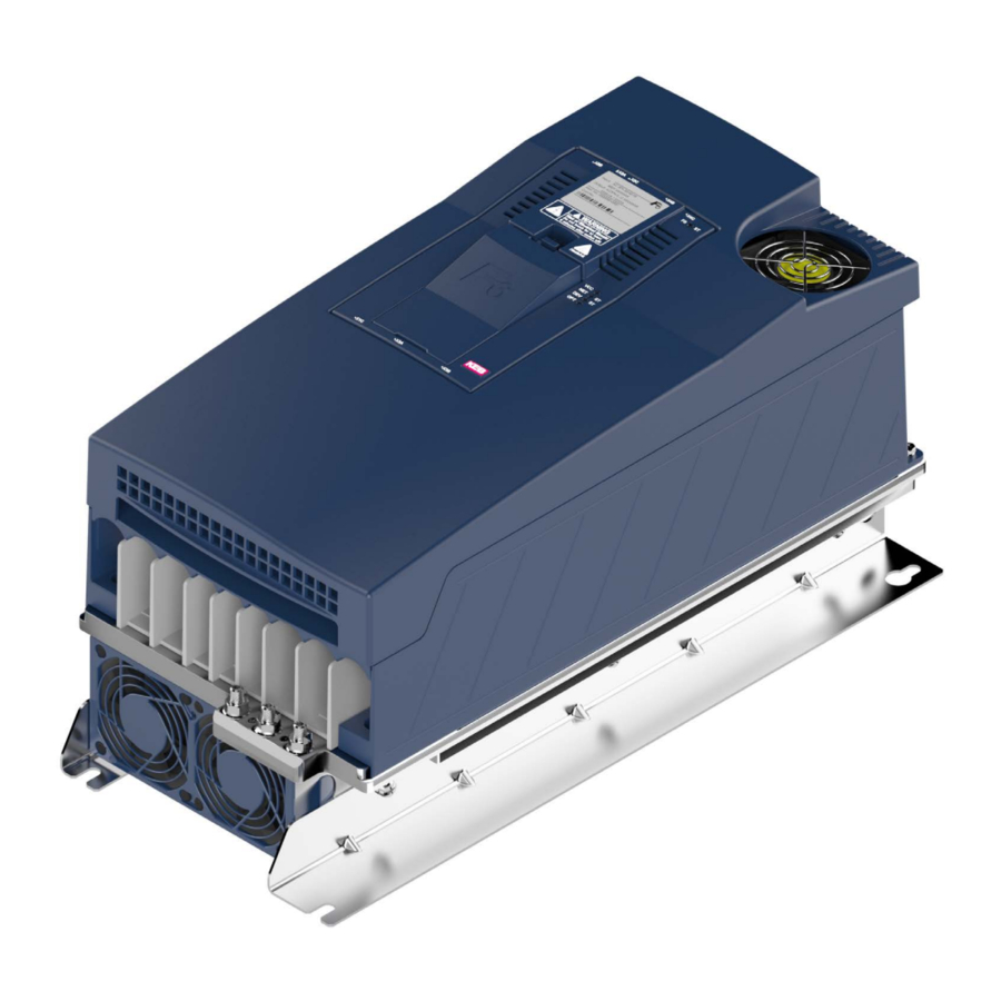
Page 48: Dimensions And Weights
DIMeNSIONS AND WeIGHTS 3.4 Dimensions and weights 3.4.1 built-in version air cooler (24,4) 271,9 für M8 (4x) for M8 (4x) Housing Weight 21.5 kg Dimensions All dimensions in mm Figure 8: Dimensions built-in version air cooler... -
Page 49: Built-In Version Fluid Cooler (Water)
DIMeNSIONS AND WeIGHTS 3.4.2 Built-in version fluid cooler (water) 236,9 (24,5) für M8 (4x) for M8 (4x) Housing 18.1 kg without sub-mounted braking resistors Weight 20 kg without sub-mounted braking resistors Dimensions All dimensions in mm Figure 9: Dimensions built-in version fluid cooler (water) -
Page 50: Push-Through Version Air Cooler Ip20, Ip54-Ready
DIMeNSIONS AND WeIGHTS 3.4.3 Push-through version air cooler IP20, IP54-ready (270,7) für M6 (16x) 179,9 90,8 for M6 (16x) Dichtung gasket 77,5 24,5 für M6 (16x) Ausschnitt for M6 (16x) cut-out (245) Housing Weight 20.6 kg Dimensions All dimensions in mm Figure 10: Dimensions push-through version air cooler IP20, IP54-ready... -
Page 51: Push-Through Version Fluid Cooler (Water) Ip20, Ip54-Ready
DIMeNSIONS AND WeIGHTS 3.4.4 Push-through version fluid cooler (water) IP20, IP54-ready (211,9) für M6 (16x) for M6 (16x) 179,9 77,5 Dichtung 24,5 gasket für M6 (16x) Ausschnitt for M6 (16x) cut-out (245) Housing 17.3 kg without sub-mounted braking resistors Weight 19.2 kg without sub-mounted braking resistors Dimensions All dimensions in mm... -
Page 52: Push-Through Version Fluid Cooler (Oil) Ip20, Ip54-Ready
DIMeNSIONS AND WeIGHTS 3.4.5 Push-through version fluid cooler (oil) IP20, IP54-ready 83,5 31,5 81,5 G 1/2 24,5 für/for M6 R5...R10 ± 1 Housing Weight 21 kg Dimensions All dimensions in mm Figure 12: Dimensions push-through version fluid cooler (oil) IP20, IP54-ready... -
Page 53: Installation Of Ip54-Ready Devices
④ ① IP20 zone ② IP54 zone ③ KEB COMBIVERT ④ Housing (e.g. control cabinet wall) Figure 15: Installation of IP54-ready devices IP54 zone: Heat sink outside the housing The protection class IP54 can only be achieved when the device is properly installed. -
Page 54: Control Cabinet Installation
Use of other mounting material ► The alternatively selected mounting material must comply with the above-mentioned material characteristics (quality) and tightening torques ! The use of other mounting materials is beyond KEB's control and is therefore the sole responsibility of the customer. -
Page 55: Mounting Distances
DIMeNSIONS AND WeIGHTS 3.4.6.2 Mounting distances Power dissipation for the control cabinet dimension „3.2.4 Power dissipation at rated oper- ation“. A lower value can be used here depending on the operating mode/load. Mounting the drive controller For reliable operation, the drive controller must be mounted without any dis- tance on a smooth, closed, metallically bright mounting plate. -
Page 56: Installation And Connection
OVerVIeW OF THe cOMbIVerT F6 4 Installation and connection 4.1 Overview of the cOMbIVerT F6 Housing 6 Name Description Shield clambs for shielded control 1 / 6 cables LEDs (see the manual for control unit chapter "Overview“) • For control card COMPACT: FS without function. -
Page 57: Figure 17: F6 Housing 6 Front View
OVerVIeW OF THe cOMbIVerT F6 Housing 6 Name Description Interior fan Protective earth; at connection to protective earth each terminal may be assigned only once Power circuit terminals for: • Mains input • Braking resistor • DC supply • Motor connection Terminal for: •... -
Page 58: Figure 18: F6 Housing 6 Rear View With Control Board Compact
F6 housing 6 rear view with control board COMPACT Further information can be found in the respective control board manual. Instructions for use COMBIVERT F6 control board COMPACT www.keb.de/fileadmin/media/Manuals/dr/ma_dr_f6-cu-k-inst-20144795_en.pdf Instructions for use COMBIVERT F6 control board APPLICATION www.keb.de/fileadmin/media/Manuals/dr/ma_dr_f6-cu-a-inst-20118593_en.pdf Instructions for use COMBIVERT F6 control board PRO... -
Page 59: Connection Of The Power Unit
cONNecTION OF THe POWer UNIT 4.2 connection of the power unit NOTICE Destruction of the drive controller! ► Never exchange mains input and motor output ! 4.2.1 connection of the voltage supply The COMBIVERT F6 housing 6 can be supplied by mains via terminals L1, L2 and L3. Figure 19: Input circuit Minimum waiting period between two switch-on procedures 5 minutes! -
Page 60: Terminal Block X1A For 400 V Units
cONNecTION OF THe POWer UNIT 4.2.1.1 Terminal block X1A for 400 V units crimp con- Max. num- Terminal connec- Tightening Name Function nector dimen- ber of con- tion torque sion type ductors Mains connection 3-phase For IEC: 2 DC terminals 8 mm stud for 10...15 Nm M8 crimp connec-... -
Page 61: Protective Earth And Function Earth
The use of the functional earth (FE) is not required if the frequency inverter is EMC-technically wired. The functional earth may not be wired green / yellow! Notes on EMC-compatible installation can be found here. www.keb.de/fileadmin/media/Manuals/emv/0000neb0000.pdf... -
Page 62: Ac Mains Connection
Required for compliance with the limit values in accordance with EN 61800-3. HF filter for IT systems ⑥ KEB COMBIVERT Figure 22: Connection of the mains supply 3-phase 4.2.3.2 Supply cable The conductor cross-section of the supply cable is determined by the following factors: •... -
Page 63: Note On Hard Power Systems
cONNecTION OF THe POWer UNIT 4.2.3.3 Note on hard power systems The service life of drive controllers with voltage DC link depends on the DC voltage, am- bient temperature and the current load of the electrolytic capacitors in the DC link. The use of mains chokes can increase the service life of the condensators to a considerable extent, especially when connecting to "hard“... -
Page 64: Dc Connection
OF THe POWer UNIT 4.2.4 Dc connection NOTICE DC operation is only permitted after consultation with KEB! 4.2.4.1 Terminal block X1A DC connection crimp Max. num- Terminal connec- Tightening connector Name Function ber of con- tion torque dimension ductors... -
Page 65: Connection Of The Motor
➁ ➂ ④ Control P A/K Legend ① KEB COMBIVERT Apply motor cable, shielding on both sides over a large surface on the bare metallic frame or mounting ② plate (remove paint if necessary) ③ Three-phase motor ④ Temperature monitoring (optional) =>... -
Page 66: Terminal Block X1A Motor Connection
cONNecTION OF THe POWer UNIT 4.2.5.2 Terminal block X1A motor connection crimp Max. num- Terminal connec- Tightening connector Name Function ber of con- tion torque dimension ductors type For IEC: 2 8 mm stud for 10...15 Nm Motor connection M8 crimp connec- 88...132 lb inch For UL: 2 Figure 25:... -
Page 67: Selection Of The Motor Line
The maximum motor cable length is depending on the capacity of the motor cable as well as on the EMC emitted interference. External measures must be taken here (e.g. the use of a line filter). The following information is valid for the operation under rated conditions and the use of KEB listed filters under chapter „4.3.1 Filters and chokes“. Max. motor cable length shielded in accordance with... -
Page 68: Motor Cable Length For Parallel Operation Of Motors
cONNecTION OF THe POWer UNIT 4.2.5.5 Motor cable length for parallel operation of motors The resulting motor cable length for parallel operation of motors, or parallel installation with multiple cables arises from the following formula: resulting motor cable length = ∑single line length x √Number of motor lines 4.2.5.6 Motor cable cross-section The motor cable cross-section is dependent •... -
Page 69: Connection Of The Temperature Monitoring And Brake Control (X1C)
cONNecTION OF THe POWer UNIT 4.2.5.8 Connection of the temperature monitoring and brake control (X1C) A switchable temperature evaluation is implemented in the COMBIVERT. There are different types for the evaluation available. These are dependending on the control board => instruction manual „control board“. The desired operating mode can be adjusted via software (dr33). If the evaluation is not required, it must be deactivated via software (parameter pn33 = 7) =>... -
Page 70: Figure 29: Connection Of The Brake Control
cONNecTION OF THe POWer UNIT For control board APPLICATION and COMPACT. ➀ ➃ The voltage to the control of a brake is decoupled from the internal voltage supply. The brake works only with external voltage supply. = 24V = 2A For control board PRO _max The brake can be supplied with both, internal and external... -
Page 71: Connection And Use Of A Braking Resistor
► Cover hot surfaces safe-to-touch. ► Before touching, check the surface. ► If necessary, attach warning signs on the system. 4.2.6.1 Installation instructions for side-mounted braking resistors Instructions for the installation of intrinsically safe brak- ing resistors https://www.keb.de/fileadmin/media/Manuals/dr/ma_dr_ Chapter „Installation in- safe-braking-resistors-20106652_en.pdf structions“. -
Page 72: Terminal Block X1A Connection Braking Resistor
cONNecTION OF THe POWer UNIT 4.2.6.2 Terminal block X1A connection braking resistor crimp con- Max. num- Terminal con- Tightening Name Function nector dimen- ber of con- nection torque sion type ductors For IEC: 2 8 mm stud for 10...15 Nm Connection for braking M8 crimp connec- resistor (between + and R) -
Page 73: Use Of Non-Intrinsically Safe Braking Resistors
cONNecTION OF THe POWer UNIT 4.2.6.3 Use of non-intrinsically safe braking resistors WArNING Use of non-intrinsically safe braking resistors Fire or smoke in case of overload or fault ! ► Only use braking resistors with temperature sensor. ► Evaluate temperature sensor. ►... -
Page 74: Accessories
Functional nut for 10 mm tube 0000651-FM10 Table 37: Connections to the coolant 4.3.4 Side-mounted braking resistors Technical data and design about intrinsically safe braking resistors => https://www.keb.de/fileadmin/media/Manuals/dr/ma_dr_ safe-braking-resistors-20106652_en.pdf Technical data and design about non-intrinsically safe braking resistors => https://www.keb.de/fileadmin/media/Manuals/ dr/ma_dr_braking-resistors-20116737_en.pdf... -
Page 75: Installation And Operation Of Liquid-Cooled Devices
WATer-cOOLeD DeVIceS 5 Installation and Operation of Liquid-cooled Devices 5.1 Water-cooled devices The use of water-cooled KEB COMBIVERT drive controllers is offered, because there are process-caused coolants available with some applications. However, the following instructions must be observed. 5.1.1 Heat sink and operating pressure Design system Material max. operating pres- connection... -
Page 76: Requirements For The Coolant
An appropriate antifreeze must be used for applications when the heat sink or the coolant is exposed temperatures below zero. Use only products of one manufac- turer for a better compatibility with other additives. KEB recommends the antifreeze Antifrogen N from Clariant with a maximum vol- ume content of 52 %. Corrosion protection Additives can be used as corrosion protection. -
Page 77: Table 40: Special Requirements For Open And Half-Open Cooling Systems For Water Coolers
WATer-cOOLeD DeVIceS Special requirements for open and half-open cooling systems: requirement Description Impurities Mechanical impurities in half-open cooling systems can be counteracted when ap- propriate water filters are used. Salt concentration The salt content can increase through evaporation at half-open systems. Thus the water is more corrosive. Adding of fresh water and removing of process water works against. -
Page 78: Connection Of The Cooling System
Figure 32: Open pipe ends for the connection of the cooling system for water coolers For the connection of the cooling system KEB recommends the use of functional nuts. Suitable functional nuts are listed in the following chapter => „4.3.3 Connections to the coolant“. -
Page 79: Coolant Temperature And Moisture Condensation
WATer-cOOLeD DeVIceS 5.1.5 coolant temperature and moisture condensation The flow temperature should be selected depending on the volume flow that the heat sink temperature is always 10 K below the overtemperature level (OH) at rated opera- tion. This avoids a sporadic shutdown. The maximum heat sink temperature can be found in chapter => „3.3.1 Switching fre- quency and temperature“. -
Page 80: Permissible Volume Flow With Water Cooling
WATer-cOOLeD DeVIceS Information on coolant management is given in the following document www.keb.de/fileadmin/media/Techinfo/dr/an/ti_dr_an-liquid-cooling-00004_ en.pdf Destruction of the heat sink at storage/transport of water-cooled NOTICE devices! Observe the following points when storing water-cooled devices: ► Completely empty the cooling circuit ► Blow out the cooling circuit with compressed air Destruction of the drive controller due to condensation! ►... -
Page 81: Coolant Heating With Water
WATer-cOOLeD DeVIceS 5.1.7 coolant heating with water Volume flow depending on the total power dissipation and temperature difference be- tween forward flow and return flow. ① ② ③ ④ / kW D_ges Legend Working area ① 5 l/min ② 10 l/min ③ 12.5 l/min ④ 15 l/min Figure 33: Volume flow depending on the total power dissipation PD_ges and temperature difference with water-glycol mixture at rated operation due to overload, higher switching can be higher than the power dissipation P... -
Page 82: Typical Pressure Drop Of The Heat Sink With Water
WATer-cOOLeD DeVIceS 5.1.8 Typical pressure drop of the heat sink with water • The curve characteristic shown below applies to a flow temperature of 25 °C and a glycol content of 52 %. • If higher flow temperatures are used, the pressure drop in the system decreases. • This also applies to cooling media such as water or another glycol mixture • A glycol mixture from Clariant in a ratio of 52 % or 33 % is recommended. 17,5 12,5 q / l /min Legend Working area Figure 34: Typical pressure drop depending on the volume flow... -
Page 83: Oil-Cooled Devices
OIL-cOOLeD DeVIceS 5.2 Oil-cooled devices The following instructions must be observed when using the device. 5.2.1 Heat sink and operating pressure for oil-cooled devices Design system Material max. operating pressure connection => „5.2.3 Connection of Aluminium heat sink Aluminium 3.3206 10 bar the oil cooling system“... -
Page 84: Connection Of The Oil Cooling System
Other elements in the cooling circuit such as pumps, shut-off valves, ventilation etc. must be attached according to the cooling system and the local conditions. ① ② No. connection Type ① Forward flow G 1/2 internal thread ② Return flow Figure 35: Connection of the oil cooling system KEB recommends the use of a flow switch in order to monitor the flow in the cooling system. -
Page 85: Coolant Temperature And Condensation With Oil
OIL-cOOLeD DeVIceS 5.2.4 coolant temperature and condensation with oil The flow temperature should be selected depending on the volume flow that the heat sink temperature is always 10 K below the overtemperature level (OH) at rated opera- tion. This avoids a sporadic shutdown. The maximum heat sink temperature can be found in chapter => „3.3.1 Switching fre- quency and temperature“. -
Page 86: Permissible Volume Flow With Oil
OIL-cOOLeD DeVIceS 5.2.5 Permissible volume flow with oil The volume flow of the following table must be observed. Permissible flow rate Min. flow rate l / min Max. flow rate l / min Table 46: Permissible flow rate for the oil cooler... -
Page 87: Certification
cerTIFIcATION 6 Certification 6.1 ce-Marking CE marked drive controllers were developed and manufactured to comply with the regu- lations of the Low-Voltage Directive and EMC directive. The harmonized standards of the series were used. EN 61800-5-1 EN 61800-3 For further information regarding the CE declarations of conformity =>... -
Page 88: Ul Certification
6.2 UL certification Acceptance according to UL is marked at KEB drive controllers with the adjacent logo on the nameplate. To be conform according to UL for use on the North American and Canadian Market the following additionally instructions must be observed (original text of the UL-File): •... -
Page 89: Further Informations And Documentation
6.3 Further informations and documentation You find supplementary manuals and instructions for the download under www.keb.de/de/service/downloads General instructions • EMC and safety instructions • Manuals for additional control boards, safety modules, fieldbus modules, etc. Instruction and information for construction and development • Input fuses in accordance with UL • Programming manual for control and power unit •... -
Page 90: Revision History
reVISION HISTOry 7 revision History Version Date Description 2016-09 Pre-series 2017-11 Series, new CI, water cooling, UL certification included Corrections of technical drawings, 2018-11 Figures of the overload characteristics adapted 2019-10 Adding of devices with sub-mounted braking resistors 2020-03 Inclusion of the oil-cooled devices 2021-06 Drawings, technical data updated... - Page 91 Tel: +33 149620101 Fax: +33 145767495 c / Mitjer, Nave 8 - Pol. Ind. LA MASIA E-Mail: info@keb.fr Internet: www.keb.fr 08798 Sant Cugat Sesgarrigues (Barcelona) Spain Tel: +34 93 8970268 Fax: +34 93 8992035 E-Mail: vb.espana@keb.de Germany Geared Motors KEB Antriebstechnik GmbH...
- Page 92 Automation with Drive www.keb.de KEB Automation KG Suedstrasse 38 32683 Barntrup Tel. +49 5263 401-0 E-Mail: info@keb.de...
Need help?
Do you have a question about the COMBIVERT F6 Series and is the answer not in the manual?
Questions and answers