KEB COMBIVERT F6 Series Instructions For Use Manual
Installation f6 housing 2
Hide thumbs
Also See for COMBIVERT F6 Series:
- Instructions for use manual (92 pages) ,
- Instruction manual (44 pages) ,
- Instructions for use manual (76 pages)

Related Manuals for KEB COMBIVERT F6 Series


Summary of Contents for KEB COMBIVERT F6 Series
- Page 1 COMBIVERT F6 INSTRUCTIONS FOR USE | INSTALLATION F6 HOUSING 2 Translation of the original manual Document 20099887 EN 07...
-
Page 3: Preface
PreFAce Preface The described hard- and software are developments of the KEB Automation KG. The enclosed documents correspond to conditions valid at printing. Misprint, mistakes and technical changes reserved. Signal words and symbols Certain operations can cause hazards during the installation, operation or thereafter. -
Page 4: Laws And Guidelines
If applicable, the license terms of this software are contained in the instructions for use. The instructions for use are already available to you, can be downloaded free of charge from the KEB website or can be requested from the respec- tive KEB contact person. -
Page 5: Table Of Contents
TAbLe OF cONTeNTS Table of contents Preface ..............................3 Signal words and symbols ......................3 More symbols ..........................3 Laws and guidelines ........................4 Warranty and liability ........................4 Support ............................4 Copyright ............................4 Table of contents ........................... 5 List of Figures ............................8 List of Tables ............................ - Page 6 TAbLe OF cONTeNTS 3.1.4 Electrical operating conditions .................... 28 3.1.4.1 Device classification ......................28 3.1.4.2 Electromagnetic compatibility ..................28 3.2 Device data of the 230 V devices ....................29 3.2.1 Overview of the 230 V devices ................... 29 3.2.2 Voltage and frequencies for 230V devices ................. 30 3.2.2.1 Example of the calculation of the possible motor voltage 230V: ........
- Page 7 TAbLe OF cONTeNTS 4.2.2 Protective earth and function earth ..................64 4.2.2.1 Protective earth ....................... 64 4.2.2.2 Functional earthing ......................64 4.2.3 AC mains connection ......................65 4.2.3.1 AC supply 3-phase ......................65 4.2.3.2 Supply line ........................65 4.2.3.3 Note on hard power systems ................... 66 4.2.4 DC connection ........................
-
Page 8: List Of Figures
LIST OF FIGUreS List of Figures Figure 1: Turn-off time t depending on the overload I/IN at OC level 216 % ........32 Figure 2: Turn-off time t depending on the overload I/IN at OC level 180% ........33 Figure 3: Typical overload characteristics in the lower output frequencies (OL2) example device size 10 ........................35 Figure 4:... -
Page 9: List Of Tables
LIST OF TAbLeS List of Tables Table 1: Part code..........................25 Table 2: Climatic environmental conditions ................... 26 Table 3: Mechanical ambient conditions ..................27 Table 4: Chemical / mechanical active substances ............... 27 Table 5: Device classification......................28 Table 6: Electromagnetic compatibility ..................28 Table 7: Overview of the 230V device data ................... - Page 10 LIST OF FIGUreS Table 43: Max. motor cable length....................69 Table 44: Filters and chokes for 230V devices ................76 Table 45: Filters and chokes for 400V devices ................76 Table 46: Mounting kit shield connection brakets ................76 Table 47: Mounting kit for IP20 devices ...................
-
Page 11: Glossary
Business-to-business IP xx Degree of protection (xx for level) BiSS Open source real-time interface for KEB product The KEB product is subject of this sensors and actuators (DIN 5008) manual Fieldbus system Silicium temperature sensor (pola- Complete drive module including... - Page 12 GLOSSAry Programmable logic controller PT100 Temperature sensor with R0=100Ω PT1000 Temperature sensor with R0=1000Ω PTC-resistor for temperature detec- tion Pulse width modulation RJ45 Modular connector with 8 lines Synchronous sensorless closed loop SELV Safety Extra Low Voltage (< 60 V) The security integrity level is a measure for quantifying the risk reduction.
-
Page 13: Standards For Drive Converters / Control Cabinets
STANDArDS FOr DrIVe cONVerTerS / cONTrOL cAbINeTS Standards for drive converters / control cabinets Product standards that apply directly to the drive converter EN 61800-2 Adjustable speed electrical power drive systems - Part 2: General requirements - Rating specifications for low voltage adjustable frequency a.c. power drive systems (VDE 0160-102, IEC 61800-2) EN 61800-3 Speed-adjustable electrical drives. Part 3: EMC requirements and specific test methods (VDE 0160-103, IEC 61800-3) -
Page 14: Standards That Are Used In The Environment Of The Drive Converter
STANDArDS FOr DrIVe cONVerTerS / cONTrOL cAbINeTS EN 61000-4-5 Electromagnetic compatibility (EMC) - Part 4-5: Testing and measurement techniques - Surge immunity test (IEC 61000-4-5); German version EN 61000-4-5 EN 61000-4-6 Electromagnetic compatibility (EMC) - Part 4-6: Testing and measurement techniques - Immunity to conducted disturbances, induced by radio-frequency fields (IEC 61000-4-6); German version EN 61000-4-6 EN 61000-4-34... -
Page 15: Basic Safety Instructions
► Read the instructions for use ! ► Observe the safety and warning instructions ! ► If anything is unclear, please contact KEB Automation KG ! 1.1 Target group This instruction manual is determined exclusively for electrical personnel. Electrical per- sonnel for the purpose of this instruction manual must have the following qualifications: •... -
Page 16: Installation
bASIc SAFeTy INSTrUcTIONS Drive converters contain electrostatic sensitive components. ► Avoid contact. ► Wear ESD-protective clothing. Do not store drive converters • in the environment of aggressive and/or conductive liquids or gases. • with direct sunlight. • outside the specified environmental conditions. 1.3 Installation DANGer Do not operate in an explosive environment! -
Page 17: Electrical Connection
If personnel protection is required during installation of the system, suitable protective devices must be used for drive converters. www.keb.de/fileadmin/media/Manuals/knowledge/04_techinfo/00_gene- ral/ti_rcd_0400_0002_gbr.pdf Installations which include drive converter shall be equipped with additional control and protective devices in accordance with the relevant applicable safety requirements, e.g. -
Page 18: Emc-Compatible Installation
According to EN 60204-1 it is permissible to disconnect already tested com- ponents. Drive converters of the KEB Automation KG are delivered ex works voltage tested to 100% according to product standard. 1.4.3 Insulation measurement An insulation measurement (in accordance with EN 60204-1 chapter 18.3) with DC... -
Page 19: Start-Up And Operation
If a drive converter with electrolytic capacitors in a DC link (see technical data) has not been in operation for more than one year, observe the following instructions. www.keb.de/fileadmin/media/Manuals/knowledge/04_techinfo/00_gene- ral/ti_format_capacitors_0400_0001_gbr.pdf continuous operation (S1) with load > 60 % or from a rated motor... -
Page 20: Maintenance
For applications that require cyclic switching off and on of the drive converter, maintain an off-time of at least 5 min after the last switch on. If you require shorter cycle times please contact KEB Automation KG. Short-circuit resistance The drive converters are conditional short-circuit proof. After resetting the internal pro- tection devices, the function as directed is guaranteed. -
Page 21: Repair
1.7 Disposal Electronic devices of the KEB Automation KG are exclusively professional devices for further industrial processing (so-called B2B devices). Manufacturers of B2B devices are obliged to take back and recycle devices manufac- tured after 14.08.2018. -
Page 22: Product Description
Technical data and information for connection conditions shall be taken from the type plate and from the instruction manual and must be strictly observed. The used semiconductors and components of the KEB Automation KG are developed and dimensioned for the use in industrial products. -
Page 23: Product Features
PrODUcT DeScrIPTION 2.3 Product features This instruction manual describes the power circuits of the following devices: Device type: Drive converter Series: COMBIVERT F6 Power range: 2.2...7.5 kW / 230 V 4...15 kW / 400 V Housing: The COMBIVERT F6 is characterized by the following features: •... -
Page 24: Part Code
PrODUcT DeScrIPTION 2.4 Part code x x F 6 x x x - x x x x 1: Air-cooler (water), mounted version 2: Liquid cooler (water), mounted version 3: Air-cooler, through-mount version IP54 4: Liquid cooler (water), through-mount version IP54 5: Air-cooler, through-mount version IP20 Liquid cooler (water), trough-mount version IP54, sub- mounted braking resistors... -
Page 25: Table 1: Part Code
PrODUcT DeScrIPTION x x F 6 x x x - x x x x Series COMBIVERT F6 Inverter size 10…33 Table 1: Part code The part code may not be used as order code, but only for identification ! EtherCAT is registered trademark and patented technology, licensed ® by Beckhoff Automation GmbH, Germany CANopen is registered trademark of CAN in AUTOMATION - Interna- ®... -
Page 26: Technical Data
OPerATING cONDITIONS 3 Technical Data Unless otherwise indicated, all electrical data in the following chapter refer to a 3-phase AC mains. 3.1 Operating conditions 3.1.1 climatic environmental conditions Storage Standard class Descriptions Surrounding temperature EN 60721-3-1 -25…55 °C Relative humidity EN 60721-3-1 5…95 % (without condensation) Storage height –... -
Page 27: Mechanical Ambient Conditions
OPerATING cONDITIONS 3.1.2 Mechanical ambient conditions Storage Standard class Descriptions Vibration amplitude 1.5 mm (2…9 Hz) Vibration limits EN 60721-3-1 Acceleration amplitude 5 m/s² (9…200 Hz) Shock limit values EN 60721-3-1 40 m/s²; 22 ms Transport Standard class Descriptions Vibration amplitude 3.5 mm (2…9 Hz) Vibration limits EN 60721-3-2 Acceleration amplitude 10 m/s²... -
Page 28: Electrical Operating Conditions
OPerATING cONDITIONS 3.1.4 electrical operating conditions 3.1.4.1 Device classification requirement Standard class Descriptions – EN 61800-5-1 Overvoltage category EN 60664-1 – Non-conductive pollution, occasional conden- Pollution degree EN 60664-1 sation when PDS is out of service Table 5: Device classification 3.1.4.2 Electromagnetic compatibility For devices without an internal filter, an external filter is required to comply with the following limits. -
Page 29: Device Data Of The 230 V Devices
3.2.1 Overview of the 230 V devices The technical data are for 2/4-pole standard motors. With other pole numbers the drive converter must be dimensioned onto the rated motor current. Contact KEB for special or medium frequency motors. Device size... -
Page 30: Voltage And Frequencies For 230V Devices
DeVIce DATA OF THe 230 V DeVIceS Device size Housing Protection function for braking transistor No protection function available (GTR7) Insulating resistance @ U = 500V / MΩ > 20 Table 7: Overview of the 230V device data The values refer in % to the rated output current I The output frequency is to be limited in such a way that it does not exceed 1/10 of the switching frequency. -
Page 31: Example Of The Calculation Of The Possible Motor Voltage 230V
DeVIce DATA OF THe 230 V DeVIceS 3.2.2.1 Example of the calculation of the possible motor voltage 230V: The motor voltage for dimensioning of the drive is depending on the used components. The motor voltage reduces according to the following table: Component Reduction / % Example... -
Page 32: Overload Characteristic (Ol) For 230 V Devices
DeVIce DATA OF THe 230 V DeVIceS 3.2.3.1 Overload characteristic (OL) for 230 V devices All drive converters with overload characteristic of 180 % or 216 % can be operated at rated switching frequency with an utilization of 150 % for 60 s. Restrictions: •... -
Page 33: Figure 2: Turn-Off Time T Depending On The Overload I/In At Oc Level 180
DeVIce DATA OF THe 230 V DeVIceS Overload characteristic (OC level 180%) ① ② Motor current / drive converter rated currrent / % Legend ① Thermal overload limit ② Limitation by the software current limit (the limit can be set with parameter is35) Figure 2: Turn-off time t depending on the overload I/IN at OC level 180% •... -
Page 34: Frequency-Dependent Maximum Current (Ol2) For 230V Devices
DeVIce DATA OF THe 230 V DeVIceS 3.2.3.2 Frequency-dependent maximum current (OL2) for 230V devices The characteristics of the maximum currents for a switching frequency which are de- pending on the output frequency are different for each drive converter, but the following rules are generally applicable: •... -
Page 35: Figure 3: Typical Overload Characteristics In The Lower Output Frequencies (Ol2) Example
DeVIce DATA OF THe 230 V DeVIceS The following characteristic curve indicates the permissible maximum current for the out- put frequency values 0 Hz, 3.1 Hz, 6.2 Hz, 12.5 Hz, 25 Hz and 50 Hz. Device size 10 is shown as an example. Output frequency / Hz Legend Overcurrent I... -
Page 36: Table 14: Frequency-Dependent Maximum Current For Device Size 10
DeVIce DATA OF THe 230 V DeVIceS The values for the respective device size are listed in the following tables. Frequency-dependent maximum current Device size rated switching frequency 8 kHz Output frequency / Hz 12.5 2 kHz 4 kHz Frequency-dependent maximum current @ f 8 kHz Basic Time Period = 62.5 µs (Parameter is22=0) 16 kHz... -
Page 37: Table 15: Frequency-Dependent Maximum Current For Device Size 12
DeVIce DATA OF THe 230 V DeVIceS Device size rated switching frequency 4 kHz Output frequency / Hz 12.5 2 kHz 4 kHz Frequency-dependent maximum current @ f 8 kHz Basic Time Period = 62.5 µs (Parameter is22=0) 16 kHz 1.75 kHz 3.5 kHz Frequency-dependent maximum current @ f... -
Page 38: Power Dissipation At Rated Operation Of The 230V Devices
DeVIce DATA OF THe 230 V DeVIceS Device size rated switching frequency 4 kHz Output frequency / Hz 12.5 2 kHz 4 kHz Frequency-dependent maximum current @ f 8 kHz Basic Time Period = 62.5 µs (Parameter is22=0) 16 kHz 1.75 kHz 3.5 kHz Frequency-dependent maximum current @ f... -
Page 39: Device Data Of The 400 V Devices
3.3.1 Overview of the 400 V devices The technical data are for 2/4-pole standard motors. With other pole numbers the drive converter must be dimensioned onto the rated motor current. Contact KEB for special or medium frequency motors. Device size... -
Page 40: Voltage And Frequencies For 400V Devices
DeVIce DATA OF THe 400 V DeVIceS Device size Housing Protection function for braking transis- No protection function available tor (GTR7) Insulation resistance @ U = 500 V / MΩ > 20 Table 20: Overview of the 400V device data The values refer in % to the rated output current I The output frequency is to be limited in such a way that it does not exceed 1/10 of the switching frequency. -
Page 41: Example Of The Calculation Of The Possible Motor Voltage
DeVIce DATA OF THe 400 V DeVIceS 3.3.2.1 Example of the calculation of the possible motor voltage: The motor voltage for dimensioning of the drive is depending on the used components. The motor voltage reduces according to the following table: component reduction / % example... -
Page 42: Overload Characteristic (Ol) For 400 V Devices
DeVIce DATA OF THe 400 V DeVIceS 3.3.3.1 Overload characteristic (OL) for 400 V devices All drive converters with overload characteristic of 180 % or 216 % can be operated at rated switching frequency with an utilization of 150 % for 60 s. Restrictions: •... -
Page 43: Figure 5: Turn-Off Time T Depending On The Overload I/In At Oc Level 180
DeVIce DATA OF THe 400 V DeVIceS Overload characteristic (OC level 180%) ① ② Motor current / drive converter rated currrent / % Legend ① Thermal overload limit ② Limitation by the software current limit (the limit can be set with parameter is35) Figure 5: Turn-off time t depending on the overload I/IN at OC level 180% •... -
Page 44: Frequency-Dependent Maximum Current (Ol2) For 400V Devices
DeVIce DATA OF THe 400 V DeVIceS 3.3.3.2 Frequency-dependent maximum current (OL2) for 400V devices The characteristics of the maximum currents for a switching frequency which are de- pending on the output frequency are different for each drive converter, but the following rules are generally applicable: •... -
Page 45: Figure 6: Typical Overload Characteristics In The Lower Output Frequencies (Ol2) Example
DeVIce DATA OF THe 400 V DeVIceS The following characteristic curve indicates the permissible maximum current for the output frequency values 0 Hz, 3.1 Hz, 6.2 Hz, 12.5 Hz, 25 Hz and 50 Hz. Device size 15 is shown as an example. Output frequency / Hz Legend Overcurrent I... -
Page 46: Table 27: Frequency-Dependent Maximum Current For Device Size 12
DeVIce DATA OF THe 400 V DeVIceS The values for the respective device size are listed in the following tables. Frequency-dependent maximum current Device size rated switching frequency 8 kHz Output frequency / Hz 12.5 2 kHz 4 kHz Frequency-dependent maximum current @ f 8 kHz Basic Time Period = 62.5 µs (Parameter is22=0) 16 kHz... -
Page 47: Table 29: Frequency-Dependent Maximum Current For Device Size 14
DeVIce DATA OF THe 400 V DeVIceS Device size rated switching frequency 4 kHz Output frequency / Hz 12.5 2 kHz 4 kHz Frequency-dependent maximum current @ f 8 kHz Basic Time Period = 62.5 µs (Parameter is22=0) 16 kHz 1.75 kHz 3.5 kHz Frequency-dependent maximum current @ f... -
Page 48: Table 31: Frequency-Dependent Maximum Current For Device Size 16 (2 Khz)
DeVIce DATA OF THe 400 V DeVIceS Device size rated switching frequency 2 kHz Output frequency / Hz 12.5 2 kHz 4 kHz Frequency-dependent maximum current @ f 8 kHz Basic Time Period = 62.5 µs (Parameter is22=0) 16 kHz 1.75 kHz 3.5 kHz Frequency-dependent maximum current @ f... -
Page 49: Power Dissipation At Rated Operation Of The 400 V Devices
DeVIce DATA OF THe 400 V DeVIceS 3.3.4 Power dissipation at rated operation of the 400 V devices Device size Rated switching frequency Power dissipation at rated operation Table 33: Power dissipation of the 400 V devices Rated operation corresponds to U = 400 V;... -
Page 50: General Electrical Data
GeNerAL eLecTrIcAL DATA 3.4 General electrical data 3.4.1 Switching frequency and temperature of the 230 V devices Device size Rated switching frequency / kHz Max. switching frequency / kHz S_max Min. switching frequency / kHz S_min Max. heat sink temperature / °C Temperature for derating the switching frequency / °C... -
Page 51: Dc Link / Braking Transistor Function (Gtr7)
GeNerAL eLecTrIcAL DATA 3.4.3 Dc link / braking transistor function (GTr7) Destruction of the drive converter if the value falls below the NOTICE minimum brake resistance value ► The minimum brake resistance value must not fall below! DC link Inverter Motor Rectifier Braking... -
Page 52: Dc Link / Braking Transistor Function Of The 400 V Devices
GeNerAL eLecTrIcAL DATA 3.4.3.2 DC link / braking transistor function of the 400 V devices Device size DC link rated voltage @ U = 400 V N_dc DC link rated voltage @ U = 480 V N_UL N_dc_UL DC link voltage working voltage range 390...780 IN_dc DC switch-off level „Error! Underpotential“... -
Page 53: Switching Behaviour Of The Fans
GeNerAL eLecTrIcAL DATA 3.4.4.1 Switching behaviour of the fans The fans have different switch-on and switch-off points. The switching point for the switch-on temperature ① is adjustable. The hysteresis for the switch-off temperature ② cannot be changed. The switching behaviour of the fans depends on the heat sink and interior temperature. -
Page 54: Dimensions And Weights
DIMeNSIONS AND WeIGHTS 3.5 Dimensions and weights 3.5.1 built-in version air cooler Housing Weight 5 kg Dimensions All dimensions in mm Optional shield connection braket Figure 9: Dimensions built-in version air cooler... -
Page 55: Push-Through Version Ip20
DIMeNSIONS AND WeIGHTS 3.5.2 Push-through version IP20 24,5 Housing Weight 5.2 kg Dimensions All dimensions in mm Optional shield connection braket Figure 10: Dimensions push-through version IP20 Optional push-through frame for the IP20 push-through version: 00F6V80-2004. Further information => „Mounting kit push-through frame for IP20 devices“. -
Page 56: Push-Through Version Ip54
DIMeNSIONS AND WeIGHTS 3.5.3 Push-through version IP54 77,5 77,5 Housing Weight 5.2 kg Dimensions All dimensions in mm Optional shield connection braket Figure 11: Dimensions push-through version IP54 IP54 zone: Heat sink underneath the mounting plate For proper installation, the enclosed seal (20F6T45-0001) must be installed between heat sink and housing (e.g. -
Page 57: Control Cabinet Installation
DIMeNSIONS AND WeIGHTS 3.5.4 control cabinet installation 3.5.4.1 Mounting instructions The following mounting materials with the appropriate quality must be used to mount the drive converter. required material Tightening torque 6.5 Nm Socket screw ISO 4762 - M6 - 8.8 58 lb inch ―... -
Page 58: Figure 13: Control Cabinet Ventilation
DIMeNSIONS AND WeIGHTS Front and side view of the coolant inlet Direction of the airflow Coolant outlet Coolant inlet Figure 13: Control cabinet ventilation... -
Page 59: Installation And Connection
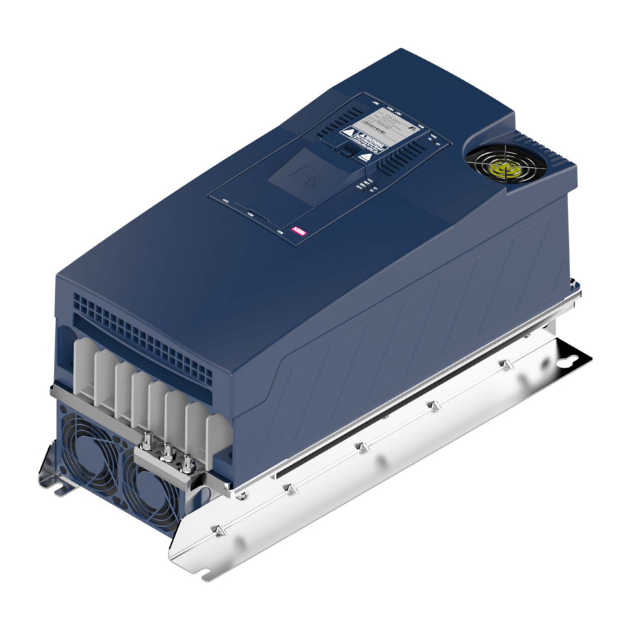
OVerVIeW OF THe cOMbIVerT F6 4 Installation and connection 4.1 Overview of the cOMbIVerT F6 Housing 2 Name Description Fixing points for the optional shielding plates. The shielding e.g. from the motor cable is laid on the mounting plate in the control cabinet or on the shielding plates (optionally available). -
Page 60: Figure 15: F6 Housing 2 Front View
OVerVIeW OF THe cOMbIVerT F6 Housing 2 Name Description Power circuit terminals for: • Mains input • Braking resistor • DC supply • Motor connection Protective earth; at connection to protective earth each terminal may be assigned only once. Fixing points for the optional shielding plates. -
Page 61: Figure 16: F6 Housing 2 Rear View With Control Board Application
F6 housing 2 Rear view with control board APPLICATION Further views can be found in the respective control board manual. Instructions for use COMBIVERT F6 control board APPLICATION www.keb.de/fileadmin/media/Manuals/dr/ma_dr_f6-cu-a-inst-20118593_en.pdf Instructions for use COMBIVERT F6 control board COMPACT www.keb.de/fileadmin/media/Manuals/dr/ma_dr_f6-cu-k-inst-20144795_en.pdf Instructions for use COMBIVERT F6 control board PRO... -
Page 62: Connection Of The Power Unit
cONNecTION OF THe POWer UNIT 4.2 connection of the power unit NOTICE Destruction of the drive converter! ► Never exchange mains input and motor output! 4.2.1 connection of the voltage supply The COMBIVERT F6 housing 2 can be supplied from the mains. The starting current limiting is ar- ranged before the DC link. -
Page 63: Terminal Block X1A
cONNecTION OF THe POWer UNIT 4.2.1.1 Terminal block X1A Tightening Max. number Name Function cross-section for terminal connection torque of conductors Mains connection 3-phase Flexible line with wire-end ferrule with DC terminals plastic collars 2.5...10 mm² For IEC: 2 For 2 conductors 0.5mm...1.5mm² 1.5 Nm Connection for brak- 13 Ib inch... -
Page 64: Protective Earth And Function Earth
The use of the functional earth (FE) is not required if the frequency inverter is EMC-technically wired as described in the manual => Before starting. The functional earth may not be wired green / yellow! Notes on EMC-compatible installation can be found here. www.keb.de/fileadmin/media/Manuals/emv/0000neb0000.pdf... -
Page 65: Ac Mains Connection
Required for compliance with the limit values in accordance with EN 61800-3. HF filter for IT systems ⑥ KEB COMBIVERT Figure 20: Connection of the mains supply 3-phase 4.2.3.2 Supply line The conductor cross-section of the supply line is determined by the following factors: •... -
Page 66: Note On Hard Power Systems
cONNecTION OF THe POWer UNIT 4.2.3.3 Note on hard power systems The service life of drive converters with voltage DC link depends on the DC voltage, surrounding temperature and the current load of the electrolytic capacitors in the DC link. The use of mains chokes can increase the service life of the condensators to a con- siderable extent, especially when connecting to „hard“... -
Page 67: Dc Connection
OF THe POWer UNIT 4.2.4 Dc connection NOTICE Dc operation ► DC operation is only permitted after consultation with KEB! 4.2.4.1 Terminal block X1A DC connection Tightening Max. number Name Function cross-section for terminal connection torque of conductors Flexible line with wire-end ferrule with plastic collars 2.5...10 mm²... -
Page 68: Connection Of The Motor
➁ ➂ ④ Control P A/K Legend ① KEB COMBIVERT Apply motor cable, shielding on both sides over a large surface on the bare metallic frame or mounting ② plate (remove paint if necessary) ③ Three-phase motor ④ Temperature monitoring (optional) =>... -
Page 69: Selection Of The Motor Line
The maximum motor cable length is depending on the capacity of the motor cable as well as on the EMC emitted interference. External measures must be taken here (e.g. the use of a line filter). The following information is valid for the operation under rated conditions and the use of KEB listed filters under chapter => „Filters and chokes“ ! Max. motor cable length shielded in accordance with EN 61800-3 max. -
Page 70: Motor Cable Length For Parallel Operation Of Motors
cONNecTION OF THe POWer UNIT 4.2.5.5 Motor cable length for parallel operation of motors The resulting motor cable length for parallel operation of motors, or parallel installation with multiple cables arises from the following formula: resulting motor cable length = ∑single line length x √Number of motor lines 4.2.5.6 Motor cable cross-section The motor cable cross-section is dependent •... -
Page 71: Connection Of The Temperature Monitoring And Brake Control (X1C)
cONNecTION OF THe POWer UNIT 4.2.5.8 Connection of the temperature monitoring and brake control (X1C) A switchable temperature evaluation is implemented in the COMBIVERT. There are different types for the evaluation available. These are dependending on the control board => instruction manual „control board“... -
Page 72: Figure 27: Connection Of The Brake Control
cONNecTION OF THe POWer UNIT NOTICE Malfunctions due to incorrect line or laying! Malfunctions of the control due to capacitive or inductive coupling. ► Do not route cables from the motor temperature sensor (also shiel- ded) together with control cables. ►... -
Page 73: Connection And Use Of A Braking Resistor
► Cover hot surfaces safe-to-touch. ► Before touching, check the surface. ► If necessary, attach warning signs on the system. 4.2.6.1 Installation instructions for side-mounted braking resistors Instructions for the installation of intrinsically safe brak- ing resistors https://www.keb.de/fileadmin/media/Manuals/dr/ma_dr_ Chapter „Installation in- safe-braking-resistors-20106652_en.pdf structions“. -
Page 74: Terminal Block X1A Connection Braking Resistor
cONNecTION OF THe POWer UNIT 4.2.6.2 Terminal block X1A connection braking resistor Tightening Max. number Name Function cross-section for terminal connection torque of conductors Flexible line with wire-end ferrule with plastic collars 2.5...10 mm² For IEC: 2 Connection for For 2 conductors 0.5mm...1.5mm² 1.5 Nm braking resistor 13 Ib inch... -
Page 75: Wiring Of An Intrinsically Safe Braking Resistor
Intrinsically safe braking resisitors behave in error case such as a safety fuse. They interrupt themselves without fire risk. More information about intrinsically safe braking resistors www.keb.de/fileadmin/media/Manuals/dr/ma_dr_safe-braking-resis- tors-20106652_en.pdf 4.2.6.4 Using a non-intrinsically safe braking resistor Using a non-intrinsically safe braking resistor with extend- ed temperature monitoring www.keb.de/fileadmin/media/Manuals/dr/ma_dr_braking-resis-... -
Page 76: Accessories
AcceSSOrIeS 4.3 Accessories 4.3.1 Filters and chokes Voltage class Drive converter size HF filter Mains choke 50 Hz / 4 % U 14E6T601050 10Z1B031000 14E6T601050 12Z1B031000 230 V 16E6T601050 13Z1B031000 16E6T601050 14Z1B031000 Table 44: Filters and chokes for 230V devices Voltage class Drive converter size HF filter... -
Page 77: Side-Mounted Braking Resistors
AcceSSOrIeS 4.3.4 Side-mounted braking resistors Technical data and design about intrinsically safe braking resistors => https://www.keb.de/fileadmin/media/Manuals/dr/ma_dr_ safe-braking-resistors-20106652_en.pdf Technical data and design about non-intrinsically safe braking resistors => https://www.keb.de/fileadmin/media/Manuals/ dr/ma_dr_braking-resistors-20116737_en.pdf... -
Page 78: Certification
cerTIFIcATION 5 Certification 5.1 ce-Marking CE marked drive converters were developed and manufactured to comply with the reg- ulations of the Low-Voltage Directive and EMC directive. The harmonized standards of the series EN 61800-5-1 EN 61800-3 were used. For further information regarding the CE declarations of conformity =>... -
Page 79: Ul Certification
5.2 UL certification Acceptance according to UL is marked at KEB drive converters with the adjacent logo on the nameplate. To be conform according to UL for use on the North American and Canadian Market the following additionally instructions must be observed (original text of the UL-File): •... -
Page 80: Further Informations And Documentation
5.3 Further informations and documentation You find supplementary manuals and instructions for the download under www.keb.de/de/service/downloads General instructions • EMC and safety instructions • Manuals for additional control boards, safety modules, fieldbus modules, etc. Instruction and information for construction and development • Input fuses in accordance with UL • Programming manual for control and power unit •... -
Page 81: Revision History
reVISION HISTOry 6 revision History Version Date Description 2015-10 Prototype 2016-04 Pre-series 2016-08 Pre-series (without UL certification) 2016-11 UL certified terminal X1A included Series version, 4kHz devices included (device size 16), new CI, UL certification 2017-02 included 2018-05 Corrections to the technical data figures of the overload characteristics adapted 2019-11 Switching performance of fans added, data of overload characteristics adapted. 2020-01 Inclusion of the 230V devices... - Page 82 NOTES...
- Page 83 CEP 13569-430 Portal do Sol, São Carlos Brazil Gangnam Gu 135- 757 Seoul Republic of Korea Tel: +55 16 31161294 E-Mail: roberto.arias@keb.de Tel: +82 2 6253 6771 Fax: +82 2 6253 6770 E-Mail: vb.korea@keb.de KEB Automation GmbH czech republic KEB RUS Ltd.
- Page 84 Automation with Drive www.keb.de KEB Automation KG Suedstrasse 38 32683 Barntrup Tel. +49 5263 401-0 E-Mail: info@keb.de...
Need help?
Do you have a question about the COMBIVERT F6 Series and is the answer not in the manual?
Questions and answers