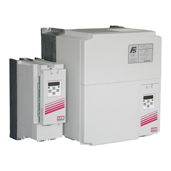
KEB COMBIVERT F5 Series Instruction Manual
Hide thumbs
Also See for COMBIVERT F5 Series:
- Instruction manual (116 pages) ,
- Instructions for use manual (72 pages) ,
- Installation manual (46 pages)

Related Manuals for KEB COMBIVERT F5 Series


Summary of Contents for KEB COMBIVERT F5 Series
- Page 1 COMBIVERT GB INSTRUCTION MANUAL Power Circuit Housing H 11...18.5 kW 230 V 11...37 kW 400 V Original manual Mat.No. Rev. 00F50EB-KH00...
-
Page 3: Table Of Contents
Table of Contents Preface ......................5 General ..........................5 Safety Instructions ......................5 Validity and liability ......................5 Copyright ..........................6 1.5 Specified application ......................6 Product description ......................7 Part code ..........................8 Installation instructions ...................... 9 1.8.1 Cooling systems ........................9 1.8.2 Control cabinet installation .................... - Page 4 Table of Contents Annex B ........................35 B.1 Certification ........................35 B.1.1 CE Marking .......................... 35 B.1.2 UL Marking........................... 35 Annex C ........................37 Installation of water-cooled units ..................37 C.1.1 Heat sink and operating pressure ..................37 C.1.2 Materials in the cooling circuit ....................37 C.1.3 Requirements on the coolant ....................
-
Page 5: Preface
EMC and operating instructions (part 1 operating instruc- „Getting Started“ 0000NEB-0000). This instruction is provi- tions ded with the unit or by download of www.keb.de. Non-observance of the safety instructions leads to the loss of any liability claims. The safety and warning instructions specified in this manual do not lay claim on completeness. This list is not exhaustive. -
Page 6: Copyright
The used semiconductors and components of KEB are developed and dimensioned for the use in industrial products. If the KEB COMBIVERT is used in machines, which work under exceptional conditions or if essential functions, life-supporting measures or an extraordinary safety step must be fulfilled, the necessary reliability and security must be ensured by the machine builder. -
Page 7: Product Description
Preface Product description This instruction manual describes the power circuits of the following units: Unit type: Frequency inverter Series: COMBIVERT F5/F6 Power range: 11…18.5 kW / 230 V class 11…37 kW / 400 V class Housing size: Features of the power circuits : •... -
Page 8: Part Code
Preface Part code 18 . F5 . K 1 H-3 6 0 F Cooling 0, 5, A, F heat sink (standard) 1, B, G Flat rear 2, C, H Water cooling 3, D, I convection Encoder interface 0: none Switching frequency; short time current limit; overcurrent limit 2 kHz;... -
Page 9: Installation Instructions
General Installation instructions 1.8.1 Cooling systems The KEB COMBIVERT is available for different cooling systems: Heat sink with cooling fan (mounted version) The standard version is delivered with heat sink and cooling fan. Special versions The dissipation of power loss must be guaranteed by the machine builder. -
Page 10: Control Cabinet Installation
General 1.8.2 Control cabinet installation Mounting distances Dimensi- Distance in mm Distance in inch 1) Distance to preceding elements in the cabinet door. Direction of the Front and side view of the coolant inlet cooling fins Coolant outlet Coolant inlet See Annex C for instructions of water-cooled units. -
Page 11: Safety And Operating Instructions
Safety Instructions Safety and operating instructions Safety and operating instructions for drive converters (in conformity with the Low-Voltage Directive 2006/95/EC) 1. General 4. Installation In operation, drive converters, depending on their degree The installation and cooling of the appliances shall be in of protection, may have live, uninsulated, and possibly accordance with the specifications in the pertinent docu- also moving or rotating parts, as well as hot surfaces. -
Page 12: Technical Data
Technical Data Technical Data Operating conditions Standard Standard/ Instructions class EN 61800-2 Inverter product standard: rated specifications Definition acc. Inverter product standard: general safety EN 61800-5-1 max. 2000 m above sea level Site altitude With site altitudes over 1000 m a derating of 1 % per 100 m must be taken into consideration. -
Page 13: Technical Data Of The 230V Class
The output frequency is to be limited in such way that 1/10 of the switching frequency is not exceeded The technical data are for 2/4-pole standard motors. With other pole numbers the inverter must be dimensioned onto the motor rated current. Contact KEB for special or medium fre- quency motors. -
Page 14: Technical Data Of The 400 V Class
11) The output frequency is to be limited in such way that 1/10 of the switching frequency is not exceeded The technical data are for 2-/4-pole standard motors. With other pole numbers the inverter must be dimensioned onto the motor rated current. Contact KEB for special or medium fre- quency motors. -
Page 15: Dc Supply
Technical Data of the 400 V Class No braking resistor may be connected for control type "Basic" at an input rated vol- tage of 480 Vac. The response threshold of the braking transistor (Pn.69) for all other controls without safety technology (A, E, G, H, M) must be adjusted at least to 770 Vdc (see annex D). -
Page 16: Dimensions And Weights
Technical Data - Dimensions and Weights Dimensions and Weights Dimensions mounted version air-cooled START ENTER FUNC. SPEED STOP COMBIVERT Weight: 14 kg GB - 16... - Page 17 Technical Data - Dimensions and Weights Dimensions through-mount version air-cooled 76,5 1) Metal holder with shielding clamp optional 2) Cabinet outcut Weight: 22 kg GB - 17...
- Page 18 Technical Data - Dimensions and Weights Dimensions mounted version water-cooled G1/2 DIN 2999/1 Weight: 32 kg GB - 18...
- Page 19 Technical Data - Dimensions and Weights Dimensions through-mount version water-cooled 307±1 G1/2 1) Metal holder with shielding clamp optional 2) Cabinet outcut Weight: 31 kg GB - 19...
- Page 20 Technical Data - Dimensions and Weights Dimensions through-mount version water-cooled with sub-mounted braking resistor 307±1 G1/2 220,5 1) Metal holder with shielding clamp optional 2) Cabinet outcut Weight: 33 kg GB - 20...
-
Page 21: Terminal Strips Of The Power Circuit
Connection Terminals Terminal strips of the power circuit Observe input voltage, since 230 V and 400 V classes are possible All terminal blocks meet the requirements on EN 60947-7-1 (IEC 60947-7-1) Housing size H Name Function Terminal (2.6.1) L1, L2, L3 3-phase mains connection U, V, W Motor connection ++, PB... -
Page 22: Accessories
Accessories Accessories 2.7.1 Filter and chokes Voltage class Inverter Filter Mains choke 50 Hz Motor choke 100 Hz size (4 % Uk) (4 % Uk) 18E5T60-1002 15Z1B03-1000 15Z1F04-1010 18E6T60-3000 19E5T60-1002 230 V 16Z1B03-1000 16Z1F04-1010 20E6T60-3000 20E5T60-1002 16Z1B03-1000 17Z1F04-1010 20E6T60-3000 Voltage class Inverter Filter Mains choke 50 Hz... - Page 23 Accessories E6 (side-mounted) 16E6T60-3000 18/20E6T60-3000 Weight [kg] A [mm] B [mm] Weight [kg] 1.65 18E6T60-3000 20E6T60-3000 GB - 23...
-
Page 24: Technical Data Mains And Motor Choke
Accessories 2.7.3 Technical data mains and motor choke Weight Dimensions [mm] Mat.-number PE Terminal H1 L1 [kg] Mains choke 230 V 15Z1B03-1000 0.335 50.4 90 178 167 95 – 166 – 8 M4 16 mm 16Z1B03-1000 0.243 69.5 110 219 200 110 – 201 – 12 M6 16 mm 17Z1B03-1000 0.191 88.2 125 219 214 130 –... -
Page 25: Connection Power Unit
Connection Power Unit 2.8.1 Mains and motor connection Absolutely pay attention to the supply voltage of the KEB COMBIVERT. A 230 V unit at 400 V mains is destroyed immediately. Exchanging mains and motor connection leads to immediate destruction of the unit. -
Page 26: Selection Of The Motor Cable
Connection Power Unit 2.8.2 Selection of the motor cable Correct selection and wiring of the motor cable is very important: • lower abrasion of the motor bearings by leakage currents • improved EMC characteristics • lower symmetrical operating capacities • less losses by transient currents 2.8.3 Connection of the motor As a standard the connection of the motor must be carried out in accordance with the fol-... -
Page 27: Temperature Detection T1, T2
Parameter In.17 displays in high byte the installed temperature input of the inverter. The KEB COMBIVERT F5/F6 is delivered as standard with switchable PTC/KTY evaluation. The desired function is adjusted with Pn.72 (dr33 at F6) and operates in accordance with the fol- lowing table: In.17 Function of T1,... -
Page 28: 2.7.4.1 Use Of The Temperature Input In Kty Mode
Connection Power Unit 2.7.4.1 Use of the temperature input in KTY mode Connection of a KTY sensor KTY sensors are poled semiconductors and must be operated in forward direction! Connect anode to T1 ! Non-observance leads incorrect measurement in the upper temperature range. -
Page 29: Connection Of A Braking Resistor
Connection Power Unit 2.7.5 Connection of a braking resistor Braking resistors dissipate the produced energy of the motor into heat during generatoric operation. Thus braking resistors can cause very high surface tem- peratures. During assembly pay attention to appropriate protection against con- tact and fire. -
Page 30: Braking Resistor With Over-Heat Protection And Gtr7 Monitoring (Water-Cooled Inverters)
Connection Power Unit 2.7.5.2 Braking resistor with over-heat protection and GTR7 monitoring (water-cooled invert- ers) This circuit offers a direct protection with defective GTR7 (braking transistor). At defective braking transistor an integrated relay opens the terminals K1/K2 and error „E.Pu“ is released. Terminals K1/K2 are integrated into the holding circuit of the input contactor, so the input volt- age is switched off in error case. -
Page 31: Braking Resistor With Over-Heat Protection And Gtr7 Monitoring (Air-Cooled Inverters)
Connection Power Unit 2.7.5.3 Braking resistor with over-heat protection and GTR7 monitoring (air-cooled inverters) This circuit offers a direct protection with defective GTR7 (braking transistor). The braking resistor overheats and opens the OH terminals with defective GTR7. The OH terminals open the holding circuit of the input contactor, so that the input voltage is switched off in error case. -
Page 32: Annex A
Annex Annex A Overload characteristic Time [s] Load [%] 105 110 115 120 125 130 135 140 145 150 160 170 180 190 200 210 220 The characteristic declines device-dependently in this range (see unit identification). On exceeding a load of 105% the overload integrator starts. When falling below the integrator counts backwards. -
Page 33: Calculation Of The Motor Voltage
Due to the leakage current the oxide layer is unrenewed. If the capacitor starts running with rated voltage there is a high leakage current which can destroy the capacitor. In order to avoid defectives, the KEB COMBIVERT must be started up depending on the sto- rage period in accordance with the following specification: Storage period <... -
Page 34: Cooling Circuit
• Input voltages as before, however double the times per year. Eventually change capaci- tors Eventually change capacitors. After expiration of this start-up the KEB COMBIVERT can be operated on nominal rating con- ditions or delivered to a new storage. -
Page 35: Annex B
• Overload protection at 130 % of inverter output rated current (see type plate) • “Cooling medium max. Pressure rating of 10 bar (145 PSI)” • For KEB Control boards type „Basic (B)“ or „Compact (C)“ motor overload protection has to be added by using the internal motor thermal sensor. - Page 36 Annex Short Circuit rating F5/F6 housing H: 240V Models: “Suitable For Use On A Circuit Capable Of Delivering Not More Than 18000 rms Symmetrical Amperes, 240 Volts Maximum When Protected by Class RK5 Fuses. See instructional manual for maximum fuse sizes” 480V Models: “Suitable For Use On A Circuit Capable Of Delivering Not More Than 18000 rms Symmetrical Amperes, 480 Volts Maximum When Protected by Class RK5 Fuses.
-
Page 37: Annex C
This has positive effects on lifetime-relevant components such as fan and DC link circuit capacitors and power modules (IGBT). Also the temperature dependent switching losses are positively effected. The use of water-cooled KEB COMBIVERT frequen- cy inverters is offered in the drive technology, because there are process-caused coolants available with some applications. -
Page 38: Requirements On The Coolant
Annex Table 1.5.2 Electro-chemical voltage series / standard potentials against hydrogen Material generated Ion Standard po- Material generated Ion Standard po- tential tential Aluminium -1.67 V Copper 0.34 V Manganese -1.05 V Carbon 0.74 V Zinc -0.76 V Silver 0.80 V Chrome -0.71 V Platinum... -
Page 39: Connection To The Cooling System
• Pay attention to flux direction and check tightness ! • The cooling flow must always be started before starting the KEB COMBIVERT. The connection to the cooling system can occur as closed or open cooling circuit. The con- nection to a closed cycle cooling circuit is recommended, because the danger of contaminati- on of coolant is very small. - Page 40 Annex Supply of temper coolant This is possible by using heatings in the cooling circuit for the control of the coolant tempera- ture. The following dew point table is available for this: Coolant inlet temperature [°C] is depending on ambient temperature and air humidity Air humidity [%] Surrounding temperature [°C]...
-
Page 41: C.1.6 Coolant Heating Depending On Power Loss And Flow Rate With Water
Annex C.1.6 Coolant heating depending on power loss and flow rate with water ΔT [K] 5 l/min 10 l/min 20 l/min 30 l/min 40 l/min 50 l/min 100 l/min Pv [kW] C.1.7 Typically fall of pressure depending on the rate of flow l/min GB - 41... -
Page 42: Annex D
Annex Annex D Changing the response threshold of the braking transistor (not valid for control type „BASIC“) To avoid a premature switching of the brake transistor at an input rated voltage of 480 Vac, the response threshold must be controlled or adjusted according to the following graphic. FUNC. - Page 43 Notes GB - 43...
- Page 44 KEB Italia S.r.l. fon: +32 5443 7860 • fax: +32 5443 7898 Via Newton, 2 • I-20019 Settimo Milanese (Milano) mail: vb.belgien@keb.de fon: +39 02 3353531 • fax: +39 02 33500790 net: www.keb.de • mail: kebitalia@keb.it KEB Power Transmission Technology (Shanghai) Co.,Ltd. No. 435 Qianpu Road, Chedun Town, Songjiang District, KEB Japan Ltd. CHN-Shanghai 201611, P.R. China 15–16, 2–Chome, Takanawa Minato-ku fon: +86 21 37746688 • fax: +86 21 37746600 J-Tokyo 108-0074 net: www.keb.de • mail: info@keb.cn fon: +81 33 445-8515 • fax: +81 33 445-8215...
Need help?
Do you have a question about the COMBIVERT F5 Series and is the answer not in the manual?
Questions and answers