KEB COMBIVERT F6 Series Instructions For Use Manual
Installation f6 housing 2 peak power standard ol-function
Hide thumbs
Also See for COMBIVERT F6 Series:
- Instructions for use manual (92 pages) ,
- Instruction manual (44 pages) ,
- Instructions for use manual (34 pages)

Related Manuals for KEB COMBIVERT F6 Series


Summary of Contents for KEB COMBIVERT F6 Series
- Page 1 COMBIVERT F6 INSTRUCTIONS FOR USE | INSTALLATION F6 HOUSING 2 PEAK POWER STANDARD OL-FUNCTION Translation of the original manual Document 20316789 EN 00...
-
Page 3: Preface
The hardware and software described in this document are products of KEB. The infor- mation contained in this document is valid at the time of publishing. KEB reserves the right to update this document in response to misprints, mistakes or technical changes. -
Page 4: Laws And Guidelines
The customer may use the instructions for use as well as further documents or parts from it for internal purposes. Copyrights are with KEB and remain valid in its entirety. This KEB product or parts thereof may contain third-party software, including free and/ or open source software. -
Page 5: Table Of Contents
TAbLE OF CONTENTS Table of Contents Preface ..............................3 Signal words and symbols ......................3 More symbols ..........................3 Laws and guidelines ........................4 Warranty and liability ........................4 Support ............................4 Copyright ............................4 Table of Contents ........................... 5 List of Figures ............................8 List of Tables ............................ - Page 6 TAbLE OF CONTENTS 3.1.3 Chemical / mechanical active substances ................28 3.1.4 Electrical operating conditions .................... 29 3.1.4.1 Device classification ......................29 3.1.4.2 Electromagnetic compatibility ..................29 3.2 Device data of the Peak Power devices ..................30 3.2.1 Overview of the Peak Power devices ................. 30 3.2.2 Voltage and frequencies for 400V devices .................
- Page 7 TAbLE OF CONTENTS 5.2.3 AC mains connection ......................57 5.2.3.1 AC supply 3-phase ......................57 5.2.3.2 Mains supply line ......................57 5.2.3.3 Note on hard power systems ................... 58 5.2.4 DC connection ........................59 5.2.4.1 Terminal block X1A DC connection ................. 59 5.2.5 Connection of the motor .....................
-
Page 8: List Of Figures
LIST OF FIGURES List of Figures Figure 1: Nameplate........................25 Figure 2: Configurable options ......................26 Figure 3: Switch-off time t depending on the overload I/IN at OC level 230 % ........ 34 Figure 4: Typical overload characteristics in the lower output frequencies (OL2) example device size 16 ........................36 Figure 5: Block diagram of the energy flow ..................40 Figure 6: Switching behaviour of the fan example heat sink fan ............. 42 Figure 7: Dimensions built-in version air cooler ................ -
Page 9: List Of Tables
LIST OF TAbLES List of Tables Table 1: Part code..........................24 Table 2: Climatic environmental conditions ................... 27 Table 3: Mechanical environmental conditions ................28 Table 4: Chemical / mechanical active substances ............... 28 Table 5: Device classification......................29 Table 6: Electromagnetic compatibility ..................29 Table 7: Overview of the Peak Power device data ................ -
Page 10: Glossary
(DIN 5008) IP xx Degree of protection (xx for level) Fieldbus system KEB product The KEB product is subject of this Cyclic duration factor manual Complete drive module including Silicium temperature sensor (pola- auxiliary equipment (control cabinet) - Page 11 GLOSSARy Term used in the safety technology (EN 61508-1...7) for the size of error probability per hour Programmable logic controller Pt100 Temperature sensor with R0=100Ω Pt1000 Temperature sensor with R0=1000Ω PTC-resistor for temperature detec- tion Pulse width modulation RJ45 Modular connector with 8 lines Synchronous sensorless closed loop SELV Safety Extra Low Voltage (<...
-
Page 12: Standards For Drive Controllers
STANDARDS FOR DRIVE CONTROLLERS Standards for drive controllers Product standards that apply directly to the drive controller EN 61800-2 Adjustable speed electrical power drive systems - Part 2: General requirements - Rating specifications for low voltage adjustable frequency a.c. power drive systems (VDE 0160-102, IEC 61800-2) EN 61800-3 Speed-adjustable electrical drives. Part 3: EMC requirements and specific test methods (VDE 0160-103, IEC 61800-3) EN 61800-5-1 Adjustable speed electrical power drive systems - Part 5-1: Safety requirements - Electrical, thermal and energy (IEC 61800-5-1);... -
Page 13: Standards That Are Used In The Environment Of The Drive Controller
STANDARDS FOR DRIVE CONTROLLERS EN 61000-4-5 Electromagnetic compatibility (EMC) - Part 4-5: Testing and measurement techniques - Surge immunity test (IEC 61000-4-5); German version EN 61000-4-5 EN 61000-4-6 Electromagnetic compatibility (EMC) - Part 4-6: Testing and measurement techniques - Immunity to conducted disturbances, induced by radio-frequency fields (IEC 61000-4-6); German version EN 61000-4-6 EN 61000-4-34 Electromagnetic compatibility (EMC) - Part 4-34: Testing and measurement... -
Page 14: Basic Safety Instructions
► Read the instructions for use ! ► Observe the safety and warning instructions ! ► If anything is unclear, please contact KEB Automation KG ! 1.1 Target group This instruction manual is determined exclusively for electrical personnel. Electrical per- sonnel for the purpose of this instruction manual must have the following qualifications: •... -
Page 15: Installation
bASIC SAFETy INSTRUCTIONS Drive controllers contain electrostatic sensitive components. ► Avoid contact. ► Wear ESD-protective clothing. Do not store drive controllers • in the environment of aggressive and/or conductive liquids or gases. • with direct sunlight. • outside the specified environmental conditions. 1.3 Installation DANGER Do not operate in an explosive environment! -
Page 16: Electrical Connection
If personnel protection is required during installation of the system, suitable protective devices must be used for drive controllers. www.keb.de/fileadmin/media/Techinfo/dr/tn/ti_dr_tn-rcd-00008_en.pdf Installations which include drive controller shall be equipped with additional control and protective devices in accordance with the relevant applicable safety requirements, e.g. -
Page 17: Emc-Compatible Installation
Due to the radio interference suppression capacitors, the test generator will switch off immediately with a current fault. According to it is permissible to disconnect already tested com- EN 60204-1 ponents. Drive controllers of the KEB Automation KG are delivered ex works voltage tested to 100% according to product standard. 1.4.3 Insulation measurement An insulation measurement (in accordance with chapter 18.3) with DC... -
Page 18: Start-Up And Operation
Never touch terminals, busbars or cable ends. If a drive controller with electrolytic capacitors in a DC link has not been in operation for more than one year, observe the following instructions. https://www.keb.de/fileadmin/media/Techinfo/dr/tn/ti_dr_tn-format-capaci- tors-00009_en.pdf Continuous operation (S1) with load > 60 % or NOTICE... -
Page 19: Maintenance
(mains on) (e.g. due to large rotating masses). Switching at the input For applications that require cyclic switching off and on of the drive controller, maintain an off-time of at least 5 min after the last switch on. If you require shorter cycle times please contact KEB Automation KG. Short-circuit resistance The drive converters are conditional short-circuit proof. After resetting the internal pro- tection devices, the function as directed is guaranteed. -
Page 20: Repair
1.7 Disposal Electronic devices of the KEB Automation KG are exclusively professional devices for further industrial processing (so-called B2B devices). Manufacturers of B2B devices are obliged to take back and recycle devices manufac- tured after 14.08.2018. -
Page 21: Product Description
Technical data and information for connection conditions shall be taken from the name- plate and from the instructions for use and must be strictly observed. The used semiconductors and components of the KEB Automation KG are developed and dimensioned for the use in industrial products. -
Page 22: Product Features
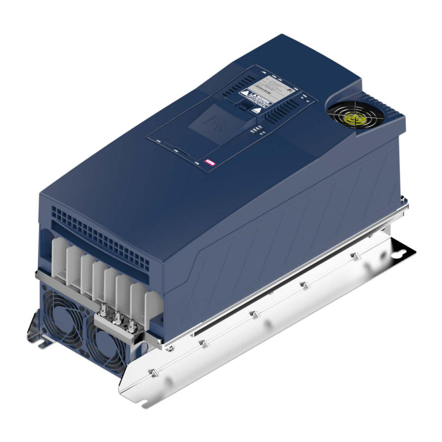
PRODUCT DESCRIPTION 2.3 Product features These instructions for use describes the power unit of the following device: Device type: Drive controller Series: COMBIVERT F6 Power range: 15 kW / 400 V Housing: 2 Peak Power The COMBIVERT F6 is characterized by the following features: •... -
Page 23: Part Code
PRODUCT DESCRIPTION 2.4 Part code x x F 6 x x x - x x x x 1: Air-cooler, mounted version 2: Liquid cooler (water), mounted version 3: Air-cooler, through-mount version IP54-ready Liquid cooler (water), through-mount version IP54- ready 5: Air-cooler, through-mount version IP20 Liquid cooler (water), trough-mount version IP54-ready, sub-mounted braking resistors 7: Liquid cooler (oil), through-mount version IP54-ready... -
Page 24: Table 1: Part Code
PRODUCT DESCRIPTION x x F 6 x x x - x x x x 1: 3ph 230 V AC/DC with braking transistor 2: 3ph 230 V AC/DC without braking transistor 3: 3ph 400 V AC/DC with braking transistor 4: 3ph 400 V AC/DC without braking transistor 3ph 400 V AC/DC incl. GTR7 / max. rectifier / max. -
Page 25: Nameplate
Legend Device series Manufacturer identification Technical data input Technical data output Material number, basic device => code“, KEB internal version number „2.4 Part Configurable options or customer material number/version => „2.5.1 Configurable options“ Barcode Interleaved 2/5 (serial number) Serial-, order number; Year and week of production; Factory... -
Page 26: Configurable Options
PRODUCT DESCRIPTION 2.5.1 Configurable options Features Feature values Description Software Software status of the drive converter SWxxx Axxx Selected accessories Accessories No accessories Limitation to 599 Hz Output frequency activation > 599 Hz activated WSTD Warranty - Standard Warranty Wxxx Warranty extension PSTD Parameterization - Standard... -
Page 27: Technical Data
OPERATING CONDITIONS 3 Technical Data Unless otherwise indicated, all electrical data in the following chapter refer to a 3-phase AC mains. 3.1 Operating conditions 3.1.1 Climatic environmental conditions Storage Standard Class Descriptions Ambient temperature -25…55 °C EN 60721-3-1 Relative humidity EN 60721-3-1 5…95 % (without condensation) Storage height –... -
Page 28: Mechanical Environmental Conditions
OPERATING CONDITIONS 3.1.2 Mechanical environmental conditions Storage Standard Class Descriptions Vibration amplitude 1.5 mm (2…9 Hz) Vibration limits EN 60721-3-1 Acceleration amplitude 5 m/s² (9…200 Hz) Shock limit values 40 m/s²; 22 ms EN 60721-3-1 Transport Standard Class Descriptions Vibration amplitude 3.5 mm (2…9 Hz) Vibration limits Acceleration amplitude 10 m/s²... -
Page 29: Electrical Operating Conditions
OPERATING CONDITIONS 3.1.4 Electrical operating conditions 3.1.4.1 Device classification Requirement Standard Class Descriptions Overvoltage category – EN 61800-5-1 Non-conductive pollution, occasional conden- Pollution degree EN 60664-1 sation when PDS is out of service. Table 5: Device classification 3.1.4.2 Electromagnetic compatibility For devices without an internal filter, an external filter is required to comply with the following limits. -
Page 30: Device Data Of The Peak Power Devices
3.2.1 Overview of the Peak Power devices The technical data are for 2/4-pole standard motors. With other pole numbers the drive controller must be dimensioned onto the rated motor current. Contact KEB for special or medium frequency motors. Device size... -
Page 31: Voltage And Frequencies For 400V Devices
DEVICE DATA OF THE PEAK POWER DEVICES Device size Housing braking option Max. braking current B_max Min. braking resistor value / Ω B_min Braking transistor Max. cycle time: 120 s; Max ED: 50 % Protection function for braking transistor No protection function available Table 7: Overview of the Peak Power device data Rated operation corresponds to U = 400V, rated switching frequency, output frequency = 50 Hz (4-pole standard asynchronous motor). -
Page 32: Input And Output Currents / Overload For Peak Power Devices
DEVICE DATA OF THE PEAK POWER DEVICES 3.2.2.1 Example of the calculation of the possible motor voltage: The motor voltage for dimensioning of the drive is depending on the used components. The motor voltage reduces according to the following table: Component Reduction / % Example... -
Page 33: Overload Characteristic (Ol) For Peak Power Devices
DEVICE DATA OF THE PEAK POWER DEVICES 3.2.3.1 Overload characteristic (OL) for Peak Power devices All drive controllers can be operated at rated switching frequency with an utilization of 150 % for 60s. The OL overload function is a root mean square (RMS) function. The greater the differ- ence between the overload and underload phases, the greater the deviation of the RMS from the arithmetic mean value. -
Page 34: Figure 3: Switch-Off Time T Depending On The Overload I/In At Oc Level 230
DEVICE DATA OF THE PEAK POWER DEVICES Overload characteristic (OC level 230 %) ① ② Motor current / drive controller rated currrent / % Legend Thermal overload limit Limitation by the software current limit (the limit can be set with parameter is35) Figure 3: Switch-off time t depending on the overload I/IN at OC level 230 % •... -
Page 35: Frequency-Dependent Maximum Current (Ol2) For Peak Power Devices
DEVICE DATA OF THE PEAK POWER DEVICES Operation in the range of the thermal overload limit Due to the high steepness of the overload characteristic, the duration of a permissible overload in this range ① cannot be determined exactly. Therefore, the design of the drive controller should be assumed to have a maximum overload time of 300s. -
Page 36: Figure 4: Typical Overload Characteristics In The Lower Output Frequencies (Ol2) Example
DEVICE DATA OF THE PEAK POWER DEVICES The following characteristic curve indicates the permissible maximum current for the out- put frequency values 0 Hz, 3.1 Hz, 6.2 Hz, 12.5 Hz, 25 Hz and 50 Hz. Device size 16 is represented exemplary. Output frequency / Hz Legend Overcurrent I... -
Page 37: Power Dissipation At Rated Operation Of The 400V Devices
DEVICE DATA OF THE PEAK POWER DEVICES The values for the respective device size are listed in the following tables. Frequency-dependent maximum current Device size Rated switching frequency 4 kHz Output frequency / Hz 12,5 2 kHz 127 203 230 230 230 230 Frequency-dependent maximum current @ f / % 4 kHz... -
Page 38: Fuse Protection Of The Drive Controllers Of The Peak Power Devices
DEVICE DATA OF THE PEAK POWER DEVICES 3.2.5 Fuse protection of the drive controllers of the Peak Power devices Max. size of the fuse / A Device = 400 V = 480 V = 480 V size gG (IEC) class „J“ SCCR 30 kA SCCR 5 kA SCCR 30 kA... -
Page 39: General Electrical Data
GENERAL ELECTRICAL DATA 3.3 General electrical data 3.3.1 Switching frequency and temperature The drive controller cooling is designed by way that the heat sink overtemperature threshold is not exceeded at rated conditions. A switching frequency higher than the rat- ed switching frequency also produces higher losses and thus a higher heat sink heating. If the heat sink temperature reaches a critical threshold (T ), the switching frequency can be reduced automatically step by step. -
Page 40: Dc Link / Braking Transistor Function
GENERAL ELECTRICAL DATA 3.3.2 DC link / braking transistor function Destruction of the drive controller if the value falls below the NOTICE minimum brake resistance value ► The minimum brake resistance value must not fall below! DC link Inverter Motor Rectifier Braking transistor... -
Page 41: Fan
GENERAL ELECTRICAL DATA 3.3.3 Fan Device size Number Interior fan Speed-variable Number Heat sink fan Speed-variable Table 19: The fans are not speed-variable. NOTICE Destruction of the fan! ► Take care that no foreign substances drop into the fan! -
Page 42: Switching Behaviour Of The Fans
GENERAL ELECTRICAL DATA 3.3.3.1 Switching behaviour of the fans The fans have different switch-on and switch-off points. The switching point for the switch-on temperature ① is adjustable. The hysteresis for the switch-off temperature ② cannot be changed. The switching behaviour of the fans depends on the heat sink and interior temperature. -
Page 43: Installation
DIMENSIONS AND WEIGHTS 4 Installation 4.1 Dimensions and weights 4.1.1 built-in version air cooler für M6 for M6 für M6 for M6 Housing Weight 5 kg Dimensions All dimensions in mm Figure 7: Dimensions built-in version air cooler... -
Page 44: Push-Through Version Air Cooler Ip20-Ready
DIMENSIONS AND WEIGHTS 4.1.2 Push-through version air cooler IP20-ready 24,5 Housing Weight 5.2 kg Dimensions All dimensions in mm Figure 8: Dimensions push-through version air cooler IP20-ready Optional push-through frame for the IP20-ready push-through version: 00F6V80-2004. Further information => „5.3.3 Mounting kit push-through frame for IP20-ready devices“. -
Page 45: Push-Through Version Air-Cooling Ip54-Ready
DIMENSIONS AND WEIGHTS 4.1.3 Push-through version air-cooling IP54-ready 245,3 für M5 (8x) 79,1 for M5 (8x) Ausschnitt cut-out Housing Weight 5.2 kg Dimensions All dimensions in mm Figure 9: Dimensions push-through version air cooler IP54-ready... -
Page 46: Control Cabinet Installation
CONTROL CAbINET INSTALLATION 4.2 Control cabinet installation 4.2.1 Mounting instructions For the mounting of the drive controllers the following mounting materials with the appro- priate quality were tested by KEB. Required material Tightening torque 6,5 Nm Socket screw ISO 4762 - M6 - 8.8 58 lb inch ―... -
Page 47: Mounting Distances
CONTROL CAbINET INSTALLATION 4.2.2 Mounting distances Power dissipation for the control cabinet dimension => „3.2.4 Power dissipation at rated operation of the 400V devices“. A lower value can be used here depending on the op- erating mode/load. Mounting the drive controller For reliable operation, the drive controller must be mounted without any dis- tance on a smooth, closed, metallically bright mounting plate. -
Page 48: Installation Of Ip54-Ready Devices
② ③ ④ Legend IP20 zone IP54 zone KEB COMBIVERT Housing (e.g. control cabinet wall) Housing (e.g. Control cabinet rear) Figure 11: Installation of IP54-ready devices IP54 zone: Heat sink outside the housing The protection class IP54 can only be achieved when the device is properly installed. -
Page 49: Control Cabinet Ventilation
CONTROL CAbINET INSTALLATION 4.2.4 Control cabinet ventilation If construction-conditioned the control cabinet cannot be without indoor ventilation, ap- propriate filters must avoid suction of foreign objects. Front and side view of the coolant inlet Direction of the airflow Coolant outlet Coolant inlet Figure 12: Control cabinet ventilation... -
Page 50: Airflow Of The Drive Converter
CONTROL CAbINET INSTALLATION 4.2.5 Airflow of the drive converter ① ② ③ ⑥ ④ ⑤ Legend Airflow direction Interior fan (from housing 4) Drive converter (power unnit and control) Drive converter (heat sink) Interior fan for (housing 2 and 3) Heatsink fan Housing (e.g. -
Page 51: Installation And Connection
OVERVIEW OF THE COMbIVERT F6 5 Installation and Connection 5.1 Overview of the COMbIVERT F6 Housing 2 Name Description Fixing points for the optional shielding plates. The shielding e.g. from the motor cable is laid on the mounting plate in the control cabinet or on the shield connection braket (optionally available). -
Page 52: Figure 15: F6 Housing 2 Front View
OVERVIEW OF THE COMbIVERT F6 Housing 2 Name Description Power circuit terminals for: • Mains input • Braking resistor • DC supply • Motor connection Protective earth; when connecting the protective earth, each terminal may be assigned only once. Fixing points for the optional shielding plates. -
Page 53: Figure 16: F6 Housing 2 Rear View With Control Board Application
Figure 16: F6 housing 2 Rear view with control board APPLICATION Further information can be found in the respective control board manual. Instructions for use COMBIVERT F6 control board APPLICATION https://www.keb.de/fileadmin/media/Manuals/dr/ma_dr_f6-cu-a-inst-20118593_ en.pdf Instructions for use COMBIVERT F6 control board COMPACT https://www.keb.de/fileadmin/media/Manuals/dr/ma_dr_f6-cu-k-inst-20144795_ en.pdf... -
Page 54: Connection Of The Power Unit
CONNECTION OF THE POWER UNIT 5.2 Connection of the power unit NOTICE Destruction of the drive controller! ► Never exchange mains input and motor output! 5.2.1 Connection of the voltage supply The COMBIVERT F6 housing 2 can be supplied from the mains. The starting current limiting is arranged before the DC link. -
Page 55: Terminal Block X1A
CONNECTION OF THE POWER UNIT 5.2.1.1 Terminal block X1A Max. number Cross-section for terminal connec- Tightening Name Function of conduc- tion torque tors Mains connection 3-phase Flexible cable with wire-end ferrule DC terminals with plastic collars 2.5...10 mm² For IEC: 2 1.5 Nm For 2 conductors 0.5mm...1.5mm²... -
Page 56: Protective Earth And Functional Earth
The use of the functional earth (FE) is not required if the frequency inverter is EMC-technically wired. The functional earth may not be wired green / yellow! Notes on EMC-compatible installation can be found here. www.keb.de/fileadmin/media/Manuals/emv/0000neb0000.pdf... -
Page 57: Ac Mains Connection
CONNECTION OF THE POWER UNIT 5.2.3 AC mains connection 5.2.3.1 AC supply 3-phase ① ② ③ ④ ⑤ ⑥ Description Mains phase 3-phase TN, TT The rated voltage between one phase conductor and earth potential (or the Mains form neutral point in the IT system) must not exceed 300V, USA UL: 480 / 277 V. -
Page 58: Note On Hard Power Systems
CONNECTION OF THE POWER UNIT 5.2.3.3 Note on hard power systems The service life of drive controllers with voltage DC link depends on the DC voltage, am- bient temperature and the current load of the electrolytic capacitors in the DC link. The use of mains chokes can increase the service life of the condensators to a considerable extent, especially when connecting to "hard“... -
Page 59: Dc Connection
CONNECTION OF THE POWER UNIT 5.2.4 DC connection NOTICE DC operation ► DC operation is only permitted after consultation with KEB! 5.2.4.1 Terminal block X1A DC connection Max. number Cross-section for terminal connec- Tightening Name Function of conduc- tion torque... -
Page 60: Connection Of The Motor
➂ ➃ Control P A/K Legend KEB COMBIVERT Apply motor cable, shielding on both sides over a large surface on the bare metallic frame or mounting plate (remove paint if necessary) Three-phase motor Temperature monitoring (optional) => Instructions for use "Control unit“... -
Page 61: Terminal Block X1A Motor Connection
CONNECTION OF THE POWER UNIT 5.2.5.2 Terminal block X1A motor connection Max. number Cross-section for terminal connec- Tightening Name Function of conduc- tion torque tors Flexible cable with wire-end ferrule with plastic collars 2.5...10 mm² For IEC: 2 1.5 Nm For 2 conductors 0.5mm...1.5mm²... -
Page 62: Selection Of The Motor Line
The maximum motor cable length is depending on the capacity of the motor cable as well as on the EMC emitted interference. External measures must be taken here (e.g. the use of a line filter). The following information is valid for the operation under rated conditions and the use of KEB filters listed under chapter => „5.3.1 Filters and chokes“. Max. motor cable length shielded in accordance with EN 61800-3... -
Page 63: Motor Cable Length For Parallel Operation Of Motors
CONNECTION OF THE POWER UNIT 5.2.5.5 Motor cable length for parallel operation of motors The resulting motor cable length for parallel operation of motors, or parallel installation with multiple cables arises from the following formula: √ resulting motor cable length = ∑single cable lengths x Number of motor cables 5.2.5.6 Motor cable cross-section The motor cable cross-section is dependent •... -
Page 64: Connection Of The Temperature Monitoring And Brake Control (X1C)
CONNECTION OF THE POWER UNIT 5.2.5.8 Connection of the temperature monitoring and brake control (X1C) A switchable temperature evaluation is implemented in the COMBIVERT. There are different types for the evaluation available. These are dependending on the control board => instruction manual „control board“. The desired operating mode can be adjusted via software (dr33). If the evaluation is not required, it must be deactivated via software (parameter pn33 = 7) =>... -
Page 65: Figure 27: Connection Of The Brake Control
CONNECTION OF THE POWER UNIT For control board APPLICATION and COMPACT. The voltage to the control of a brake is decoupled from the ➀ ➃ internal voltage supply. The brake works only with external voltage supply. = 24V For control board PRO = 2A _max The brake can be supplied with both, internal and external... -
Page 66: Connection And Use Of A Braking Resistor
CONNECTION OF THE POWER UNIT 5.2.6 Connection and use of a braking resistor CAUTION Fire risk by using brake resistors ! ► The risk of fire can be significantly reduced by using „intrinsically safe braking resistors“ or by using suitable monitoring functions / circuits. Destruction of the frequency inverter if the vale has fallen below NOTICE the minimum brake resistance value! ►... -
Page 67: Terminal Block X1A Connection Braking Resistor
CONNECTION OF THE POWER UNIT 5.2.6.1 Terminal block X1A connection braking resistor Max. number Cross-section for terminal connec- Tightening Name Function of conduc- tion torque tors Flexible cable with wire-end ferrule with plastic collars 2.5...10 mm² For IEC: 2 Connection for 1.5 Nm For 2 conductors 0.5mm...1.5mm²... -
Page 68: Use Of Intrinsically Safe Braking Resistors
Wiring of an intrinsically safe braking resistor Intrinsically safe braking resisitors behave in error case such as a safety fuse. They interrupt themselves without fire risk. More information about intrinsically safe braking resistors www.keb.de/fileadmin/media/Manuals/dr/ma_dr_safe-braking- resis- tors-20106652_en.pdf 5.2.6.3 Use of non-intrinsically safe braking resistors WARNING... -
Page 69: Accessories
ACCESSORIES 5.3 Accessories 5.3.1 Filters and chokes Voltage class Drive controller size HF filter Mains choke 50 Hz / 4 % U 400 V 16E6T60-3000 16Z1B04-1000 Table 24: Filters and chokes for Peak Power devices The specified filters and chokes are designed for rated operation. 5.3.2 Mounting kit shield connection brakets Name Material number Mounting kit shield connection braket control unit... -
Page 70: Side-Mounted Braking Resistors
ACCESSORIES 5.3.5 Side-mounted braking resistors Technical data and design about intrinsically safe braking resistors => https://www.keb.de/fileadmin/media/Manuals/dr/ma_dr_ safe-braking-resistors-20106652_en.pdf Technical data and design about non-intrinsically safe braking resistors => https://www.keb.de/fileadmin/media/Manuals/ dr/ma_dr_braking-resistors-20116737_en.pdf... -
Page 71: Certification
CERTIFICATION 6 Certification 6.1 CE-Marking CE marked drive controllers were developed and manufactured to comply with the reg- ulations of the Low-Voltage Directive and EMC directive. The harmonized standards of the series EN 61800-5-1 EN 61800-3 were used. For further information regarding the CE declarations of conformity =>... -
Page 72: Ul Certification
CERTIFICATION 6.2 UL certification Acceptance according to UL is marked at KEB drive controllers with the adjacent logo on the nameplate. To be conform according to UL for use on the North American and Canadian Market the following additionally instructions must be observed (original text of the UL-File): •... -
Page 73: Further Informations And Documentation
CERTIFICATION 6.3 Further informations and documentation You find supplementary manuals and instructions for the download under www.keb.de/de/service/downloads General instructions • EMC and safety instructions • Manuals for additional control boards, safety modules, fieldbus modules, etc. Instruction and information for construction and development • Input fuses in accordance with UL • Programming manual for control and power unit •... -
Page 74: Revision History
REVISION HISTORy 7 Revision History Version Date Description 2022-11 Series version of the instructions for use... - Page 75 / Mitjer, Nave 8 - Pol. Ind. LA MASIA E-Mail: info@keb.cz Internet: www.keb.cz 08798 Sant Cugat Sesgarrigues (Barcelona) Spain Tel: +34 93 8970268 Fax: +34 93 8992035 E-Mail: vb.espana@keb.de Société Française KEB SASU France Z.I. de la Croix St. Nicolas 14, rue Gustave Eiffel...
- Page 76 Automation with Drive www.keb.de KEB Automation KG Suedstrasse 38 32683 Barntrup Tel. +49 5263 401-0 E-Mail: info@keb.de...
Need help?
Do you have a question about the COMBIVERT F6 Series and is the answer not in the manual?
Questions and answers