Sign In
Upload
Manuals
Brands
Hughes Manuals
Network Router
HN9500
Hughes HN9500 Manuals
Manuals and User Guides for Hughes HN9500. We have
2
Hughes HN9500 manuals available for free PDF download: Installation Manual, User Manual
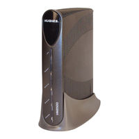
Hughes HN9500 Installation Manual (136 pages)
Satellite Router
Brand:
Hughes
| Category:
Network Router
| Size: 8.82 MB
Table of Contents
Table of Contents
3
Understanding Safety Alert Messages
11
Messages Concerning Personal Injury
11
Messages Concerning Property Damage
11
Safety Symbols
11
Scope and Audience
13
Chapter 1: Satellite Router Overview
15
Figure 1: HN9500 Satellite Router
15
Supported Configurations
16
Figure 2: Single-Host Configuration
16
Figure 3: Multiple-Host Configuration in an Ethernet Wired LAN
17
Figure 4: Multiple-Host Configuration in a Wireless LAN
17
Figure 5: Private Network Configuration
17
Satellite Router Specifications
18
Table 1: Specifications for the HN9500 Satellite Router
18
Chapter 2: Preparing for Installation
21
Installation Summary
22
Figure 6: Satellite Router Installation Summary
23
Installation Checklist
24
Table 2: Related Installation Documents
24
Conducting a Site Survey
25
Instructions for Other Terminal Components
25
Power Supply Information
26
Figure 7: Power Supply for the HN9500 Satellite Router
26
Table 3: Power Supply Specifications for the HN9500 Satellite Router
26
Primary Tools and Equipment Needed for Installation
27
Additional Equipment
27
Use a Surge Protector
28
Requirements for IFL Cables, Connectors, and Ground Blocks
28
A Hub May be Required
28
Computer Requirements
28
Chapter 3: Installing the Satellite Router
29
Operating Environment
30
Ventilation and Heat Sources
30
Router Operating Position
30
Attaching or Removing the Pedestal Base
30
Attaching the Base
30
Removing the Base
31
Powering up the Router
31
Figure 8: Attaching or Removing the HN9500 Pedestal Base
31
Connecting the Installer Laptop to the Router
32
Figure 9: Powering up the Router
32
Figure 10: Connecting the Installer's Laptop Computer to the Router
32
Entering the Installation Parameters
33
Figure 11: System Control Center Home Page
34
Figure 12: Icon for Opening Advanced Pages
34
Figure 13: Installation Parameters Screen
35
Figure 14: Fields Where Latitude and Longitude Are Entered
36
Figure 15: Example of a GPS Receiver Display
37
Table 4: Converting GPS Display Formats
37
Figure 16: State Code Displayed below Latitude and Longitude Fields
38
Figure 17: Terminal Pointing Info Screen
38
Chapter 4: Installing Outdoor Equipment and Antenna Pointing
41
Installing the IFL Cables
42
Routing and Connecting the IFL Cables
42
IFL Grounding Requirement
42
Figure 18: In-Line Connection of the DAPT
42
Labeling the IFL Cables
43
Connecting the IFL Cables to the Router
43
Figure 19: Connecting the Transmit and Receive Cables
43
Pointing the Antenna
44
Chapter 5: Commissioning the Satellite Router
45
Prerequisites for Commissioning
46
Monitoring the Commissioning Process
46
Figure 20: Terminal Initialization Sequence in Progress
46
Figure 21: Terminal Initialization Sequence Complete
47
Commissioning and Installation Reference Information
48
Commissioning Activities and Progress Messages
49
Table 5: Commissioning Progress Messages
49
Registration Error Messages
50
Table 6: Reasons for Registration Errors and Corrective Actions
50
Terminal Info Parameters
51
Table 7: Parameters in Terminal Info Section (Appears on Two Installation Screens)
51
Troubleshooting Installation Problems
53
Table 8: Guidelines for Installation Troubleshooting
53
Chapter 6: Validating the Installation
55
A Quick Look at the Validation Procedure
56
Prerequisites
56
Figure 22: Latest Values Compared to Target Values (Partial Screen)
56
Accessing the OVT
57
Figure 23: Validate Link on System Control Center Page
58
Figure 24: Installation Portal, Installer Login Screen
59
Figure 25: Installation Portal Welcome Screen
60
Figure 26: Data Collection Screen
60
Figure 27: Site and Installer ID Information
61
Figure 28: OVT Screen Comparing Latest and Target Values
61
Chapter 7: Activating the Hughesnet Service
63
Service Activation Prerequisites
64
Connecting the Satellite Router to the Customer's Computer
64
Figure 29: Terminal Initialization Sequence Screen - Top Part
64
Figure 30: Activate Link Indicating Router Is Ready for Service Activation
65
Figure 31: Connecting Ethernet Cable to Customer's Computer or Other Device
65
Activation Procedure
66
Figure 32: Activate Link on the System Control Center Home Page
67
Figure 33: SAN and PIN Entry Page
68
Figure 34: Welcome Screen
68
Figure 35: Welcome Screen with Service Activated Message
69
Chapter 8: VADB Feature Setup and Testing
71
Prerequisites for VADB Setup and Operation
72
Setting up VADB
72
Verifying VADB Configuration
72
Testing the Router's VADB Components
73
Figure 36: Verifying the VADB Configuration
73
Testing the Phone Line
74
Connecting the Satellite Router to the Telephone Line
74
Figure 37: Select Loopback Test Menu
74
Figure 38: Phone Connection to Support VADB
74
Verifying VADB Functionality
75
Figure 39: VADB Manual Start Command Results (Partial) Screen
76
VADB Troubleshooting
77
Chapter 9: System Control Center
79
Accessing the System Control Center
80
System Control Center Home Page
80
Text Links
81
Figure 40: System Control Center Home Page
81
Common Features on System Control Center Screens
82
Figure 41: Common Features on System Control Center Screens
82
Button Links
83
System Status Button
83
Figure 42: System Control Center Button Links
83
Table 9: Button Links on System Control Center Screens
83
Table 10: System Status Button Colors
83
Ipsec Icon
84
Figure 43: Ipsec Icon
84
Links in the Left Panel
85
Small Icon on System Control Center Screens-Access Advanced Pages
85
Status and Information Screens
85
Figure 44: Icon for Accessing the Advanced Pages
85
Figure 45: Format of Status and Information Screens
86
Figure 46: Example of a State Code
86
State Codes on Status and Information Screens
86
Red Flag Indicator
87
System Status Page
87
Figure 47: Red Flag Problem Indicator
87
Figure 48: System Status Page
87
Table 11: System Status Parameters - Typical Values and Range
88
Typical Values for System Status Parameters
88
Red Flags on System Status Page
90
Table 12: Red Flags on System Status Page
90
Reception Information Page
91
Figure 49: Reception Information Page
91
Table 13: Reception Information Parameters - Typical Values and Range
92
Typical Values for Reception Information Parameters
92
Red Flags on Reception Information Page
93
Table 14: Red Flags on Reception Information Page
93
Transmission Information Page
94
Figure 50: Transmission Information Page
94
Red Flags on Transmission Information Page
95
Typical Values for Transmission Information Parameters
95
Terminal Status Page
95
Table 15: Transmission Information Parameters - Typical Values and Range
95
Figure 51: Terminal Status Page (Top Part)
96
Table 16: Terminal Status Parameters - Typical Values and Range
97
Typical Values for Terminal Status Parameters
97
System Information Page
98
Typical Values for System Information Parameters
98
Figure 52: System Information Page (Top Part)
98
Table 17: System Information Parameters - Typical Values and Range
99
State Codes
101
Figure 53: Examples of State Codes
102
Table 18: State Codes
102
Viewing the State Codes List
105
Connectivity Test Page
106
Figure 54: Terminal Connectivity Test Page
106
Chapter 10: Leds
107
Front Panel Leds
108
Figure 55: Front Panel Leds on the HN9500 Router
108
Table 19: Front Panel LED Indications
108
LAN Port Leds
109
Figure 56: LAN Port Leds
109
Chapter 11 Troubleshooting
111
Rescue Switch
112
Troubleshooting Common Problems
112
Figure 57: Problem Troubleshooting Page
112
Cannot Access the System Control Center
113
Testing Connectivity to the Satellite
113
Figure 58: Satellite Loopback Connectivity Test
113
Figure 59: Terminal Connectivity Test Page
114
Figure 60: Connectivity Test Results Page
114
VADB - Router Cannot Connect
115
VADB - VADB Connection State down
115
VADB - Router Remains in VADB Mode
116
Chapter 12: Advanced
117
Accessing the Advanced Pages
118
Figure 61: Icon for Accessing Advanced Pages
118
Figure 62: Advanced Pages Example Showing the Advanced Menu
118
Expanding and Collapsing Menus
119
Opening the Installation Sub-Menu
119
Appendix A: Alternate Address for Installing the Router
121
Configuring the Installer Laptop IP Address
121
Configuring a Link-Local IP Address on the Installer Laptop
122
Configuring a Second IP Address on the Installer Laptop
123
Figure 63: Internet Protocol Properties Dialog
123
Using the Alternate Installation Address
124
Figure 64: Settings for Link-Local and Second Address on the Laptop
124
Appendix B: Standards Compliance
125
Telecommunications Standards
125
FCC Part 68
125
Table 20: HN9500 Standards Compliance
125
Ringer Equivalence Number (REN)
126
Discontinuation of Service
126
Telephone Company Changes
126
Repairs in the United States
126
Industry Canada Certification
127
Electromagnetic Interference (EMI)
127
FCC Part 15
127
Canada Class B Warning
128
Operational and Safety Requirements for Canada
128
Repairs in Canada
128
Appendix C: Acronyms Used in this Guide
129
Advertisement
Hughes HN9500 User Manual (94 pages)
Satellite Router
Brand:
Hughes
| Category:
Network Router
| Size: 4.62 MB
Table of Contents
Table of Contents
3
Messages Concerning Personal Injury
11
Messages Concerning Property Damage
11
Safety Symbols
11
Understanding Safety Alert Messages
11
Contact Information
13
Chapter 1: Satellite Router Overview
15
Figure 1: HN9500 Satellite Router
15
Scope of this User Guide
17
Supported Configurations
17
Figure 2: Single-Host Configuration
17
Figure 3: Multiple-Host Configuration in an Ethernet Wired LAN
18
Figure 4: Multiple-Host Configuration in a Wireless LAN
18
Figure 5: Private Network Configuration
18
Satellite Router Specifications
19
Table 1: Specifications for the HN9500 Satellite Router
19
Power Supply Information
20
Figure 6: Power Supply for the HN9500 Satellite Router
20
Table 2: Power Supply Specifications for the HN9500 Satellite Router
20
Operating Environment
21
Ventilation and Heat Sources
21
Router Operating Position
21
Attaching or Removing the Pedestal Base
21
Attaching the Base
21
Removing the Base
22
Computer Requirements
22
Figure 7: Attaching or Removing the HN9500 Pedestal Base
22
Chapter 2: System Control Center
25
Accessing the System Control Center
26
System Control Center Home Page
26
Text Links
27
Figure 8: System Control Center Home Page
27
Common Features on System Control Center Screens
28
Button Links
29
Figure 9: Common Features on System Control Center Screens
29
Figure 10: System Control Center Button Links
29
Table 3: Button Links on System Control Center Screens
29
System Status Button
30
Table 4: System Status Button Colors
30
Ipsec Icon
31
Links in the Left Panel
31
Figure 11: Ipsec Icon
31
Small Icon on System Control Center Screens
32
Status and Information Screens
32
Figure 12: Small Icon on System Control Center Screens
32
State Codes on Status and Information Screens
33
Red Flag Indicator
33
Figure 13: Format of Status and Information Screens
33
Figure 14: Example of a State Code
33
System Status Page
34
Figure 15: Red Flag Problem Indicator
34
Figure 16: System Status Page
34
Typical Values for System Status Parameters
35
Table 5: System Status Parameters - Typical Values and Range
35
Red Flags on System Status Page
37
Table 6: Red Flags on System Status Page
37
Reception Information Page
38
Figure 17: Reception Information Page
38
Typical Values for Reception Information Parameters
39
Table 7: Reception Information Parameters - Typical Values and Range
39
Red Flags on Reception Information Page
40
Table 8: Red Flags on Reception Information Page
40
Transmission Information Page
41
Figure 18: Transmission Information Page
41
Typical Values for Transmission Information Parameters
42
Table 9: Transmission Information Parameters - Typical Values and Range
42
Red Flags on Transmission Information Page
43
Terminal Status Page
43
Figure 19: Terminal Status Page (Top Part)
43
Typical Values for Terminal Status Parameters
44
Table 10: Terminal Status Parameters - Typical Values and Range
44
System Information Page
45
Figure 20: System Information Page (Top Part)
45
Typical Values for System Information Parameters
46
Table 11: System Information Parameters - Typical Values and Range
46
State Codes
49
Figure 21: Examples of State Codes
49
Table 12: State Codes
49
Viewing the State Codes List
52
Checking Download Allowance Status
53
Figure 22: Download Allowance Status Screen
53
Connectivity Test Page
54
Figure 23: Download Allowance Exceeded - Speed Limited
54
Figure 24: Terminal Connectivity Test Page
54
Chapter 3: Leds
55
Front Panel Leds
56
Figure 25: Front Panel Leds on the HN9500 Router
56
Table 13: Front Panel LED Indications
56
LAN Port Leds
57
Figure 26: LAN Port Leds
57
Chapter 4: VADB Feature Description
59
VADB Phone Line Connection
60
Figure 27: VADB Phone Line Connection
60
Chapter 5: Troubleshooting
61
Troubleshooting Common Problems
62
Cannot Access the System Control Center
62
Figure 28: Problem Troubleshooting Page
62
Testing Connectivity to the Satellite
63
Figure 29: Satellite Loopback Connectivity Test
63
Figure 30: Terminal Connectivity Test Page
64
Figure 31: Connectivity Test Results Page
64
Hot Cable Connector
65
VADB - Router Remains in VADB Mode
65
Appendix A: Computer Settings
67
Understanding the Router Address and Computer Address
67
Figure 32: Example of Addressing Parameters Showing Available Private IP Addresses
67
Configuring a Computer to Use DHCP
68
Figure 33: Example of Addressing Parameters Showing One Available Static IP Address
68
Configuring Windows 7 to Use DHCP
69
Figure 34: Network and Sharing Center - Windows 7
69
Figure 35: Local Area Connection Properties - Windows 7
70
Figure 36: Internet Protocol Properties - Windows 7
70
Configuring Windows Vista to Use DHCP
71
Figure 37: Network Connections - Windows Vista
71
Figure 38: Local Area Connection Properties - Windows Vista
71
Configuring Windows XP to Use DHCP
72
Figure 39: Internet Protocol Properties - Windows Vista
72
Figure 40: Network Connections - Windows XP
73
Figure 41: Local Area Connection Properties - Windows XP
73
Configuring Windows 2000 to Use DHCP
74
Figure 42: Internet Protocol Properties - Windows XP
74
Figure 43: Local Area Connection Properties Dialog - Windows 2000
75
Figure 44: Internet Protocol Properties - Windows 2000
75
Configuring a Mac Computer to Use DHCP
76
Figure 45: Mac Network Screen
76
Figure 46: Select DHCP from the Configure Drop-Down Menu
76
Configuring a Computer for a Static IP Address
77
Configuring Windows 7 to Use a Static IP Address
77
Figure 47: Network and Sharing Center - Windows 7
77
Figure 48: Local Area Connection Properties - Windows 7
78
Figure 49: Internet Protocol Properties - Windows 7
78
Configuring Windows Vista to Use a Static IP Address
79
Figure 50: Network Connections - Windows Vista
79
Figure 51: Local Area Connection Properties - Windows Vista
79
Configuring Windows XP to Use a Static IP Address
80
Figure 52: Internet Protocol Properties - Windows Vista
80
Figure 53: Accessing Local Area Connection Properties - Windows XP
81
Figure 54: Local Area Connection Properties Dialog - Windows XP
81
Configuring Windows 2000 to Use a Static IP Address
82
Figure 55: Internet Protocol Properties - Windows XP
82
Configuring a Mac Computer to Use a Static IP Address
83
Figure 56: Local Area Connection Properties Dialog - Windows 2000
83
Figure 57: Internet Protocol Properties - Windows 2000
83
Figure 58: Mac Network Screen
84
Figure 59: Select Manually from the Configure Drop-Down Menu
84
Configuring Proxy Settings
85
Configuring Internet Explorer to Not Use a Proxy Server
85
Figure 60: LAN Settings - Internet Explorer
85
Appendix B: Standards Compliance
87
HN9500 Satellite Router User Guide
87
Telecommunications Standards
87
FCC Part 68
87
Table 14: HN9500 Standards Compliance
87
Ringer Equivalence Number (REN)
88
Discontinuation of Service
88
Telephone Company Changes
88
Repairs in the United States
88
Industry Canada Certification
89
Electromagnetic Interference (EMI)
89
FCC Part 15
89
Canada Class B Warning
90
Operational and Safety Requirements for Canada
90
Repairs in Canada
90
Appendix C: Acronyms Used in this Guide
91
Advertisement
Related Products
Hughes HX90
Hughes HX200
Hughes HN9200
Hughes HN9400
Hughes HN9800
Hughes HN9600
Hughes HN9000
Hughes HN7000S
Hughes HNS 9201
Hughes HN Series
Hughes Categories
Modem
Antenna
Marine GPS System
Touch terminals
Receiver
More Hughes Manuals
Login
Sign In
OR
Sign in with Facebook
Sign in with Google
Upload manual
Upload from disk
Upload from URL