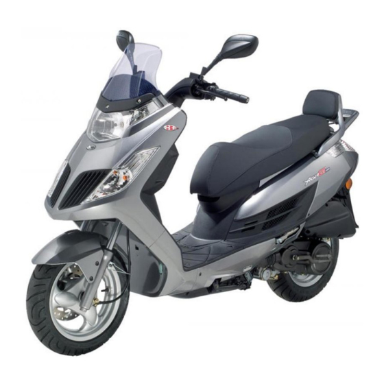
KYMCO DINK 125 Service Manual
Hide thumbs
Also See for DINK 125:
- Service manual (224 pages) ,
- Owner's manual (104 pages) ,
- Specifications (1 page)
Table of Contents
Advertisement
Quick Links
1. GENERAL INFORMATION
1
_________________________________________________________________________________________
_________________________________________________________________________________________
_________________________________________________________________________________________
_________________________________________________________________________________________
_________________________________________________________________________________________
_________________________________________________________________________________________
Serial Number----------------------------------------------------------- 1 - 1
SPECIFICATION (DINK 50)----------------------------------------------- 1 - 2
SPECIFICATION (DINK 125) --------------------------------------------- 1 - 3
Service Precautions ------------------------------------------------- 1 - 4
Torque Values ---------------------------------------------------------- 1 - 8
Special Tools ------------------------------------------------------------ 1-11
Lubrication Points --------------------------------------------------- 1-13
CABLE & HARNESS ROUTING (DINK 125) ---------------------------- 1-15
CABLE & HARNESS ROUTING (DINK 50)------------------------------ 1-30
Troubleshooting------------------------------------------------------ 1-35
GENERAL INFORMATION
DINK 50/125
1
1-0
Advertisement
Table of Contents
Troubleshooting

Related Manuals for KYMCO DINK 125


Summary of Contents for KYMCO DINK 125
- Page 1 SPECIFICATION (DINK 125) --------------------------------------------- 1 - 3 SERVICE PRECAUTIONS ------------------------------------------------- 1 - 4 TORQUE VALUES ---------------------------------------------------------- 1 - 8 SPECIAL TOOLS ------------------------------------------------------------ 1-11 LUBRICATION POINTS --------------------------------------------------- 1-13 CABLE & HARNESS ROUTING (DINK 125) ---------------------------- 1-15 CABLE & HARNESS ROUTING (DINK 50)------------------------------ 1-30 TROUBLESHOOTING------------------------------------------------------ 1-35...
- Page 2 1. GENERAL INFORMATION DINK50/125 SERIAL NUMBER (1) Location of Frame Serial Number DINK 50 DINK 125 Location of Engine Serial Number...
-
Page 3: General Information
1. GENERAL INFORMATION DINK 50/125 Air cleaner type & No Paper element, wet SPECIFICATIONS(DINK 50) 7 L (1.47 lmp gal, Fuel capacity Overall length 2030 mm (81.2 in) 1.82 US gal) Overall width 780 mm (31.2in) Type LFA1 Overall height 1255 mm (50.2 in) Main jet No. - Page 4 1. GENERAL INFORMATION DINK50/125 SPECIFICATIONS (DINK 125) Air cleaner type Paper element, wet Overall length 2030 mm (81.2 in) 11 L (2.31 lmp gal, Overall width 760 mm (30.4 in) Fuel capacity 2.86 US gal) Overall height 1255 mm (50.2 in)
-
Page 5: Service Precautions
1. GENERAL INFORMATION DINK 50/125 SERVICE PRECAUTIONS Apply or add designated greases and lubricants to the specified lubrication Make sure to install new gaskets, O-rings, points. circlips, cotter pins, etc. when reassembling. After reassembly, check all parts for proper tightening and operation. When tightening bolts or nuts, begin with larger-diameter to smaller ones at several times, and tighten to the specified torque... - Page 6 1. GENERAL INFORMATION DINK50/125 If the fuse is burned out, find the cause and The connector shall be inserted repair it. Replace it with a new one completely. according to the specified capacity. If the double connector has a lock, lock it at the correct position.
- Page 7 1. GENERAL INFORMATION DINK 50/125 After clamping, check each wire to make Route harnesses so they are neither sure it is secure. pulled tight nor have excessive slack. Do not pull too tight! Do not squeeze wires against the weld or its clamp.
- Page 8 1. GENERAL INFORMATION DINK50/125 After routing, check that the wire harnesses Symbols: are not twisted or kinked. The following symbols represent the servicing methods and cautions included in this service manual. : Apply engine oil to the Wire harnesses routed along with specified points.
-
Page 9: Torque Values
CYLINDER HEAD: Cylinder head cover 1.2 (12, 8.6) Cylinder head nut (DINK 50) 0.7-1.1(10, 7.2) Apply oil Cylinder head nut (DINK 125) 2 (20, 14) Apply oil Tensioner sealing bolt 0.6 (6, 4) Cam chain tensioner mounting bolt 1.2 (12, 8.6) Cylinder head bolt 1 (10, 7.2) - Page 10 1 (10, 7.2) DRIVE/DRIVEN PULLEY: L crankcase cover 1.2 (12, 8.6) Drive pulley nut (DINK 50) 5.5 (55, 40) Drive pulley nut (DINK 125) 5.5 (55, 40) Clutch outer nut 5.5 (55, 40) Driven pulley assembly plate nut 5.5 (55, 40)
- Page 11 1. GENERAL INFORMATION DINK 50/125 Thread dia. Torque Item Q‘ty Remarks (mm) kgf-m (N-m, lbf-ft) SUSPENSION: Rear shock absorber upper mount bolt 4 (40, 29) Rear shock absorber lower mount bolt 2.7 (27, 19) Rear fork 2.7 (27, 19) BRAKE: Front caliper 2.7 (27, 19) Rear caliper...
- Page 12 1. GENERAL INFORMATION DINK50/125 SPECIAL TOOLS Illustration (Note: the special tools may differ Tool Name Tool No. slightly from those shown in the figure of this manual.) Flywheel puller (Refer to the “STARTER A120E00003 CLUTCH” section in the chapter 10.) Oil seal and bearing A120E00014 installer...
- Page 13 1. GENERAL INFORMATION DINK 50/125 Illustration (Note: the special tools may differ Tool Name Tool No. slightly from those shown in the figure of this manual.) Bearing puller A120E00037 Valve spring compressor (Refer to the “CYLINDER A120E00040 HEAD” section in the chapter 6.) Lock nut wrench (Refer to the “STEERING A120F00002...
- Page 14 1. GENERAL INFORMATION DINK50/125 LUBRICATION POINTS ENGINE Lubrication Points Lubricant •Genuine KYMCO Engine Oil (SAE 10W- Valve guide/valve stem movable part Camshaft protruding surface •API SG Egnine Oil Valve rocker arm friction surface Camshaft drive chain Cylinder lock bolt and nut...
- Page 15 1. GENERAL INFORMATION DINK 50/125 FRAME The following is the lubrication points for the frame. Use general purpose grease for parts not listed. Apply clean engine oil or grease to cables and movable parts not specified. This will avoid abnormal noise and rise the durability of the motorcycle. Engine Oil Throttle Cable Grease...
- Page 16 1. GENERAL INFORMATION DINK50/125 CABLE & HARNESS ROUTING (1) Brake light switch (Front brake) (2) Front brake hose (3) Throttle cable (Note) (4) Left handlebar switch (5) Brake light switch (Rear brake) (6) Rear brake hose (7) Right handlebar switch (A) Pass the front brake hose, rear brake hose, throttle cable, right handlebar switch and left handlebar switch through the guide.
- Page 17 1. GENERAL INFORMATION DINK 50/125 (1) Seat lock cable (2) Rear brake hose (3) Speedometer cable (4) Instrument connectors (5) Fuel fill cap ground wire connector (6) Fuel cap lock cable (7) Radiator bleed hose (8) Flashing relay (9) Coolant fill hose (10) Radiator bleed hose (11) Siphon hose (A) Pass the radiator bleed hose through the guide.
- Page 18 1. GENERAL INFORMATION DINK50/125 (1) Low beam relay (2) Speedometer cable (3) Resistor (4) Fuel tank breather hose (5) Right handlebar switch (6) Left handlebar switch (7) Harness wire (8) Fuel fill hose (9) Throttle cable (10) Seat lock cable (11) Siphon hose (12) Left turn signal light connector (13) Headlight connector...
- Page 19 1. GENERAL INFORMATION DINK 50/125 (1) Throttle cable (2) Harness wire (3) Seat lock cable (4) Speedometer cable (A) Pass the harness wire and throttle cable through the guide. (B) Pass the seat lock cable through the guide pipe. 1-18...
- Page 20 1. GENERAL INFORMATION DINK50/125 (1) Throttle cable (2) Harness wire (3) Seat lock cable (4) Siphon hose (5) Fuel tank breather hose (6) Fuel fill hose (A) Pass the harness wire through the guide. (B) Pass the harness wire and throttle cable through the guide. (C) Pass the seat lock cable through the guide pipe.
- Page 21 1. GENERAL INFORMATION DINK 50/125 (1) Throttle cable (2) AICV air inlet hose (3) Harness wire (4) Seat lock cable (5) Side stand switch wire (A) Pass the seat lock cable through the guide. (B) Pass the seat lock cable and harness wire through the guide. (C) Pass the seat lock cable and harness wire through the guide.
- Page 22 (15) Ground cable (16) Luggage box light connector (17) Side stand switch connector (18) Ignition coil (DINK 125) (19) Carburetor vacuum hose (DINK 125) (20) Ignition coil cable (A) Pass the seat lock cable through the guide. (B) Pass the seat lock cable through the guide.
- Page 23 1. GENERAL INFORMATION DINK 50/125 (1) Heater control connector (2) Auto choke connector (3) Heater connector (4) Fuse box (5) Battery (6) Luggage box light switch (7) Seat lock cable (8) Battery negative cable (9) Harness wire (10) Frame ground terminal (11) Ground cable 1-22...
- Page 24 1. GENERAL INFORMATION DINK50/125 (1) Battery negative terminal (2) Luggage box light connector (3) Battery positive terminal (4) A.C.G/Regulator/Rectifier/Starter relay connectors (5) Light ASSY. RR combination connector (6) Fuse box (7) Harness (A) Pass the harness wire through the plastic band. 1-23...
- Page 25 1. GENERAL INFORMATION DINK 50/125 (1) Rear brake hose (2) Siphon hose (3) Radiator cap (4) Bleed hoses (5) Fan motor switch (6) Upper radiator hose (7) Right turn signal light wire (8) Lower radiator hose (9) Front brake hose (10) Lower radiator pipe (11) Upper radiator pipe (A) Pass the front brake hose through the guide.
- Page 26 1. GENERAL INFORMATION DINK50/125 (1) Fuel hose (between the fuel pump and fuel filter) (2) Fuel hose (between the fuel filter and fuel tank) (3) Lower radiator pipe (4) Upper radiator pipe (5) Bleed hose (6) Rear brake hose (7) Water flow hose (A) Pass the fuel hose and water flow hose through the guide.
- Page 27 1. GENERAL INFORMATION DINK 50/125 (1) Thermostat (2) Bleed hose (connect the thermostat) (3) Fuel hose (4) Water flow hose (5) Water hose (between the water pump and cylinder) (6) Upper radiator hose (connect the thermostat) (7) Lower radiator hose (8) Rear brake hose (A) Pass the rear brake hose through the guide.
- Page 28 1. GENERAL INFORMATION DINK50/125 (1) Light ASSY. RR combination connector (2) Battery positive cable (3) Starter relay (4) Regulator/Rectifier (5) Ground cable (6) CDI (7) A.C.G. wire (8) Upper radiator hose (9) Lower radiator hose (10) Rear brake hose (11) Starter motor cable (12) Engine ground terminal (connect the starter motor) (13) A.C.G/Regulator/Rectifier/Starter relay connectors (14) Harness wire...
- Page 29 (14) DINK 125: Fuel hose (between fuel pump and carburetor) (A) Pass the auto choke wire (DINK 125), throttle cable and harness wire through the guide. (B) Pass the fuse hose and vacuum hose (DINK 125) through the plastic band.
- Page 30 1. GENERAL INFORMATION DINK50/125 (1) AICV vacuum hose (2) Air inlet hose (3) AICV control solenoid valve (4) Air supply hose (5) Air inlet pipe (6) Reed valve cover (A) Pass the AICV vacuum hose through the guide. 1-29...
- Page 31 1. GENERAL INFORMATION DINK 50/125 DINK 50 CABLE & HARNESS ROUTING ( Rear Brake Switch Front Brake Switch Rear Brake Cable Throttle Cable Front Brake Cable Speedometer Cable Resistor Ignition Switch Regulator/Rectifier Connector Horn 1-30...
- Page 32 1. GENERAL INFORMATION DINK50/125 Throttle Cable CDI Unit Breather Tube Ignition Coil Ignition Coil Wire Secondary Air Tube Harness Wire Vacuum Tube 1-31...
- Page 33 1. GENERAL INFORMATION DINK 50/125 Starter Relay Fuse Box Fuel Tube Fuel Vacuum Tube 1-32...
- Page 34 1. GENERAL INFORMATION DINK50/125 Ignition Switch Fuel Hose Harness Wire Fuel Tube Fuel Unit Wire Speedometer Cable Front Brake Cable 1-33...
- Page 35 1. GENERAL INFORMATION DINK 50/125 Secondary Air Vacuum Tube Fuel Out Tube Ignition Coil Wire A.C.G Tube Choke Tube Fuel Unit Tube Fuel Tank Fuel Strainer Fuel Pump Vacuum Tube 1-34...
-
Page 36: Troubleshooting
1. GENERAL INFORMATION DINK50/125 TROUBLESHOOTING ENGINE WILL NOT START OR IS HARD TO START Inspection/Adjustment Probable Cause Symptom Check if fuel reaches carburetor by loosening drain screw Empty fuel tank Clogged carburetor fuel inlet tube, vacuum tube or fuel tube Clogged auto fuel valve Fuel reaches Fuel does not... - Page 37 1. GENERAL INFORMATION DINK 50/125 ENGINE LACKS POWER Inspection/Adjustment Probable Cause Symptom Start engine and Clogged air cleaner accelerate lightly for Restricted fuel flow observation Clogged fuel line between fuel tank and carburetor Engine speed does Engine speed Clogged exhaust muffler increases not increase Faulty auto bystarter...
- Page 38 1. GENERAL INFORMATION DINK50/125 POOR PERFORMANCE (ESPECIALLY AT IDLE AND LOW SPEEDS) Inspection/Adjustment Symptom Probable Cause Check ignition timing Faulty ignition unit Incorrect timing Correct timing Faulty A.C. generator Check carburetor pilot screw adjustment Mixture too rich (turn screw out) Correctly adjusted Incorrectly adjusted Mixture too lean (turn screw in)
- Page 39 1. GENERAL INFORMATION DINK 50/125 POOR PERFORMANCE (AT HIGH SPEED) Inspection/Adjustment Symptom Probable Cause Check ignition timing Faulty ignition unit Correct timing Incorrect timing Faulty A.C. generator Check valve clearance Improperly adjusted valve Correctly adjusted Incorrectly adjusted clearance Worn valve seat Check fuel pump for fuel supply Empty fuel tank...
- Page 40 1. GENERAL INFORMATION DINK50/125 ENGINE NOISE Symptom Probable Cause Valve clearance too large Valve noise Worn camshaft lobe Worn piston rings Worn piston pin and connecting rod small end Piston noise Excessive carbon build-up in combustion chamber Damaged cam chain tensioner Worn cam gear teeth Cam chain noise Worn or damaged cam chain...
- Page 41 1. GENERAL INFORMATION DINK 50/125 CLUTCH, DRIVE AND DRIVEN PULLEYS Symptom Probable Cause Worn or slipping drive belt Broken ramp plate Broken drive face spring Engine starts but motor- Separated clutch lining cycle does not move Damaged driven pulley shaft splines Damaged final gear Seized final gear Broken shoe spring...
- Page 42 1. GENERAL INFORMATION DINK50/125 STARTER MOTOR 1. Starter motor won‘t turn Symptom Inspection/Adjustment Probable Cause Check operation of brake light switch by Burned out fuse applying brake Weak or dead battery Stoplight does not Stoplight comes on Faulty stop switch come on Loose or disconnected connectors Check battery circuit...
- Page 43 1. GENERAL INFORMATION DINK 50/125 NO SPARK AT SPARK PLUG Inspection/Adjustment Symptom Probable Cause Replace with a new spark plug and inspect again Good spark Weak or no spark Faulty spark plug Check spark plug cap and high-tension wire for looseness Not loose Loose Faulty spark plug...
- Page 44 1. GENERAL INFORMATION DINK50/125 POOR CHARGING (BATTERY OVER DISCHARGING OR OVERCHARGING) Undercharging Inspection/Adjustment Symptom Probable Cause Start engine and test limit voltage of battery terminals Faulty AC generator Voltage does not Normal voltage Faulty regulator/rectifier increase Faulty battery Measure resistance between AC generator coil terminals Shorted AC generator coil...
- Page 45 1. GENERAL INFORMATION DINK 50/125 FUEL GAUGE 1. Pointer does not register correctly (Ignition switch ON) Inspection/Adjustment Symptom Probable Cause Check battery circuit by operating turn signals Burned out fuse Weak or dead battery Signals operate Signals dim, remain Faulty ignition switch properly on or don‘t operate Loose or disconnected...
- Page 46 1. GENERAL INFORMATION DINK50/125 gauge STEERING HANDLEBAR DOES NOT TRACK STRAIGHT Symptom Probable Cause (Front and rear tire pressures are normal) Steering stem nut too tight Steering is heavy Broken steering steel balls Excessive wheel bearing play Front or rear wheel is Bent rim wobbling Loose axle nut...
- Page 47 . EXHAUST MUFFLER/FRAME COVERS DINK50/125 __________________________________________________________________________________ __________________________________________________________________________________ __________________________________________________________________________________ __________________________________________________________________________________ __________________________________________________________________________________ EXHAUST MUFFLER/FRAME COVERS __________________________________________________________________________________ SCHEMATIC DRAWING ------------------------------------------------- 2- 1 SERVICE INFORMATION------------------------------------------------ 2- 2 TROUBLESHOOTING----------------------------------------------------- 2- 2 FASTENER REMOVAL AND REINSTALLATION------------------ 2- 3 FRAME COVERS REMOVAL/INSTALLATION --------------------- 2- 4 EXHAUST MUFFLER REMOVAL-------------------------------------- 2-15...
- Page 48 . EXHAUST MUFFLER/FRAME COVERS DINK 50/125 SCHEMATIC DRAWING...
- Page 49 . EXHAUST MUFFLER/FRAME COVERS DINK50/125 SERVICE INFORMATION GENERAL INSTRUCTIONS • When removing frame covers, use care not to pull them by force because the cover joint claws may be damaged. • Make sure to route cables and harnesses according to the Cable & Harness Routing. TORQUE VALUES Exhaust muffler mounting bolt 3.3 kgf-m (33 N-m, 24m lbf-ft) Exhaust muffler mounting nut...
- Page 50 . EXHAUST MUFFLER/FRAME COVERS DINK 50/125 FASTENER REMOVAL AND REINSTALLATION REMOVAL Depress the head of fastener center piece . Pull out the fastener. INSTALLATION Let the center piece stick out toward the head so that the pawls close. Insert the fastener into the installation hole. *...
- Page 51 . EXHAUST MUFFLER/FRAME COVERS DINK50/125 FRAME COVERS REMOVAL/ INSTALLATION SEAT Unlock the seat with the ignition key. Open the seat. Remove the two nuts and the seat. Installation is in the reverse order of removal. LUGGAGE BOX Unlock the seat with the ignition key. Open the seat.
- Page 52 . EXHAUST MUFFLER/FRAME COVERS DINK 50/125 Center Cover CENTER COVER Remove the luggage box (see page 2-4). Remove the center cover. * During removal, do not pull the joint claws forcedly to avoid damage. Installation is in the reverse order of removal. REAR SPOILER/REAR SPOILER STAY Unlock the seat with the ignition key.
- Page 53 . EXHAUST MUFFLER/FRAME COVERS DINK50/125 Remove the two bolts and rear spoiler stay. Installation is in the reverse order of removal. UPPER/LOWER HANDLEBAR COVER Remove the six screws. Remove the two screws, then remove the upper handlebar cover. Disconnect the throttle cable (refer to the “CARBURETOR”...
- Page 54 . EXHAUST MUFFLER/FRAME COVERS DINK 50/125 WINDSHIELD/WINDSHIELD GARNISH Remove the three bolts and windshield garnish. Remove the two screws. Remove the two screws from the inner cover, then remove the windshield. Installation is in the reverse order of removal.
- Page 55 . EXHAUST MUFFLER/FRAME COVERS DINK50/125 FRONT METER VISOR Remove the windshield (see page 2-7). Remove the three fasteners and two screws, then remove the front meter visor. Installation is in the reverse order of removal. FRONT COVER Remove the front meter visor (see page 2-7). Remove the two screws and two nuts.
- Page 56 . EXHAUST MUFFLER/FRAME COVERS DINK 50/125 Disconnect the headlight/position light connect and right/left turn signal light connectors. Installation is in the reverse order of removal. FRONT FENDER Remove the six screws and front fender. Installation is in the reverse order of removal. RIGHT/LEFT FOOT SKIRT Kick the button and make the passenger footpeg out.
- Page 57 . EXHAUST MUFFLER/FRAME COVERS DINK50/125 FRONT LOWER COVER Remove the front cover (see page 2-8). Remove the foot skirt (see page 2-9). Remove the six screws and front lower cover. Remove the 2 screws---(1) Installation is in the reverse order of removal. REAR FENDER Remove the two bolts and two nuts, then remove the rear fender.
- Page 58 . EXHAUST MUFFLER/FRAME COVERS DINK 50/125 Rear Combination Light Connector Disconnect the rear combination light connector. Installation is in the reverse order of removal. REAR COMBINATION LIGHT UNDER COVER Remove body cover (see page 2-10). Remove the two bolts and rear combination light under cover.
- Page 59 . EXHAUST MUFFLER/FRAME COVERS DINK50/125 Remove the four bolts, then remove the floorboard. Air Inlet Hose Disconnect the air inlet hose of the air cleaner. Installation is in the reverse order of removal. UNDER COVER Remove the four bolts and side stand stop rubber.
- Page 60 . EXHAUST MUFFLER/FRAME COVERS DINK 50/125 A.I.C.V Cut the rubber band off, then remove the A.I.C.V Installation is in the reverse order of removal. Speedometer Cable METER PANEL Disconnect the speedometer cable. Disconnect the meter connectors. Remove the two screws. Meter Connectors Remove the four screws from the inner cover, then remove the meter panel.
- Page 61 Remove the bolt. Cap Garnish Key Garnish Remove three screws and disconnect the fuel fill duct. Remove the two screws, then remove the inner cover.(DINK 125 only) Installation is in the reverse order of removal. 2-14...
- Page 62 . EXHAUST MUFFLER/FRAME COVERS DINK 50/125 EXHAUST MUFFLER REMOVAL Remove the two exhaust pipe joint nuts Remove three muffler mount bolts and muffler and gasket. Gasket INSTALLATION Replace the gasket with new ones. Install the exhaust muffler and three mounting bolt but do not tighten them. Install and tighten the two exhaust pipe joint nuts to the specified torque Torque: 20 N•m (2 kgf•m, 14 lbf•ft)
-
Page 63: Table Of Contents
. INSPECTION/ADJUSTMENT DINK50/125 __________________________________________________________________________________ __________________________________________________________________________________ __________________________________________________________________________________ __________________________________________________________________________________ INSPECTION/ADJUSTMENT __________________________________________________________________________________ SERVICE INFORMATION------------------------------------------------ 3- 1 MAINTENANCE SCHEDULE-------------------------------------------- 3- 2 FUEL LINE/FUEL FILTER------------------------------------------------ 3- 4 THROTTLE OPERATION------------------------------------------------- 3- 4 ENGINE OIL ----------------------------------------------------------------- 3- 5 TRANSMISSION OIL ------------------------------------------------------ 3-11 AIR CLEANER -------------------------------------------------------------- 3-12 SECONDARY AIR SUPPLY SYSTEM --------------------------------- 3-13 SPARK PLUG---------------------------------------------------------------- 3-14 VALVE CLEARANCE ----------------------------------------------------- 3-15 CARBURETOR IDLE SPEED -------------------------------------------- 3-16... - Page 64 : 0.18 L (0.16 lmp qt, 0.190 US qt-DINK 125);0.11L(DINK 50) Coolant capacity : Reserve tank capacity: 0.37 liter (0.4 US qt, 0.33 lmp qt –DINK 125 Only ) Radiator capacity : 1 liter (1.1 US qt, 0.88 lmp qt–DINK 125 Only) Ignition timing : 10°±1.5°/1000rpm(DINK 125);28°±2°/4000rpm(DINK50)
-
Page 65: Maintenance Schedule
KYMCO by properly trained and equipped technicians. Your KYMCO dealer meets all of these requirements. *Should be serviced by your KYMCO dealer, unless the owner has the proper tools and service data and is mechanically qualified. **In the interest of safety, we recommend these items be serviced only by your KYMCO dealer. - Page 66 . INSPECTION/ADJUSTMENT DINK50/125 MAINTENANCE SCHEDULE DINK125 Only DINK125 Only...
-
Page 67: Fuel Line/Fuel Filter
. INSPECTION/ADJUSTMENT DINK50/125 FUEL LINE/FUEL FILTER Check the fuel lines (2) and replace any parts which show signs of deterioration, damage or leakage. Check for dirty or clogged fuel filter (1) and replace with a new one if it is clogged. *... -
Page 68: Engine Oil
. INSPECTION/ADJUSTMENT DINK50/125 Minor adjustment is made with the adjusting nut at the throttle grip side. Slide the rubber cover (1) out and adjust by loosening the lock nut (3) and turning the adjusting nut (2). ENGINE OIL Engine oil recommendation Use a premium quality 4-stroke motor oil to ensure longer service life of your scooter. - Page 69 Remove the oil filler cap/dipstick. The oil level should be between the upper and DINK 125 lower marks on the oil filler cap/dipstick. 4. If required, add the specified oil up to the upper level mark.
- Page 70 . INSPECTION/ADJUSTMENT DINK50/125 Used engine oil may cause skin cancer if repeatedly left in contact with the skin for prolonged periods. Although this is unlikely unless you handle used oil on a daily basis, it is still advisable to thoroughly wash your hands with soap and water as soon as possible after handling used oil.
- Page 71 . INSPECTION/ADJUSTMENT DINK50/125 Oil strainer screen clean Change the engine oil with the engine at normal operating temperature and the scooter on its center stand to assure complete and rapid draining. * Let the engine and exhaust system cool before working in those areas. 1.
- Page 72 . INSPECTION/ADJUSTMENT DINK50/125 Oil filter replacement(DINK 125 only) Change the engine oil with the engine at normal operating temperature and the scooter on its center stand to assure complete and rapid draining. * Let the engine and exhaust system cool before working in those areas.
- Page 73 . INSPECTION/ADJUSTMENT DINK50/125 5. Install the new oil filter. * Make sure the rubber seal on the oil filter facing the left crankcase. 6. Install the spring, O-ring and cap. Cap bolt torque: 12 N-m (1.2 kgf-m, 8.6 lbf-ft) 7. Fill the crankcase with the recommended grade oil and install the oil filler cap.
-
Page 74: Transmission Oil
. INSPECTION/ADJUSTMENT DINK50/125 TRANSMISSION OIL Oil change 1. Place the scooter in its center stand. 2. Place a drain pan under the drain bolt (1). 3. Remove the transmission oil drain bolt. 4. Remove the transmission oil filler bolt (2), slowly turn the rear wheel and drain the oil. -
Page 75: Air Cleaner
Use the KYMCO genuine air cleaner element or an equivalent air cleaner element specified for your model. Using the wrong KYMCO air cleaner element or a non-KYMCO air cleaner element which is not of equivalent quality... -
Page 76: Secondary Air Supply System
. INSPECTION/ADJUSTMENT DINK50/125 SECONDARY AIR SUPPLY SYSTEM Check the AICV (air injection control valve) This model is equipped with a built-in hoses between the AICV control solenoid valve secondary air supply system. The pulse and cylinder head for deterioration, damage or secondary air supply system is located on the loose connections. -
Page 77: Spark Plug
Check the spark plug for wear and fouling deposits. Clean any fouling deposits with a spark plug cleaner or a wire brush. Specified Spark Plug: NGK: DP7EA9~DINK 125 NGK: CR7HSA~ DINK50 Measure the spark plug gap. Spark Plug Gap: 0.9 mm (0.036 in)-DINK125... - Page 78 . INSPECTION/ADJUSTMENT DINK50/125 VALVE CLEARANCE(DINK 125) * • Inspect and adjust valve clearance while the engine is cold (below 35℃). Remove the two nuts (1) and four bolts (2), than remove cylinder head cover. Remove the timing hole cap and O-ring (4).
- Page 79 . INSPECTION/ADJUSTMENT DINK50/125 VALVE CLEARANCE(DINK 50) * • Inspect and adjust valve clearance while the engine is cold (below 35℃). Remove the met-in box and center cover. Remove cylinder head cover. Turn the A.C. generator flywheel to the top dead center (TDC) on the compression stroke so that the “T”...
-
Page 80: Carburetor Idle Speed
Warm up the engine before this operation. Start the engine and connect a tachometer. Turn the throttle stop screw (1) to obtain the specified idle speed. Idle Speed: 1700 rpm—DINK 125 2100±100 rpm—DINK 50 When the engine misses or run erratic, adjust the pilot screw (2). -
Page 81: Cylinder Compression
Insert a compression gauge. Open the throttle valve fully and push the starter button to test the compression. Compression: 15 kgf/cm² (1500 kPa, 213 psi)-DINK 125 18 kgf/cm² (1800 kPa)-DINK 50 If the compression is low, check for the following: ‧Leaky valves... -
Page 82: Headlight Aim
. INSPECTION/ADJUSTMENT DINK50/125 HEADLIGHT AIM Remove the rubber plug (1) to expose the screw (2). Headlight aim can be made by turning the screw in or out as necessary. Obey local laws and regulations. CLUTCH SHOE WEAR Start the engine and check the clutch operation by increasing the engine speed gradually. - Page 83 . INSPECTION/ADJUSTMENT DINK50/125 COOLANT(DINK 125 only) Inspection The reserve tank is under footboard left. Check the coolant level through the inspection window (1) at the front lower cover while the engine is at the normal operating temperature with the scooter in an upright position.
-
Page 84: Brake Fluid
Front brake Check the cutout in each pad. If either pad is worn to the cutout, replace both pads as a set. See your KYMCO dealer for this service. Rear brake Check the cutout in each pad.(DINK 125) If either pad is worn to the cutout, replace both pads as a set. - Page 85 . INSPECTION/ADJUSTMENT DINK50/125 NUTS/BOLTS/FASTENERS Check all important chassis nuts and bolts for looseness. Tighten them to their specified torque values if any looseness is found. WHEELS/TIRES Tire pressure Insufficient air pressure in the tires not only hastens tire wear but also seriously affects the stability of the scooter.
-
Page 86: Steering Handlebar
. INSPECTION/ADJUSTMENT DINK50/125 STEERING HANDLEBAR Raise the front wheel off the ground and check that the steering handlebar rotates freely. If the handlebar moves unevenly, binds, or has vertical movement, adjust the steering head bearing. SUSPENSION Check the action of the front/rear shock absorbers by compressing them several times. -
Page 87: Side Stand
2. Put the side stand up and start the engine. 3. Lower the side stand. The engine should stop as you put the side stand down. If the side stand system does not operate as described, see your KYMCO dealer for service. 3-24... -
Page 88: Lubrication System
. LUBRICATION SYSTEM DINK 50/125 __________________________________________________________________________________ __________________________________________________________________________________ __________________________________________________________________________________ __________________________________________________________________________________ __________________________________________________________________________________ LUBRICATION SYSTEM __________________________________________________________________________________ LUBRICATION SYSTEM DIAGRAM ---------------------------------- 4-01 SERVICE INFORMATION------------------------------------------------ 4-03 TROUBLESHOOTING----------------------------------------------------- 4-03 OIL PUMP(125) ------------------------------------------------------------- 4-04 OIL PUMP(50) --------------------------------------------------------------- 4-08... - Page 89 . LUBRICATION SYSTEM DINK 50/125 LUBRICATION SYSTEM(DINK 125) Rocker Arm Shaft Crankshaft Oil Strainer Screen Oil Pump Oil Filter Screen...
- Page 90 . LUBRICATION SYSTEM DINK 50/125 LUBRICATION SYSTEM(DINK 50) Rocker Arm Shaft Crankshaft Oil Filter Screen Oil Pump...
-
Page 91: Service Information
. LUBRICATION SYSTEM DINK 50/125 SERVICE INFORMATION GENERAL INSTRUCTIONS • The maintenance of lubrication system can be performed with the engine installed in the frame. • Drain the coolant before starting any operations. • Use care when removing and installing the oil pump not to allow dust and foreign matters to enter the engine and oil line. - Page 92 . LUBRICATION SYSTEM DINK 50/125 OIL PUMP (DINK 125) REMOVAL Bolts Remove the flywheel and driven gear (refer to the “STARTER CLUTCH” section in the chapter 10). Remove the bolt and then oil separator cover. * When removing and installing the oil pump, use care not to allow dust or dirt to enter the engine.
- Page 93 . LUBRICATION SYSTEM DINK 50/125 Arrow Mark INSTALLATION Install the oil pump and oil separator and tighten the two bolts. * Make sure the pump shaft rotates freely and arrow on the oil pump is upside. Bolts Oil Separator Pump Drive Chain Snap Ring Install the pump drive chain and driven gear, then set the snap ring securely on the pump...
- Page 94 . LUBRICATION SYSTEM DINK 50/125 DISASSEMBLY Remove the screw and disassemble the oil pump as shown. Pump Cover Outer Rotor Inner Rotor Pump Body Screw Dowel Pin Pump Shaft INSPECTION Pump Body Outer Rotor Measure the pump body-to-outer rotor clearance. Service Limit: 0.25 mm (0.01 in)
- Page 95 . LUBRICATION SYSTEM DINK 50/125 Outer Rotor Inner Rotor Measure the inner rotor-to-outer rotor clearance. Service Limit: 0.2 mm (0.008 in) Measure the rotor end-to-pump body clearance. Service Limit: 0.12 mm (0.0048 in) Pump Body Rotor End ASSEMBLY Pump Body Dowel Pin Install the outer rotor, inner rotor and pump shaft into the pump body.
- Page 96 . LUBRICATION SYSTEM DINK 50/125 Bolts OIL PUMP (DINK 50) REMOVAL Bolts Place a container under the engine. Remove the drain plug to drain the oil. ( 3- Bolts Remove the A.C. generator flywheel. ( 8 -3) Remove the A.C. generator stator and pulsar coil.
- Page 97 . LUBRICATION SYSTEM DINK 50/125 O-rings Dowel Pin Remove O-rings and dowel pin. DISASSEMBLY Remove the screws and disassemble the oil pump. Bolts Screws INSPECTION Outer Rotor Pump Body Measure the pump body-to-outer rotor clearance. Service Limit: 0.25mm...
- Page 98 . LUBRICATION SYSTEM DINK 50/125 Outer Rotor Measure the inner rotor-to-outer rotor clearance. Service Limit: 0.2mm Inner Rotor Measure the rotor end-to-pump body clearance. Service Limit: 0.12mm Inner Rotor Dowel Pin ASSEMBLY Install the outer rotor, inner rotor and pump shaft into the pump body.
- Page 99 . LUBRICATION SYSTEM DINK 50/125 O-rings Dowel Pin INSTALLATION Install the O-rings and dowel pin. * Inspect the O-rings and replace if damaged. Bolts Install the oil pump and tighten the bolts. Make sure that the pump shaft rotates freely without binding.
- Page 100 . LUBRICATION SYSTEM DINK 50/125 Bolts Install the right crankcase cover and tighten the bolts. Right Crankcase Cover 4-12...
- Page 101 . ENGINE REMOVAL/INSTALLATION DINK 50/125 __________________________________________________________________________________ __________________________________________________________________________________ __________________________________________________________________________________ __________________________________________________________________________________ __________________________________________________________________________________ ENGINE REMOVAL/INSTALLATION __________________________________________________________________________________ SERVICE INFORMATION------------------------------------------------ 5-01 ENGINE REMOVAL/INSTALLATION(DINK 125) ------------------ 5-03 ENGINE HANGER --------------------------------------------------------- 5-08 ENGINE REMOVAL/INSTALLATION(DINK 50) ------------------- 5-09 ENGINE HANGER --------------------------------------------------------- 5-12...
- Page 102 5. ENGINE REMOVAL/INSTALLATION DINK 125 SERVICE INFORMATION GENERAL INSTRUCTIONS • A floor jack or other adjustable support is required to support and maneuver the engine. Be careful not to damage the scooter body, cables and wires during engine removal. • Use shop towels to protect the scooter body during engine removal.
- Page 103 . ENGINE REMOVAL/INSTALLATION DINK 50/125 ENGINE REMOVAL/INSTALLATION (DINK 125) REMOVAL Remove the air cleaner (refer to the “AIR CLEANER” section in the chapter 13) Remove the carburetor (refer to the “CARBURETOR” section in the chapter 13) Loosen the rear axle nut.
- Page 104 5. ENGINE REMOVAL/INSTALLATION DINK 125 Remove the bolt (6) and engine ground cable. Remove the two nuts (7), then remove the intake manifold from cylinder head. Remove the bolt (8), then remove the thermostat from cylinder head. Remove the spark plug cap (9).
- Page 105 . ENGINE REMOVAL/INSTALLATION DINK 50/125 Disconnect the air supply hose (10) from cylinder head cover. Disconnect the lower radiator hose (11) from lower radiator pipe. Remove the right and left rear shock absorber lower mount bolts (12).
- Page 106 5. ENGINE REMOVAL/INSTALLATION DINK 125 Remove the engine mount nut (13). Pull out the engine mount bolt. Remove the engine from the frame. * At removing the engine, be careful not to catch your hand or finger between the engine hanger and crankcase.
- Page 107 . ENGINE REMOVAL/INSTALLATION DINK 50/125 INSTALLATION Installation is in the reverse order of removal. Tighten the engine mounting bolt/nut to the specified torque. Torque: 5 kgf-m (50 N-m, 36 lbf-ft) Tighten the right and left rear shock absorber lower mount bolts to the specified torque. Torque: 2.7 kgf-m (27 N-m, 19 lbf-ft) Install the rear brake caliper and tighten the mount bolts to the specified torque.
- Page 108 5. ENGINE REMOVAL/INSTALLATION DINK 125 INSPECTION Inspect the engine mount bolt: Band/Damage → Replace * Do not attempt to straighten a bent engine mount bolt.
- Page 109 . ENGINE REMOVAL/INSTALLATION DINK 50/125 ENGINE HANGER REMOVAL Remove the engine mount nut (1). Pull the engine mount bolt (2) out. * Be careful to put the engine down. Remove the left engine hanger mount bolt (3). Remove the right engine hanger mount bolt and collar (4).
- Page 110 5. ENGINE REMOVAL/INSTALLATION DINK 125 ENGINE REMOVAL (DINK 50) Remove the frame body cover. Disconnect the auto bystarter, A.C. generator and starter motor wire connector Spark Plug Cap Remove the spark plug cap. Disconnect the secondary air apply hose and crankcase breather hose.
- Page 111 . ENGINE REMOVAL/INSTALLATION DINK 50/125 Remove the bolts from air cleaner housing. Bolts Wire Band Release the wire band (auto bystarter/A.C. generator/starter motor wire). Remove the carburetor. Adjust Nut Arm Pin Remove rear brake adjusting nut, arm pin and spring. 5-10...
- Page 112 5. ENGINE REMOVAL/INSTALLATION DINK 125 Rear Brake Cable Disconnect the rear brake cable from the transmission cover. Remove the rear shock absorber lower mount bolt. Disconnect the inlet hose. Bolt Inlet Hose Band Remove the right and left engine mounting nuts..
- Page 113 . ENGINE REMOVAL/INSTALLATION DINK 50/125 Lift the frame rear upward and move the frame forward to separate it from the engine and be careful not to damage the rear fender. ENGINE HANGER BRACKET REMOVAL Remove the engine hanger bracket nuts. Remove the engine hanger bracket bolts and engine hanger bracket.
- Page 114 5. ENGINE REMOVAL/INSTALLATION DINK 125 ENGINE HANGER BRACKET INSPECTION Inspect the stopper rubbers and bushings for damage and replace with new ones if necessary. Bushings Bushings ENGINE INSTALLATION Install the engine in the reverse order of removal. * Cables and wires should be routed properly.
- Page 115 . CYLINDER HEAD/VALVES DINK50/ 125 __________________________________________________________________________________ __________________________________________________________________________________ __________________________________________________________________________________ __________________________________________________________________________________ __________________________________________________________________________________ CYLINDER HEAD/VALVES __________________________________________________________________________________ SCHEMATIC DRAWING ------------------------------------------------- 6-01 SERVICE INFORMATION------------------------------------------------ 6-03 TROUBLESHOOTING----------------------------------------------------- 6-05 CYLINDER HEAD COVER(125) ---------------------------------------- 6-06 CAMSHAFT HOLDER----------------------------------------------------- 6-07 CAMSHAFT ----------------------------------------------------------------- 6-10 CYLINDER HEAD---------------------------------------------------------- .6-14 CYLINDER HEAD COVER(50)------------------------------------------ 6-19 CAMSHAFT HOLDER----------------------------------------------------- 6-19 CAMSHAFT ----------------------------------------------------------------- 6-19 CYLINDER HEAD---------------------------------------------------------- -6-25...
- Page 116 . CYLINDER HEAD/VALVES DINK 50/ 125 SCHEMATIC DRAWING(DINK 125)
- Page 117 . CYLINDER HEAD/VALVES DINK50/ 125 SCHEMATIC DRAWING(DINK 50)
- Page 118 • After disassembly, clean the removed parts and dry them with compressed air before inspection. • After removal, mark and arrange the removed parts in order. When assembling, install them in the reverse order of removal. Unit: mm (in) SPECIFICATIONS(DINK 125) Item Standard Service Limit ⎯...
- Page 119 . CYLINDER HEAD/VALVES DINK50/ 125 SPECIFICATIONS(DINK 50) Unit: mm Standard (mm) Service Limit (mm) Item 50cc 50cc - 0.04 Valve clearance (cold) - 0.04 - 14(kg/cm²) Cylinder head compression pressure - - Cylinder head warpage 25.7611 25.3 Camshaft cam height 25.5628 25.2 10.000-10.015...
- Page 120 . CYLINDER HEAD/VALVES DINK 50/ 125 TORQUE VALUES (DINK 125) Cylinder head cover bolt 1.2 kgf-m (12 N-m, 8.6 lbf-ft) Tensioner mounting bolt 0.9 kgf-m (9 N-m, 6.5 lbf-ft) Tensioner sealing bolt 0.9 kgf-m (9 N-m, 6.5 lbf-ft) Cylinder head cap nut 2.2 kgf-m (22 N-m, 15.8 lbf-ft) Apply engine oil to threads...
- Page 121 . CYLINDER HEAD/VALVES DINK50/ 125 CYLINDER HEAD COVER (DINK 125) REMOVAL Remove the two nuts (1) and four bolts (2), then remove the cylinder head cover. INSTALLATION Install a new cylinder head cover O-ring and install the cylinder head cover.
- Page 122 . CYLINDER HEAD/VALVES DINK 50/ 125 CAMSHAFT HOLDER REMOVAL Remove the four cap nuts/washers from camshaft holder. * • Diagonally loosen the cylinder head cap nuts in 2 or 3 times. Camshaft Holder/Dowel Pins Remove the camshaft holder and two dowel pins.
- Page 123 . CYLINDER HEAD/VALVES DINK50/ 125 Valve Rocker Arms DISASSEMBLY Take out the valve rocker arm shafts using a 6mm bolt. Remove the valve rocker arms. Rocker Arm Shafts 6mm Bolt INSPECTION Camshaft Holder Inspect the camshaft holder, valve rocker arms and rocker arm shafts for wear or damage.
- Page 124 . CYLINDER HEAD/VALVES DINK 50/ 125 Measure the I.D. of each valve rocker arm. Service Limits: IN: 10.1 mm (0.404 in) EX: 10.1 mm (0.404 in) Measure each rocker arm shaft O.D. Service Limits: IN: 9.9 mm (0.396 in) EX: 9.9 mm (0.396 in) Measure arm to shaft clearance.
- Page 125 . CYLINDER HEAD/VALVES DINK50/ 125 CAMSHAFT REMOVAL Turn the A.C. generator flywheel so that the Tensioner Sealing Bolt/Spring “T” mark on the flywheel aligns with the index mark on the crankcase. Hold the round hole on the camshaft gear facing up and the location is the top dead center on the compression stroke.
- Page 126 . CYLINDER HEAD/VALVES DINK 50/ 125 INSPECTION Camshaft Inspect camshaft lobes for pitting/scratches/blue discoloration. Measure the cam lobe height. Service Limits: IN : 30.75 mm (1.23 in) EX: 30.26 mm (1.2104 in) If any defects are found, replace the camshaft with a new one, then inspect lubrication system.
- Page 127 . CYLINDER HEAD/VALVES DINK50/ 125 Punch Marks INSTALLATION Turn the A.C. generator flywheel so that the “T” mark on the flywheel aligns with the index mark on the crankcase. Keep the round hole on the camshaft gear facing up and align the punch marks on the camshaft gear with the cylinder head surface (Position the intake and exhaust cam lobes down.) and install the cam chain over the...
- Page 128 . CYLINDER HEAD/VALVES DINK 50/ 125 Release the timing chain tensioner one-way cam and push the tensioner rod all the way in. Install a new cam chain tensioner gasket. Gasket Sealing Bolt Cam Chain Tensioner Install the cam chain tensioner and tighten the two bolts to the specified torque.
- Page 129 . CYLINDER HEAD/VALVES DINK50/ 125 CYLINDER HEAD REMOVAL First drain the coolant from the radiator and water jacket (refer to the “COOLING SYSTEM” section in the chapter 3). Remove the camshaft (refer to the “CAMSHAFT REMOVAL” section in this chapter). Remove the two cylinder head bolts from the Camshaft cylinder head.
- Page 130 . CYLINDER HEAD/VALVES DINK 50/ 125 Dowel Pins Cylinder Head Gasket INSTALLATION Install the cam chain tensioner slipper. Install two dowel pins. Install the new gasket. Cam Chain Tensioner Slipper Intake Manifold Install the cylinder head. Install the intake manifold and tighten the two mounting nuts securely.
- Page 131 . CYLINDER HEAD/VALVES DINK50/ 125 Valve Spring Compressor DISASSEMBLY Remove the valve spring cotters, retainers, springs, spring seats, oil seals and valves using a valve spring compressor. * • Be sure to compress the valve springs with a valve spring compressor. •...
- Page 132 . CYLINDER HEAD/VALVES DINK 50/ 125 INSPECTION Combustion Chamber Remove carbon deposits from the exhaust port and combustion chamber. * Be careful not to damage the cylinder head mating surface. Exhaust Port Valve /Valve guide Inspect each valve for bending, burning, scratches or abnormal stem wear.
- Page 133 . CYLINDER HEAD/VALVES DINK50/ 125 Cylinder head Check the spark plug hole and valve areas for cracks. Check the cylinder head for warpage with a straight edge and feeler gauge. Service Limit: 0.05 mm (0.002 in) Valve Spring Compressor ASSEMBLY Install the valve spring seats and oil seal.
- Page 134 . CYLINDER HEAD/VALVES DINK 50/ 125 Cylinder Head Cover CYLINDER HEAD COVER REMOVAL Remove the rear body cover. Disconnect the crankcase breather tube from the cylinder head cover. Disconnect the secondary air apply hose from the cylinder head cover. Remove the four bolts and two nuts from the cylinder head cover, then remove the cylinder head cover.
- Page 135 . CYLINDER HEAD/VALVES DINK50/ 125 Turn the cooling fan clockwise so that the “T” mark on the flywheel aligns with the index mark on the crankcase to bring the round hole on the camshaft gear facing up to the top dead center on the compression stroke.
- Page 136 . CYLINDER HEAD/VALVES DINK 50/ 125 Camshaft Remove the camshaft gear from the cam chain and remove the camshaft. Rocker Arms CAMSHAFT HOLDER DISASSEMBLY Take out the valve rocker arm shafts using a 5mm bolt. Remove the valve rocker arms and arm shafts.
- Page 137 . CYLINDER HEAD/VALVES DINK50/ 125 Rocker Arm Bore Inspect the rocker arm bore, cam lobe contact surface and adjuster surface for wear/pitting/scratches/blue discoloration. If any defects are found, replace the rocker arm shaft with a new one, then inspect lubrication system. Contact Surface Adjuster Surface Measure each rocker arm shaft O.D.
- Page 138 . CYLINDER HEAD/VALVES DINK 50/ 125 Camshaft Bearings CAMSHAFT INSPECTION Check each camshaft bearing for play or damage. Replace the camshaft assembly with a new one if the bearings are noisy or have excessive play. Inspect camshaft lobes for pitting/scratches/blue discoloration. Measure the cam lobe height.
- Page 139 . CYLINDER HEAD/VALVES DINK50/ 125 Install the camshaft dowel pins and holder. * • Apply engine oil to the threads of the cylinder head nuts. • Diagonally tighten the cylinder head nuts in 2~3 times. • Position the camshaft holder “EX” mark on the exhaust valve side.
- Page 140 . CYLINDER HEAD/VALVES DINK 50/ 125 CYLINDER HEAD Nuts REMOVE Remove the camshaft. (Refer to the “camshaft remove” section in the chapter 6) Remove the carburetor. (Refer to the “CARBURETOR REMOVE” section in the chapter 12) Remove the exhaust muffler. (Refer to the “EXHAUST MUFFLER REMOVE”...
- Page 141 . CYLINDER HEAD/VALVES DINK50/ 125 CYLINDER HEAD DISASSEMBLY Remove the valve spring cotters, retainers, Valve Cotter Retainer Springs Springs Seat springs, spring seats, oil seals and valves using a valve spring compressor. * • Be sure to compress the valve springs with a valve spring compressor.
- Page 142 . CYLINDER HEAD/VALVES DINK 50/ 125 VALVE SPRING INSPECTION Measure the free length of the inner and outer valve springs. Service Limit: Inner: 28.4mm replace if below Outer: 31.5mm replace if below Measure compressed force (valve spring) and installed length. Replace if out of specification.
- Page 143 . CYLINDER HEAD/VALVES DINK50/ 125 Check the insulator and O-rings for wear or O-ring damage. ASSEMBLY Install the valve spring seats and oil seal. * Be sure to install new oil seal. Lubricate each valve with engine oil and insert the valves into the valve guides.
- Page 144 . CYLINDER HEAD/VALVES DINK 50/ 125 Dowel Pin INSTALLATION Install the dowel pins and a new cylinder head gasket. Reverse the “CYLINDER HEAD REMOVAL” procedures. Torque: Cylinder head bolt: 0.8~1.2kgf-m Gasket 6-29...
- Page 145 . CYLINDER/PISTON DINK50/ 125 __________________________________________________________________________________ __________________________________________________________________________________ __________________________________________________________________________________ __________________________________________________________________________________ __________________________________________________________________________________ CYLINDER/PISTON __________________________________________________________________________________ SCHEMATIC DRAWING ------------------------------------------------- 7-01 SERVICE INFORMATION------------------------------------------------ 7-03 TROUBLESHOOTING----------------------------------------------------- 7-03 CYLINDER AND PISTON(125)------------------------------------------ 7-05 CYLINDER AND PISTON(50) ------------------------------------------- 7-12...
- Page 146 . CYLINDER/PISTON DINK 50/125 SCHEMATIC DRAWING(DINK 125)
- Page 147 . CYLINDER/PISTON DINK50/ 125 SCHEMATIC DRAWING:(DINK 50)
- Page 148 • When installing the cylinder, use a new cylinder gasket and make sure that the dowel pins are correctly installed. • After disassembly, clean the removed parts and dry them with compressed air before inspection. Unit: mm (in) SPECIFICATIONS(DINK 125) Standard Service Limit Item I.D.
- Page 149 . CYLINDER/PISTON DINK50/ 125 Unit: mm (in) SPECIFICATIONS(DINK 50) Standard Service Limit Item I.D. 39.00~39.01 (1.560~1.5604) 39.1(1.564) ⎯ Warpage 0.05 (0.002) Cylinder ⎯ Cylindricity 0.05 (0.002) ⎯ True roundness 0.05 (0.002) Ring-to-groove 0.015~0.055 (0.006~0.002) 0.09 (0.0036) clearance Second 0.015~0.055(0.006~0.002) 0.09 (0.0036) 0.10~0.3 (0.004~0.012) 0.5 (0.02) Piston,...
- Page 150 . CYLINDER/PISTON DINK 50/125 CYLINDER AND PISTON (DINK 125) REMOVAL Remove the cylinder head (refer to “CYLINDER HEAD” section in the chapter Remove the water hose (1) from the cylinder. Remove the two cylinder bolts/washers (2). Remove the cylinder. Remove the cylinder gasket (4) and dowel pins (3).
- Page 151 . CYLINDER/PISTON DINK50/ 125 Spread each piston ring and remove it by lifting up at a point opposite the gap * Do not damage the piston ring by spreading the ends too far. Clean carbon deposits from the piston ring grooves.
- Page 152 . CYLINDER/PISTON DINK 50/125 Piston/Piston pin Measure the piston O.D. at the point (A) from 10 mm the bottom and 90° to the piston pin hole. Service Limit: 52.3 mm (2.092 in) at (A): 9 mm (0.36 in) Calculate the cylinder-to-piston clearance. Measure the piston pin hole.
- Page 153 . CYLINDER/PISTON DINK50/ 125 Cylinder Check the cylinder for warpage with a straight edge and feeler gauge in the directions shown. Service Limit: 0.05 mm (0.002 in) Check the cylinder wall for wear or damage. Measure and record the cylinder I.D. at three levels in an X and Y axis.
- Page 154 . CYLINDER/PISTON DINK 50/125 Intake Side Guide Inspect the exhaust side and intake side chain guides. Wear/Damage → Replace. Exhaust Side Guide INSTALLATION Piston ring Carefully install the piston rings into the piston ring grooves with the markings facing * Be careful not to damage the piston and rings.
- Page 155 . CYLINDER/PISTON DINK50/ 125 Cylinder/Piston Clean any gasket material from the cylinder mating surfaces of the crankcase and oil passage. Apply engine oil to the piston pin. Apply engine oil to the connecting rod small end and piston pin hole. Install the piston with the “IN”...
- Page 156 . CYLINDER/PISTON DINK 50/125 Apply engine oil to the cylinder wall, piston and piston ring outer surfaces. Pass the cam chain through the cylinder and install the cylinder over the piston. * Be careful not to damage the piston rings and cylinder walls.
- Page 157 . CYLINDER/PISTON DINK50/ 125 CYLINDER/PISTON Dowel Pin (DINK 50) REMOVAL Remove the cylinder head. Remove the two dowel pins and cylinder head gasket. Gasket Remove cam chain guide and then remove cylinder. Cam Chain Guide Remove the cylinder gasket and dowel pins. Clean any gasket material from the cylinder surface.
- Page 158 . CYLINDER/PISTON DINK 50/125 Remove the piston pin clip. Piston Towel * Place a clean shop towel in the crankcase to keep the piston pin clip from falling into the crankcase. Press the piston pin out of the piston and remove the piston.
- Page 159 . CYLINDER/PISTON DINK50/ 125 Remove the piston rings and insert each piston ring into the cylinder bottom. * Use the piston head to push each piston ring into the cylinder. 20mm Measure the piston ring end gap. Service Limit: Top: 0.5mm replace if over 2nd: 0.65mm replace if over Oil ring: 0.9mm replace if over Measure the piston pin hole I.D.
- Page 160 . CYLINDER/PISTON DINK 50/125 Measure the piston O.D. * Take measurement at 4.5mm from the bottom and 90° to the piston pin hole. Service Limit: 38.9mm replace if below 4.5mm Measure the piston-to-piston pin clearance. Service Limit: 0.02mm replace if over CYLINDER INSPECTION Inspect the cylinder bore for wear or damage.
- Page 161 . CYLINDER/PISTON DINK50/ 125 PISTON RING INSTALLATION Install the piston rings onto the piston. Apply engine oil to each piston ring. * • Be careful not to damage or break the piston and piston rings. • All rings should be installed with the markings facing up.
- Page 162 . CYLINDER/PISTON DINK 50/125 Intake Side Guide nspect the exhaust side and intake side chain guides. Wear/Damage → Replace. Exhaust Side Guide PISTON INSTALLATION Remove any gasket material from the crankcase surface. “IN” Mark * Be careful not to drop foreign matters into the crankcase.
-
Page 163: Kick Starter
KICK STARTER __________________________________________________________________________________ SCHEMATIC DRAWING ------------------------------------------------- 8-01 SERVICE INFORMATION------------------------------------------------ 8-03 TROUBLESHOOTING----------------------------------------------------- 8-04 LEFT CRANKCASE COVER(Dink 125)-------------------------------- 8-05 (Dink 125) ------- 8-10 DRIVE PULLEY, DRIVE BELT AND DRIVEN PULLEY LEFT CRANKCASE COVER(Dink 50) --------------------------------- 8-22 (Dink 50)--------- 8-26 DRIVE PULLEY, DRIVE BELT AND DRIVEN PULLEY... - Page 164 . DRIVE AND DRIVEN PULLEYS/ DINK 50/125 KICK STARTER SCHEMATIC DRAWING(DINK 125)
- Page 165 . DRIVE AND DRIVEN PULLEYS/ DINK 50/125 KICK STARTER SCHEMATIC DRAWING(DINK 50)
- Page 166 . DRIVE AND DRIVEN PULLEYS/ DINK 50/125 KICK STARTER SERVICE INFORMATION GENERAL INSTRUCTIONS • The drive pulley, clutch and driven pulley can be serviced with the engine installed. • Avoid getting grease and oil on the drive belt and pulley faces. Remove any oil or grease from them to minimize the slipping of drive belt and drive pulley.
- Page 167 5.5 kgf-m (55 N-m, 40 lbf-ft) DINK125;3.5~4.5 kgf-m DINK50 Driven pulley assembly plate nut 5.5 kgf-m (55 N-m, 40 lbf-ft) DINK125;5.0~6.0kgf-m DINK50 SPECIAL TOOLS Bearing installer A120E00014(DINK 125) Universal holder A120E00017(DINK125/50) Clutch spring compressor A120E00034(DINK125/50) TROUBLESHOOTING Engine starts but motorcycle won‘t move Lack of power •...
- Page 168 . DRIVE AND DRIVEN PULLEYS/ DINK 50/125 KICK STARTER LEFT CRANKCASE COVER (DINK 125) REMOVAL Remove the eight left crankcase cover bolts and then remove the left crankcase cover. Remove the gasket and dowel pins. INSTALLATION Dowel Pins Install the new driveshaft bearing into the left crankcase cover using a special tool.
- Page 169 . DRIVE AND DRIVEN PULLEYS/ DINK 50/125 KICK STARTER Install the left crankcase cover. * Do not pull out the kick starter spindle. Press in the kick starter spindle when installing the left crankcase cover. Install and tighten the eight bolts diagonally to specified torque.
- Page 170 . DRIVE AND DRIVEN PULLEYS/ DINK 50/125 KICK STARTER DISASSEMBLY Bolt Kick Lever Remove the bolt from the kick lever, then remove the kick lever. Remove the snap ring and washer from the kick starter spindle. Friction Spring Washer Gently turn the kick starter spindle to remove the starter driven gear together with the friction spring.
- Page 171 . DRIVE AND DRIVEN PULLEYS/ DINK 50/125 KICK STARTER Return Spring Plastic Bushing Remove the kick starter spindle and return spring from the left crankcase cover. Remove the plastic bushing and kick starter spindle bushing. Bushing Kick Starter Spindle Plastic Bushing Spindle INSPECTION Inspect the kick starter spindle and gear for...
- Page 172 . DRIVE AND DRIVEN PULLEYS/ DINK 50/125 KICK STARTER Kick Starter Spindle Forcing Part Inspect the kick starter spindle and starter driven gear forcing parts for wear or damage. Starter Driven Gear Shaft Forcing Part ASSEMBLY Return Spring Plastic Bushing Apply grease to the spindle gear shaft.
- Page 173 . DRIVE AND DRIVEN PULLEYS/ DINK 50/125 KICK STARTER DRIVE PULLEY, DRIVE BELT AND DRIVEN PULLEY REMOVAL Remove the left crankcase cover (refer to the “LEFT CRANKCASE COVER” section in this Nut/Ratchet chapter). Use the special tool to hold the drive pulley, then remove the nut and ratchet.
- Page 174 . DRIVE AND DRIVEN PULLEYS/ DINK 50/125 KICK STARTER Remove the movable drive face assembly. Movable Drive Face Assembly Drive belt inspection Check the drive belt for cracks, separation or abnormal or excessive wear. Measure the drive belt width. Service Limit: 17.5mm (0.7 in) *...
- Page 175 . DRIVE AND DRIVEN PULLEYS/ DINK 50/125 KICK STARTER Boss INSTALLATION Apply lubricant to the drive face boss inner surface, then install the movable drive face assembly. Movable Drive Face Assembly Clutch Outer/Driven Pulley Assembly Install the clutch outer onto the driven pulley assembly.
- Page 176 . DRIVE AND DRIVEN PULLEYS/ DINK 50/125 KICK STARTER Nut/Ratchet Install the drive pulley face and ratchet. Use the special tool to hold drive pulley face, then tighten the nut to the specified torque. Torque: 5.5 kgf-m (55 N-m, 40 lbf-ft) Special tool: Universal holder A120E00017...
- Page 177 . DRIVE AND DRIVEN PULLEYS/ DINK 50/125 KICK STARTER DRIVE PULLEY DISASSEMBLY Remove the drive face boss. Boss Ramp Plate Remove the ramp plate and four slide pieces. Slide Pieces Remove the six weight rollers. Weight Roller 8-14...
- Page 178 . DRIVE AND DRIVEN PULLEYS/ DINK 50/125 KICK STARTER DRIVE PULLEY INSPECTION Weight rollers Check each roller for wear or damage. Measure outside diameter. Service limit: 16 mm (0.64 in) Movable drive face/Slide pieces/Drive pulley face Ramp Plate Check the slide pieces and movable drive face splines for wear, cracks or damage.
- Page 179 . DRIVE AND DRIVEN PULLEYS/ DINK 50/125 KICK STARTER DRIVE PULLEY ASSEMBLY Clean the movable drive face, drive pulley face, weight rollers, slide pieces, ramp plate and drive face boss. * Remove any excess grease. Install the weight rollers. * The direction of all weight rollers is the same.
- Page 180 . DRIVE AND DRIVEN PULLEYS/ DINK 50/125 KICK STARTER Install the drive face boss. Boss 8-17...
- Page 181 . DRIVE AND DRIVEN PULLEYS/ DINK 50/125 KICK STARTER DRIVEN PULLEY DISASSEMBLY Hold the clutch/driven pulley assembly with the clutch spring compressor. * Be sure to use a clutch spring compressor to avoid spring damage. Special tool: Lock Nut Wrench Clutch Spring Compressor A120E00034 Set the tool in a vise and remove the clutch...
- Page 182 . DRIVE AND DRIVEN PULLEYS/ DINK 50/125 KICK STARTER Remove the spring. Remove the spring collar on the movable driven face. Remove the three guide pins/rollers, then remove the movable driven face. Remove the needle bearing from driven face. Remove the snap ring, then remove the bearing from driven face.
- Page 183 . DRIVE AND DRIVEN PULLEYS/ DINK 50/125 KICK STARTER DRIVEN PULLEY INSPECTION Grooves Check the driven pulley for smooth operation. If any scratches or damage is found then replace as a set. Check the torque cam grooves for wear or damage.
- Page 184 . DRIVE AND DRIVEN PULLEYS/ DINK 50/125 KICK STARTER DRIVEN PULLEY ASSEMBLY Clean any oil from the drive belt sliding surfaces on the driven face. Apply grease Filling 12 g of grease to driven face inner side. Apply grease to lips of the new dust seals and install into the movable driven face.
- Page 185 . DRIVE AND DRIVEN PULLEYS/ DINK 50/125 KICK STARTER Left Crankcase Cover KICK STARTER(DINK 50) LEFT CRANKCASE COVER REMOVAL Remove left side cover. Remove the drive belt cooling air tube connector circlip. Remove the eight left crankcase cover bolts, left crankcase cover and dowel pins. Inspect the left crankcase cover seal rubber for damage or deterioration.
- Page 186 . DRIVE AND DRIVEN PULLEYS/ DINK 50/125 KICK STARTER Remove the kick starter spindle and return Return Spring spring from the left crankcase cover. Remove the kick starter spindle bushing. Kick Starter Spindle Return Spring Spindle KICK STARTER SPINDLE INSPECTION Inspect the kick starter spindle and gear for wear or damage.
- Page 187 . DRIVE AND DRIVEN PULLEYS/ DINK 50/125 KICK STARTER Kick Starter Spindle Forcing Part Inspect the kick starter spindle and driven gear forcing parts for wear or damage. Kick Starter Spindle Forcing Part KICK STARTER INSTALLATION Return Spring Install the kick starter spindle bushing and return spring onto the left crankcase cover.
- Page 188 . DRIVE AND DRIVEN PULLEYS/ DINK 50/125 KICK STARTER First install the washer and then the circlip onto the kick starter spindle. Install the kick lever. Circlip Washer Seal Gasket LEFT CRANKCASE COVER INSTALLATION First install the dowel pins and then the seal gasket.
- Page 189 . DRIVE AND DRIVEN PULLEYS/ DINK 50/125 KICK STARTER DRIVE BELT Remove the left crankcase cover. ( 9 -3) INSPECTION Check the drive belt for cracks, separation or abnormal or excessive wear. Measure the drive belt width. Service Limit: 17mm replace if below *...
- Page 190 . DRIVE AND DRIVEN PULLEYS/ DINK 50/125 KICK STARTER Clutch/Driven Pulley Remove the drive belt from the clutch/ driven pulley. Drive Belt DRIVE BELT INSTALLATION Turn the driven pulley clockwise and lift it up to expand the drive belt groove and then install a new drive belt.
- Page 191 . DRIVE AND DRIVEN PULLEYS/ DINK 50/125 KICK STARTER Drive Face Ratchet DRIVE PULLEY REMOVAL Hold the drive pulley with the holder and remove the 12mm drive face nut. Remove the starting ratchet and drive pulley face. 12mm Drive Face Nut Drive Pulley Collar MOVABLE DRIVE FACE DISASSEMBLY Remove the movable drive face and drive...
- Page 192 . DRIVE AND DRIVEN PULLEYS/ DINK 50/125 KICK STARTER Weight Roller Remove the weight rollers. MOVABLE DRIVE FACE INSPECTION Check each weight roller for wear or damage. Measure each roller O.D. Service Limit: 15.4mm replace if below Drive Pulley Collar DRIVE PULLEY INSTALLATION Install the drive pulley collar and movable drive face onto the crankshaft.
- Page 193 . DRIVE AND DRIVEN PULLEYS/ DINK 50/125 KICK STARTER Install the drive belt on the crankshaft. Drive Face Ratchet Install the drive face, starting ratchet and washer, then tighten the 12mm drive face nut. Torque: 3.5~4.0kg-m * Keep grease or oil off the drive belt and drive pulley faces.
- Page 194 . DRIVE AND DRIVEN PULLEYS/ DINK 50/125 KICK STARTER CLUTCH/DRIVEN PULLEY Clutch Outer 14mm Clutch Outer Nut CLUTCH/DRIVEN PULLEY REMOVAL Remove the drive pulley. Hold the clutch outer with the universal holder and remove the 10mm clutch outer nut. Remove the clutch outer. Special Universal holder E017...
- Page 195 . DRIVE AND DRIVEN PULLEYS/ DINK 50/125 KICK STARTER Remove the seal collar. Seal Collar Driven Pulley Pull out the guide roller pins from the driven pulley and then remove the O-rings and oil seal from the driven pulley. O-rings Guide Roller Pin CLUTCH/DRIVEN PULLEY INSPECTION...
- Page 196 . DRIVE AND DRIVEN PULLEYS/ DINK 50/125 KICK STARTER Check the clutch shoes for wear or damage. Inner Bearing Measure the clutch lining thickness. Service Limit: 2.0mm replace if below Measure the driven face spring free length. Service Limit: 82.6mm replace if below Outer Bearing Check the driven face assembly for wear or damage.
- Page 197 . DRIVE AND DRIVEN PULLEYS/ DINK 50/125 KICK STARTER Drive in a new needle bearing into the driven face with the mark facing up. Bearing Driver Pilot Driven Pulley CLUTCH/DRIVEN PULLEY ASSEMBLY First install the movable driven face onto the driven face.
- Page 198 . DRIVE AND DRIVEN PULLEYS/ DINK 50/125 KICK STARTER Set the driven pulley, driven face spring and clutch assembly onto the clutch spring compressor. Compress the tool and install the 39mm drive plate nut. Tighten the 39mm nut to the specified torque. Torque: 5.0~6.0kg-m Special Universal holder...
-
Page 199: Final Reduction
__________________________________________________________________________________ __________________________________________________________________________________ __________________________________________________________________________________ FINAL REDUCTION __________________________________________________________________________________ SCHEMATIC DRAWING(DINK 125)----------------------------------- 9-01 SCHEMATIC DRAWING(DINK 50) ------------------------------------ 9-02 SERVICE INFORMATION------------------------------------------------ 9-03 TROUBLESHOOTING----------------------------------------------------- 9-03 FINAL REDUCTION(DINK 125) ---------------------------------------- 9-04 BEARING REPLACEMENT(DINK 125) ------------------------------- 9-08 FINAL REDUCTION DISAS-SEMBLY(DINK 50) ------------------- 9-10 BEARING REPLACEMENT ---------------------------------------------- 9-12... - Page 200 . FINAL REDUCTION DINK 125/50 SCHEMATIC DRAWING:(DINK 125)
- Page 201 . FINAL REDUCTION DINK 125/50 SCHEMATIC DRAWING:(DINK 50)
- Page 202 • When replacing the drive shaft, use a special tool to hold the bearing inner race for this operation. SPECIFICATIONS Specified Oil: SAE 90# Oil Capacity: At disassembly : 0.2 liter (0.17 lmp qt, 0.21 US qt)---DINK 125 At change : 0.18 liter(0.16 lmp qt, 0.19 US qt)---DINK 125 At disassembly : 0.12liter ---DINK 50 At change : 0.11liter ---DINK 50...
- Page 203 . FINAL REDUCTION DINK 125/50 FINAL REDUCTION REMOVAL Drain the transmission gear oil into a clean container (refer to the “TRANSMISSION OIL” section in the chapter 3). Remove the driven pulley (refer to the “DRIVE PULLEY, DRIVE BELT AND DRIVEN PULLEY” section in the chapter...
- Page 204 . FINAL REDUCTION DINK 125/50 Driveshaft Remove the final gear shaft and final gear. Press the driveshaft out from the drive belt compartment. Final Gear Shaft/Final Gear Washers INSPECTION Inspect the countershaft and gear for wear or damage. Countershaft Inspect the final gear and final gear shaft...
- Page 205 . FINAL REDUCTION DINK 125/50 Drive Shaft Bearing Drive Shaft Bearing Check the driveshaft for wear or damage. Check the left crankcase bearings for excessive play and inspect the oil seal for wear or damage. Countershaft Bearing Final Shaft Bearing...
- Page 206 . FINAL REDUCTION DINK 125/50 Countershaft/Inner Washer Outer Washer Install the inner washer, countershaft and outer washer. Install new gasket. Install the two dowel pins. Dowel Pins Gasket Install the transmission case cover. Install and tighten the nine bolts to the specified torque in a crisscross pattern in 2 or 3 steps.
- Page 207 . FINAL REDUCTION DINK 125/50 BEARING REPLACEMENT TRANSMISSION CASE COVER Remove the transmission case cover (refer to the “FINAL REDUCTION” section in this chapter). Remove the transmission case cover bearings by using the special tool. Special tool: Bearing puller A120E00037...
- Page 208 . FINAL REDUCTION DINK 125/50 Install the new bearings or new oil seal into the transmission case by using the special tool. Special tool: Oil seal and bearing installer A120E00014 Driveshaft Bearing DRIVESHAFT BEARING Remove the driveshaft (refer to the “FINAL REDUCTION”...
- Page 209 . FINAL REDUCTION DINK 125/50 Bolts FINAL REDUCTION DISAS- SEMBLY(DINK 50) Remove the rear wheel. Remove the left crankcase cover. Remove the clutch/driven pulley. Drain the transmission gear oil into a clean container. Remove the transmission case cover attaching bolts.
- Page 210 . FINAL REDUCTION DINK 125/50 Inspect the final gear and final shaft for wear, damage or seizure. Check the left crankcase bearings for Drive Shaft Bearing Final Shaft Bearing excessive play and inspect the oil seal for wear or damage.
- Page 211 . FINAL REDUCTION DINK 125/50 BEARING REPLACEMENT (Transmission Case Cover) Remove the transmission case cover bearings using the bearing remover. Remove the final shaft oil seal. Special Universal bearing puller E037 Bearing Remover Set Drive Shaft Bearing Drive new bearings into the transmission case cover.
- Page 212 . FINAL REDUCTION DINK 125/50 Drive new bearings into the left crankcase. Install a new drive shaft oil seal. Special Oil seal & bearing install E014 Bearing Outer Driver FINAL REDUCTION ASSEMBLY Drive Shaft Install the drive shaft into the left crankcase.
- Page 213 . FINAL REDUCTION DINK 125/50 Gasket Dowel Pins Install the countershaft and gear into the left crankcase. Install the resin washer onto the counter- shaft. Install the dowel pins and a new gasket. Resin Washer Countershaft Transmission Case Cover Install the transmission case cover.
- Page 214 . FINAL REDUCTION DINK 125/50 Oil Check Bolt Hole/Filler After installation, fill the transmission case with the specified oil. * • Place the motorcycle on its main stand on level ground. • Check the sealing washer for wear or damage.
- Page 215 SCHEMATIC DRAWING(DINK 125)----------------------------------- 10-1 SCHEMATIC DRAWING(DINK 50)-1---------------------------------- 10-2 SCHEMATIC DRAWING(DINK 50)-2---------------------------------- 10-3 SERVICE INFORMATION------------------------------------------------ 10-4 TROUBLESHOOTING----------------------------------------------------- 10-4 ALTERNATOR STATOR (DINK 125) ---------------------------------- 10-5 STARTER CLUTCH (DINK 125) ---------------------------------------- 10-6 A.C.G GENERATOR REMOVAL (DINK 50)-------------------------- 10-12 A.C.G GENERATOR INSPECTION (DINK 50) ----------------------- 10-13 10-0...
- Page 216 . A.C. GENERATOR/STARTER CLUTCH DINK 50/ 125 SCHEMATIC DRAWING(DINK 125) 10-1...
- Page 217 . A.C. GENERATOR/STARTER CLUTCH DINK 50/125 SCHEMATIC DRAWING(DINK 50)-1 A.C.G 10-2...
- Page 218 . A.C. GENERATOR/STARTER CLUTCH DINK 50/ 125 SCHEMATIC DRAWING(DINK 50)-2 R COVER 10-3...
- Page 219 API-SG Oil capacity at change: 0.9 liter (0.79 lmp qt, 0.95 US qt) Coolant: distilled water + coolant concentrate Coolant capacity: 1370±20cc SPECIAL TOOLS Flywheel puller A120E00003~DINK 125; A120E00001~DINK 50 Flywheel holder A120E00021~DINK 125 Universal holder A120E00017~DINK 50 SPECIFICATIONS Unit: mm (in)
- Page 220 . A.C. GENERATOR/STARTER CLUTCH DINK 50/ 125 ALTERNATOR STATOR (DINK 125) REMOVAL Drain the engine oil (refer to the “ENGINE OIL” section in the chapter 3). Disconnect the alternator stator connectors (refer to the chapter 16). Remove the nine bolts from the right crankcase cover and then remove the cover.
- Page 221 . A.C. GENERATOR/STARTER CLUTCH DINK 50/125 INSPECTION Check the stator and pulse coil for damage. Grommet Stator INSTALLATION Install the stator and tighten the stator mount bolts to the specified torque. Torque: 1 kgf-m (10 N-m, 7.2 lbf-ft) Apply sealant to the grommet seating surface and install it to the cover groove properly.
- Page 222 . A.C. GENERATOR/STARTER CLUTCH DINK 50/ 125 Install the dowel pins and gasket. Install the right crankcase cover and tighten the bolts in a crisscross pattern in 2 or 3 steps. 10-7...
- Page 223 . A.C. GENERATOR/STARTER CLUTCH DINK 50/125 STARTER CLUTCH(DINK 125) REMVOAL Remove the right crankcase cover (refer to the “ALTERNATOR STATOR” section in this chapter). Hold the flywheel with a special tool and remove the flywheel nut. Special tool: Flywheel holder...
- Page 224 . A.C. GENERATOR/STARTER CLUTCH DINK 50/ 125 Starter Driven Gear Remove the starter driven gear. INSPECTION Install the driven gear into the flywheel. Check the operation of the sprag clutch by turning the driven gear. You should be able to turn the driven gear clockwise smoothly, but the gear should not turn counterclockwise.
- Page 225 . A.C. GENERATOR/STARTER CLUTCH DINK 50/125 INSTALLATION Starter Driven Gear Install the starter driven gear onto the crankshaft. Reduction Gear Shaft Apply oil to the starter reduction gear shaft. Install the starter reduction gear and shaft to the right crankcase. Flywheel Install the flywheel onto the crankshaft by aligning the key on the crankshaft with the...
- Page 226 . A.C. GENERATOR/STARTER CLUTCH DINK 50/ 125 Hold the flywheel with the special tool and tighten the flywheel nut. Torque: 4 kgf-m (10 N-m, 29 lbf-ft) Special tool: Flywheel holder A120E00021 Flywheel Flywheel Holder 10-11...
- Page 227 . A.C. GENERATOR/STARTER CLUTCH DINK 50/125 A.C. GENERATOR(DINK 50) REMOVAL Remove the right side cover. Remove the four bolts attaching the cooling fan cover to remove the fan cover. Fan Cover Remove the cooling fan by removing the four cooling fan attaching bolts. Cooling Fan Hold the flywheel with an universal holder.
- Page 228 . A.C. GENERATOR/STARTER CLUTCH DINK 50/ 125 Remove the A.C. generator wire connector. Connectors Remove the A.C. generator wire set plate. Remove the pulser coil bolts. Remove the A.C. generator wire rubber Bolts sleeve and pulser coil from the right crankcase.
- Page 229 . A.C. GENERATOR/STARTER CLUTCH DINK 50/125 Bolts Install the A.C. generator stator and pulser coil onto the right crankcase. Tighten the stator and pulser coil bolts. Torques: Pulser Coil : 0.45~0.6kgf-m Stator : 0.8~1.2kgf-m Install the A.C. generator wire rubber sleeve and A.C.
- Page 230 . A.C. GENERATOR/STARTER CLUTCH DINK 50/ 125 Universal Holder Install the flywheel onto the crankshaft with the flywheel hole aligned with the crankshaft woodruff key. * The inside of the flywheel is magnetic. Make sure that there is no bolt or nut before installation.
- Page 231 __________________________________________________________________________________ __________________________________________________________________________________ __________________________________________________________________________________ __________________________________________________________________________________ __________________________________________________________________________________ CRANKCASE/CRANKSHAFT __________________________________________________________________________________ SCHEMATIC DRAWING ------------------------------------------------- 11-01 SERVICE INFORMATION------------------------------------------------ 11-03 TROUBLESHOOTING----------------------------------------------------- 11-03 CRANKCASE SEPARATION(DINK 125)------------------------------ 11-04 CRANKSHAFT INSPECTION-------------------------------------------- 11-05 CRANKCASE ASSEMBLY ----------------------------------------------- 11-06 CRANKCASE SEPARATION(DINK 50) ----------------------------- 11-09 CRANKSHAFT INSPECTION-------------------------------------------- 11-11 CRANKCASE ASSEMBLY ------------------------------------------------ 11-12 11-0...
- Page 232 . CRANKCASE/CRANKSHAFT DINK50/ 125 SCHEMATIC DRAWING(DINK 125) 11-1...
- Page 233 . CRANKCASE/CRANKSHAFT DINK 50/ 125 SCHEMATIC DRAWING(DINK 50) 11-2...
- Page 234 . CRANKCASE/CRANKSHAFT DINK50/ 125 SERVICE INFORMATION GENERAL INSTRUCTIONS • This section covers crankcase separation to service the crankshaft. The engine must be removed for this operation. • When separating the crankcase, never use a driver to pry the crankcase mating surfaces apart forcedly to prevent damaging the mating surfaces.
- Page 235 . CRANKCASE/CRANKSHAFT DINK 50/ 125 CRANKCASE SEPARATION Cam Chain Tensioner Slipper (DINK 125) Remove the cam chain tensioner slipper bolt. Remove the cam chain tensioner slipper and cam chain. Remove the two right crankcase attaching bolts. Bolt Cam Chain Remove the five left crankcase bolts.
- Page 236 . CRANKCASE/CRANKSHAFT DINK50/ 125 Oil Seal Remove the oil seal from the left crankcase. Left Crankcase CRANKSHAFT INSPECTION Measure the connecting rod big end side clearance. Service Limit: 0.6 mm (0.024 in) Measure the connecting rod small end I.D. Service Limit: 15.06 mm (0.6024 in) 11-5...
- Page 237 . CRANKCASE/CRANKSHAFT DINK 50/ 125 Measure the crankshaft runout. Service Limit: 0.1 mm (0.004 in) Measure the crankshaft bearing play. Play Play Service Limits: Axial : 0.2 mm (0.008 in) Radial: 0.05 mm (0.002 in) Axial Radial CRANKCASE ASSEMBLY Clean off all gasket material from the crankcase mating surfaces.
- Page 238 . CRANKCASE/CRANKSHAFT DINK50/ 125 Place the left crankcase down and install the crankshaft into the left crankcase. * • Avoid damaging the oil seal. • Apply grease to the lip of the oil seal. Gasket Dowel Pins Install the two dowel pins and a new gasket. Right Crankcase Place the right crankcase over the crankshaft and onto the left crankcase.
- Page 239 . CRANKCASE/CRANKSHAFT DINK 50/ 125 Cam Chain Tensioner Slipper Install the cam chain. Install the cam chain tensioner slipper. Install and tighten the cam chain tensioner slipper bolt. Torque: 1 kgf-m (10 N-m, 7.2 lbf-ft) Bolt 11-8...
- Page 240 . CRANKCASE/CRANKSHAFT DINK50/ 125 Nuts/Bolts CRANKCASE/CRANKSHAFT (DINK 50) REMOVAL Remove nuts and take out the bolts from center stand. Center Stand Spring Remove spring and center stand from crankcase. Bolt Remove the crankcase attaching bolt. Separate the left and right crankcase halves. *...
- Page 241 . CRANKCASE/CRANKSHAFT DINK 50/ 125 Crankshaft Remove the crankshaft from the left crankcase. Dowel Pins Remove the cam chain. Remove the gasket and dowel pins. Gasket Cam Chain Clean off all gasket material from the crankcase mating surfaces. * Avoid damaging the crankcase mating surfaces.
- Page 242 . CRANKCASE/CRANKSHAFT DINK50/ 125 CRANKSHAFT INSPECTION Measure the connecting rod small end I.D. Service Limit: 13.06 mm replace if over Measure the connecting rod small end free play (A). Out of specification (0.05 ~ 0.4 mm) → Replace the crankshaft. Measure the crankshaft run out (B).
- Page 243 . CRANKCASE/CRANKSHAFT DINK 50/ 125 CRANKCASE/BALANCER INSTALLATION Install the cam chain into the left crankcase. Install the dowel pins and a new gasket onto the left crankcase. * Place the right crankcase over the crankshaft and onto the left crankcase. Install the crankshaft into the left crankcase.
- Page 244 . COOLING SYSTEM DINK50/ 125 __________________________________________________________________________________ __________________________________________________________________________________ __________________________________________________________________________________ __________________________________________________________________________________ __________________________________________________________________________________ COOLING SYSTEM(DINK 125 ONLY) __________________________________________________________________________________ SCHEMATIC DRAWING ------------------------------------------------- 12- 1 SERVICE INFORMATION------------------------------------------------ 12- 2 TROUBLESHOOTING----------------------------------------------------- 12- 2 COOLING SYSTEM TESTING------------------------------------------- 12- 4 COOLANT REPLACEMENT --------------------------------------------- 12- 5 RADIATOR ------------------------------------------------------------------ 12- 4...
- Page 245 . COOLING SYSTEM DINK50/ 125 SCHEMATIC DRAWING 12-1...
-
Page 246: Cooling System
. COOLING SYSTEM DINK50/ 125 SERVICE INFORMATION GENERAL INSTRUCTIONS • The water pump must be serviced after removing the engine. Other cooling system service can be done with the engine installed in the frame. • The engine must be cool before servicing the cooling system. When the coolant temperature is over 100℃, never remove the radiator cap to release the pressure because the boiling coolant may cause danger. - Page 247 -37℃ -44.5℃ Cautions for Using Coolant: • Use coolant of specified mixing rate. (The mixing rate of 425cc KYMCO SIGMA coolant concentrate + 975cc distilled water is 30%.) • Do not mix coolant concentrate of different brands. • Do not drink the coolant which is poisonous.
- Page 248 . COOLING SYSTEM DINK50/ 125 COOLING SYSTEM TESTING RADIATOR CAP INSPECTION * Removing the radiator cap while the engine is hot can cause the coolant to spray out, seriously scalding you. Always let the engine and radiator cool down before removing the radiator cap. Remove the radiator cap (1).
- Page 249 . COOLING SYSTEM DINK50/ 125 COOLANT REPLACEMENT PREPARATION ● The effectiveness of coolant decreases with the accumulation of rest or if there is a change in the mixing proportion during usage. Therefore, for best performance change the coolant regularly as specified in he maintenance schedule.
- Page 250 . COOLING SYSTEM DINK50/ 125 Remove the screw (3) and reserve tank lid (4). Remove the reserve tank cap (5) and drain the coolant from the reserve tank. Reinstall and tighten the drain bolt securely. Place the scooter on its center stand on a flat, level surface.
- Page 251 . COOLING SYSTEM DINK50/ 125 Fill the system with the recommended coolant through the filler opening up to the filler neck (1). Bleed air from the system as follow: 1. Start the engine and let it idle for 2−3 minutes. 2.
- Page 252 . COOLING SYSTEM DINK50/ 125 RADIATOR REMOVAL Drain the coolant (see page 12-5). Disconnect the siphon hose (1) and air bleed hose (2). Remove the bolt (3). Loosen the hose bands, then disconnect the upper radiator hose (4) and lower radiator hose (5) from the radiator.
- Page 253 . COOLING SYSTEM DINK50/ 125 Remove the three nuts (10) and then remove the radiator from frame. INSTALLATION Installation is in the reverse order of removal. Refill the coolant (refer to the “COOLANT REPLACEMENT” section in this chapter). 12-9...
- Page 254 . COOLING SYSTEM DINK50/ 125 FAN MOTOR REMOVAL Remove the radiator (refer to the “RADIATOR” section in this chapter) Remove the three mounting bolts (1) and then remove the fan motor (2) INSPECTION Battery Check the fan motor to operate using an available battery.
- Page 255 . COOLING SYSTEM DINK50/ 125 FAN MOTOR SWITCH REMOVAL Disconnect the fan motor switch connectors (refer to the “RADIATOR” section in this chapter). Remove the fan motor switch (1). INSPECTION Place the fan motor switch in oil contained in a pan as shown and raise the oil temperature gradually to check for the temperature at which the switch starts to operate.
- Page 256 . COOLING SYSTEM DINK50/ 125 Right Crankcase Cover WATER PUMP MECHANICAL SEAL (WATER SEAL) INSPECTION Inspect the telltale hole for signs of mechanical seal coolant leakage. If the mechanical seal is leaking, remove the right crankcase cover and replace the mechanical seal.
- Page 257 . COOLING SYSTEM DINK50/ 125 Bolts Water Pump Cover Remove the four bolts and the water pump cover, gasket and 2 dowel pins. Impeller (Left Hand Threads) Remove the water pump impeller. * The impeller has left hand threads. Mechanical Seal Seal Washer (Porcelain) Inspect the mechanical (water) seal and seal washer for wear or damage.
- Page 258 . COOLING SYSTEM DINK50/ 125 Bolts WATER PUMP SHAFT REMOVAL Disconnect the water hose from the right crankcase cover. Remove the 3 bolts attaching the water pump assembly. Remove the water pump assembly, gasket and dowel pins. Water Pump Assembly Water Pump Assembly Inner Bearing Remove the water pump bearing snap ring...
- Page 259 . COOLING SYSTEM DINK50/ 125 Water Pump Assembly MECHANICAL SEAL REPLACEMENT Drive the mechanical seal out of the water pump assembly from the inside. Mechanical Seal (Water Seal) Mechanical Seal Driver Drive in a new mechanical seal using a mechanical seal driver. *...
- Page 260 . COOLING SYSTEM DINK50/ 125 Snap Ring Water Pump Shaft Install the water pump shaft and shaft inner bearing into the waster pump assembly. Install the snap ring to secure the inner bearing properly. Inner Bearing Water Pump Assembly Install the dowel pins and a new gasket and then install the water pump assembly to the right crankcase cover.
- Page 261 . COOLING SYSTEM DINK50/ 125 Impeller (Left Hand Threads) Install the impeller onto the water pump shaft. Torque: 1.2 kgf-m (12 N-m, 9 lbf-ft) * The impeller has left hand threads. Dowel Pins Install the two dowel pins and a new gasket. Gasket Water Pump Cover Install the water pump cover and tighten the...
- Page 262 . COOLING SYSTEM DINK50/ 125 WATER TEMPERATURE SENSOR REMOVAL Remove the luggage box (refer to the “FRAME COVERS REMOVAL/INSTALLATION” section in the chapter 2). Drain the coolant (refer to the “COOLANT REPLACEMENT” section in this chapter). Disconnect the water temperature sensor connectors (1).
- Page 263 . COOLING SYSTEM DINK50/ 125 INSTALLATION With thread lock applied to the threaded part, tighten the water temperature sensor. Torque: 0.8 kgf-m (8 N-m, 5.8 lbf-ft) Connect the sensor connectors. After the water temperature sensor has been installed, fill coolant and perform air bleeding (refer to the “COOLANT REPLACEMENT”...
- Page 264 . COOLING SYSTEM DINK50/ 125 THERMOSTAT THERMOSTAT REMOVAL REMOVAL Drain the coolant (refer to the “COOLANT REPLACEMENT” section in this chapter). Remove the luggage box (refer to the “FRAME COVERS REMOVAL/INSTALLATION” section in the chapter 2). Disconnect the water temperature sensor connectors (1).
- Page 265 . COOLING SYSTEM DINK50/ 125 DISASSEMBLY Bolts Remove the two bolts and separate the thermostat housing halves. Thermostat Thermostat Remove the thermostat from the thermostat housing. 12-21...
- Page 266 . COOLING SYSTEM DINK50/ 125 INSPECTION Suspend the thermostat in a pan of water over a burner and gradually raise the water Thermostat temperature to check its operation. Thermometer Technical Data 80 - 82°C (176 - Begins to open 180°F) Full-open 90°C (198°F) 3.5 mm (0.14 in)
- Page 267 FUEL SYSTEM-------------------------------------------------------------- 13- 1 SCHEMATIC DRAWING ------------------------------------------------- 13- 2 SERVICE INFORMATION------------------------------------------------ 13- 4 FUEL PUMP CONSTRUCTION------------------------------------------ 13- 5 TROUBLESHOOTING----------------------------------------------------- 13- 6 CARBURETOR(DINK 125) ----------------------------------------------- 13- 7 AUTO CHOKE -------------------------------------------------------------- 13-18 CARBURETOR HEATER ------------------------------------------------- 13-21 FUEL PUMP ----------------------------------------------------------------- 13-22 FUEL STRAINER ----------------------------------------------------------- 13-25...
- Page 268 . FUEL SYSTEM/CARBURETOR/ FUEL PUMP/ FUEL TANK DINK 50/125 FUEL SYSTEM(DINK 125) 13-1...
- Page 269 . FUEL SYSTEM/CARBURETOR/ FUEL PUMP/ FUEL TANK DINK 50/125 SCHEMATIC DRAWING(DINK 125) 13-2...
- Page 270 . FUEL SYSTEM/CARBURETOR/ FUEL PUMP/ FUEL TANK DINK 50/125 SCHEMATIC DRAWING:(DINK 50) 13-3...
- Page 271 . FUEL SYSTEM/CARBURETOR/ FUEL PUMP/ FUEL TANK DINK 50/125 SERVICE INFORMATION GENERAL INSTRUCTIONS Gasoline is very dangerous. When working with gasoline, keep sparks and flames away from the working area. Gasoline is extremely flammable and is explosive under certain conditions. Be sure to work in a well-ventilated area.
- Page 272 The fuel pump adopted for this model is a vacuum-type fuel pump which utilizes the positive and negative pulsating pressures produced by the engine crankcase to control the oil pump diaphragms and deliver fuel from the fuel tank to the carburetor through the suction valve and outlet valve. FUEL PUMP CONSTRUCTION(DINK 125) Lower Cover Outlet...
- Page 273 . FUEL SYSTEM/CARBURETOR/ FUEL PUMP/ FUEL TANK DINK 50/125 TROUBLESHOOTING Engine does not start Engine idles roughly, stalls or runs poorly • No fuel in tank • Incorrect idle speed • Restricted fuel line • Rich mixture • Too much fuel getting to cylinder •...
- Page 274 . FUEL SYSTEM/CARBURETOR/ FUEL PUMP/ FUEL TANK DINK 50/125 CARBURETOR(DINK 125) REMOVAL/INSTALLATION Remove the luggage box and center cover (refer to the “FRAME COVERS REMOVAL” section in the chapter 2). Disconnect the auto choke connector (1). Disconnect the vacuum hose (2).
- Page 275 . FUEL SYSTEM/CARBURETOR/ FUEL PUMP/ FUEL TANK DINK 50/125 Remove the carburetor. Disconnect the fuel hose from the carburetor. Installation is in the reverse order of removal. * Adjust the throttle grip free play (refer to the “THROTTLE OPERATION” section in the chapter 3) after the carburetor has reinstalled.
- Page 276 . FUEL SYSTEM/CARBURETOR/ FUEL PUMP/ FUEL TANK DINK 50/125 DISASSEMBLY Loosen the drain screw to drain the gasoline from the float chamber. * • Keep sparks and flames away from the work area. • Drain gasoline into a clean container. •...
- Page 277 . FUEL SYSTEM/CARBURETOR/ FUEL PUMP/ FUEL TANK DINK 50/125 Piston Valve Remove the spring and piston valve. Spring Spring Retainer Remove the spring retainer, jet needle. Jet Needle Float Chamber Remove the four screws and float chamber. 13-10...
- Page 278 . FUEL SYSTEM/CARBURETOR/ FUEL PUMP/ FUEL TANK DINK 50/125 Float Pull float pin outs, then remove the float and float valve. Float Valve Float Pin Slow Jet Remove the slow jet. Remove main jet. Remove the needle jet holder and needle jet. Main Jet/Needle Jet Holder/Needle Jet Remove the pilot screw, spring, washer and O-ring.
- Page 279 . FUEL SYSTEM/CARBURETOR/ FUEL PUMP/ FUEL TANK DINK 50/125 Casting Enrichment Valve Cover Remove the two screws and casting enrichment valve cover and then take out the spring. Remove the casting enrichment valve. Spring/Casting Enrichment Valve Remove the two screws and auto choke seat. Auto Choke Seat Then remove the O-ring.
- Page 280 . FUEL SYSTEM/CARBURETOR/ FUEL PUMP/ FUEL TANK DINK 50/125 INSPECTION Carburetor body/jets cleaning Check carburetor body and each jet for wear or damage. Clean all jets with a spray-type carburetor cleaner and dry them using compressed air. Clean all circuits of the carburetor thoroughly-not just the perceived problem area.
- Page 281 . FUEL SYSTEM/CARBURETOR/ FUEL PUMP/ FUEL TANK DINK 50/125 Float Check the float and float tang for deformation or damage. Float Valve Float Pin Check the float valve and valve seat for foreign substance, clogging or damage. Check the tip of the float valve, where it contacts the valve seat, for stepped wear or contamination.
- Page 282 . FUEL SYSTEM/CARBURETOR/ FUEL PUMP/ FUEL TANK DINK 50/125 Check top cap and spring for cracks and damage. Top Cap Spring Check the diaphragm (1) of the coasting enrichment valve for tears. Check the spring (2) and cover (3) of the coasting enrichment for damage.
- Page 283 . FUEL SYSTEM/CARBURETOR/ FUEL PUMP/ FUEL TANK DINK 50/125 Insert the piston valve into the carburetor body, and check for free movement. If stick is found, replace the part with a new one. Check throttle valve for free movement. If stick is found, replace the part with a new carburetor.
- Page 284 . FUEL SYSTEM/CARBURETOR/ FUEL PUMP/ FUEL TANK DINK 50/125 ASSEMBLY Carburetor reassembly can be performed in the reverse order of disassembly. When reassembling, carefully observe the following instructions. * ● Assemble the parts taking consideration of their function. ● Before assembling, wash all of the parts in a clean petroleum based solvent.
- Page 285 . FUEL SYSTEM/CARBURETOR/ FUEL PUMP/ FUEL TANK DINK 50/125 AUTO CHOKE REMOVAL Remove the cap. Remove the two screws, then remove the auto choke and set plate. Auto Choke/Set Plate INSPECTION Check the auto chake valve and needle for nicks, wear or damage. If any faulty part is found, replace the auto choke with a new one.
- Page 286 . FUEL SYSTEM/CARBURETOR/ FUEL PUMP/ FUEL TANK DINK 50/125 Measure the resistance between the auto choke wire terminals. Resistance: 10 Ω below (10 minutes minimum after stopping the engine) If the reading is not within the limit, replace the auto auto choke with a new one. Connect a hose to the fuel enriching circuit of the carburetor.
- Page 287 . FUEL SYSTEM/CARBURETOR/ FUEL PUMP/ FUEL TANK DINK 50/125 Install the cap. 13-20...
- Page 288 . FUEL SYSTEM/CARBURETOR/ FUEL PUMP/ FUEL TANK DINK 50/125 Heater Connectors CARBURETOR HEATER INSPECTION/REPLACEMNER Check the heater with battery. If the heater is getting hot, means the heater without problem, otherwise the heater has to be changed. Remove the carburetor (refer to the “CARBURETOR”...
- Page 289 . FUEL SYSTEM/CARBURETOR/ FUEL PUMP/ FUEL TANK DINK 50/125 FUEL PUMP REMOVAL/INSTALLATION * When removing the fuel pump, do not allow flames or sparks near the working area and drain the residual gasoline into a container. Remove the body cover (refer to the “FRAME COVERS REMOVAL/INSTALLATION”...
- Page 290 . FUEL SYSTEM/CARBURETOR/ FUEL PUMP/ FUEL TANK DINK 50/125 Screws DISASSEMBLY Remove the four fuel pump body screws. Disassemble the fuel pump. Diaphragm INSPECTION Inspect the fuel pump diaphragms A and B for damage. Inspect each gasket for damage. Gaskets 13-23...
- Page 291 . FUEL SYSTEM/CARBURETOR/ FUEL PUMP/ FUEL TANK DINK 50/125 Relief Valve Suction Valve Inspect the suction valve, outlet valve and relief valve in the fuel pump body for damage, cracks or foreign matters. Spring Spring Outlet Valve ASSEMBLY Lower Cover Assemble the fuel pump in the reverse order of disassembly.
- Page 292 . FUEL SYSTEM/CARBURETOR/ FUEL PUMP/ FUEL TANK DINK 50/125 FUEL STRAINER REMOVAL/INSTALLATION * When removing the fuel strainer, do not allow flames or sparks near the working area and drain the residual gasoline into a container. Remove the center cover (refer to the “FRAME COVERS REMOVAL/INSTALLATION”...
- Page 293 . FUEL SYSTEM/CARBURETOR/ FUEL PUMP/ FUEL TANK DINK 50/125 FUEL TANK REMOVAL/INSTALLATION * When removing the fuel tank, do not allow flames or sparks near the working area and drain the residual gasoline into a container. Remove the inner cover (refer to the “FRAME COVERS REMOVAL/INSTALLATION”...
- Page 294 . FUEL SYSTEM/CARBURETOR/ FUEL PUMP/ FUEL TANK DINK 50/125 Remove the two nuts (7) from right fuel tank plate and remove a bolt (8) from radiator pipe. Remove the right fuel tank plate (9). Remove the two nuts (10) and then remove the left fuel tank plate (11).
- Page 295 . FUEL SYSTEM/CARBURETOR/ FUEL PUMP/ FUEL TANK DINK 50/125 AIR CLEANER REMOVAL/INSTALLATION Remove the body cover (refer to the “FRAME COVERS REMOVAL/INSTALLATION” section in the chapter 2). Loosen the air cleaner clamp screw (1). Disconnect the crankcase breather hose (2) from the air cleaner.
- Page 296 . FUEL SYSTEM/CARBURETOR/ FUEL PUMP/ FUEL TANK DINK 50/125 CARBURETOR (DINK 50) REMOVAL Remove the met-in box. Disconnect the auto by-starter connector. Auto By-starter Connector Disconnect the fuel tube from carburetor. Fuel Tube Lock Nut Adjusting Nut Loosen the throttle cable adjusting nut and lock nut, and disconnect the throttle cable from the carburetor.
- Page 297 . FUEL SYSTEM/CARBURETOR/ FUEL PUMP/ FUEL TANK DINK 50/125 Band Screws Loosen the air cleaner connecting tube band screw and carburetor intake manifold band screw and then remove the carburetor. VACUUM CHAMBER DISASSEMBLY Loosen the drain screw and drain the fuel from the float chamber.
- Page 298 . FUEL SYSTEM/CARBURETOR/ FUEL PUMP/ FUEL TANK DINK 50/125 Remove the compression spring and vacuum Vacuum Piston Spring piston. Vacuum Piston Remove the needle holder, spring and jet needle from the piston. * • Be careful not to damage the vacuum piston diaphragm.
- Page 299 . FUEL SYSTEM/CARBURETOR/ FUEL PUMP/ FUEL TANK DINK 50/125 Float Float Pin Remove float pin, float and float valve. (You will use hammer Remove the float pin) Float Valve Hammer Float Valve FLOAT VALVE INSPECTION Inspect the float valve seat contact area for wear.
- Page 300 . FUEL SYSTEM/CARBURETOR/ FUEL PUMP/ FUEL TANK DINK 50/125 Remove the main jet, needle jet holder and Main Jet/Needle Jet Holder/Needle Jet needle jet. Remove the slow jet. Slow Jet Clean the removed the main jet, needle jet holder, needle jet and slow jet with detergent Spring O-ring Washer...
- Page 301 . FUEL SYSTEM/CARBURETOR/ FUEL PUMP/ FUEL TANK DINK 50/125 AUTO BYSTARTER INSPECTION Measure the resistance between the auto by-starter wire terminals. Resistance: 10Ω (10 minutes minimum after stopping the engine) If the reading is not within the limit, replace the auto by-starter with a new one.
- Page 302 . FUEL SYSTEM/CARBURETOR/ FUEL PUMP/ FUEL TANK DINK 50/125 AUTO BYSTARTER INSPECTION Check the auto bystarter valve and needle for nicks, wear or damage. If any faulty part is found, replace the auto bystarter with a new one. By-starter Needle By-starter Valve Screws Screws...
- Page 303 . FUEL SYSTEM/CARBURETOR/ FUEL PUMP/ FUEL TANK DINK 50/125 CARBURETOR BODY CLEANING Blow compressed air through all passages of the carburetor body. * • Make sure that no fuel jet is clogged. O-ring Install the O-ring onto the air-cut-off valve body securely.
- Page 304 . FUEL SYSTEM/CARBURETOR/ FUEL PUMP/ FUEL TANK DINK 50/125 ACCELERATING PUMP DISASSEMBLY Remove the two accelerating pump cover screws and accelerating pump cover. Remove the spring and accelerating pump diaphragm. Screws Cover INSPECTION Inspect the accelerating pump diaphragm for cracks, damage or deterioration. Replace if necessary.
- Page 305 . FUEL SYSTEM/CARBURETOR/ FUEL PUMP/ FUEL TANK DINK 50/125 Main Jet/Needle Jet Holder/Needle Jet FLOAT CHAMBER ASSEMBLY Install the needle jet, needle jet holder and main jet. Install the slow jet. Slow Jet Install the pilot screw. * •Be sure to record the rotating turns when it is removed.
- Page 306 . FUEL SYSTEM/CARBURETOR/ FUEL PUMP/ FUEL TANK DINK 50/125 FLOAT LEVEL INSPECTION Measure the float level at the location of the main jet (just contacting the float valve). Float Level: 20.5±1.0mm Replace the float if the level is incorrect. Check the operation of the float and then reinstall the float chamber.
- Page 307 . FUEL SYSTEM/CARBURETOR/ FUEL PUMP/ FUEL TANK DINK 50/125 Band Screws CARBURETOR INSTALLATION Tighten the drain screw. Install the carburetor onto the intake manifold and tighten the band screw. Install the air cleaner connecting tube and tighten the band screw. Connect the throttle cable to the carburetor.
- Page 308 . FUEL SYSTEM/CARBURETOR/ FUEL PUMP/ FUEL TANK DINK 50/125 Connect the auto bystarter connector. Perform the following inspections and adjustments: •Throttle grip free play ( 3-16) •Idle speed ( 3-10) Idle Speed: 1800±100rpm Install the met-in box. ( 13 -5) Auto By-starter Connector 13-41...
- Page 309 . FUEL SYSTEM/CARBURETOR/ FUEL PUMP/ FUEL TANK DINK 50/125 Fuel Pump Bolts FUEL PUMP REMOVAL Remove the met-in box. Remove the frame body cover. Remove the rear carrier. Disconnect the fuel pump inlet, outlet and vacuum tubes. Remove the two fuel pump attaching bolts and the fuel pump.
- Page 310 . FUEL SYSTEM/CARBURETOR/ FUEL PUMP/ FUEL TANK DINK 50/125 Tube To Fuel Filler Fuel Unit FUEL TANK REMOVAL(DINK 50) Remove the floor board. Remove the leg shield. Disconnect the fuel unit wire connector. Remove the fuel tube between the fuel tank and the fuel filler.
- Page 311 14.HANDLEBAR/FRONT WHEEL/FRONTBRAKE/ DINK 50/125 FRONT SHOCK ABSORBER/STEERING STEM __________________________________________________________________________________ __________________________________________________________________________________ __________________________________________________________________________________ __________________________________________________________________________________ __________________________________________________________________________________ HANDLEBAR/FRONT WHEEL/FRONT BRAKE/ FRONT SHOCK ABSORBER/STEERING STEM __________________________________________________________________________________ SCHEMATIC DRAWING ------------------------------------------------- 14- 1 SERVICE INFORMATION------------------------------------------------ 14- 2 TROUBLESHOOTING----------------------------------------------------- 14- 3 HANDLEBAR --------------------------------------------------------------- 14- 4 FRONT WHEEL------------------------------------------------------------- 14- 8 FRONT BRAKE FLUID---------------------------------------------------- 14-12 FRONT BRAKE PAD ------------------------------------------------------ 14-16 BRAKE DISC INSPECTION ---------------------------------------------- 14-18...
- Page 312 14.HANDLEBAR/FRONT WHEEL/FRONT BRAKE/ DINK 50/125 FRONT SHOCK ABSORBER/STEERING STEM SCHEMATIC DRAWING 14-1...
- Page 313 14.HANDLEBAR/FRONT WHEEL/FRONTBRAKE/ DINK 50/125 FRONT SHOCK ABSORBER/STEERING STEM SERVICE INFORMATION GENERAL INSTRUCTIONS • Remove the motorcycle frame covers before removing the front wheel, steering handlebar, front shock absorber and front fork. Jack the motorcycle front wheel off the ground and be careful to prevent the motorcycle from falling down.
- Page 314 14.HANDLEBAR/FRONT WHEEL/FRONT BRAKE/ DINK 50/125 FRONT SHOCK ABSORBER/STEERING STEM TROUBLESHOOTING Hard steering (heavy) Front wheel wobbling • Excessively tightened steering stem top • Bent rim • Loose front axle cone race • Broken steering balls • Bent spoke plate • Insufficient tire pressure •...
- Page 315 14.HANDLEBAR/FRONT WHEEL/FRONTBRAKE/ DINK 50/125 FRONT SHOCK ABSORBER/STEERING STEM HANDLEBAR REMOVAL Remove the lower handlebar cover and front cover (refer to the “FRAME COVERS REMOVAL/INSTALLATION” section in the chapter 2). Remove the two bolts (1) and disconnect the brake light switch wire (2), then remove the rear brake master cylinder.
- Page 316 14.HANDLEBAR/FRONT WHEEL/FRONT BRAKE/ DINK 50/125 FRONT SHOCK ABSORBER/STEERING STEM INSTALLATION Install the handlebar onto the steering stem and install the handlebar collar, lock nut and bolt. Tighten the bolt to the specified torque. Torque: 4.5 kgf-m (45 N-m, 32 lbf-ft) Connect the right and left handlebar switch connectors.
- Page 317 14.HANDLEBAR/FRONT WHEEL/FRONTBRAKE/ DINK 50/125 FRONT SHOCK ABSORBER/STEERING STEM DISASSEMBLY Remove the two screws (1) from right handlebar switch. Disconnect the throttle cable (2) from the throttle grip. Remove the right handlebar switch. Remove the two screws (3) and then remove the left handlebar switch.
- Page 318 14.HANDLEBAR/FRONT WHEEL/FRONT BRAKE/ DINK 50/125 FRONT SHOCK ABSORBER/STEERING STEM ASSEMBLY Install the left handlebar switch. * Align the pin on the left handlebar switch with the hole on the handlebar. Install and tighten the two screws securely. Install the right handlebar switch. *...
- Page 319 14.HANDLEBAR/FRONT WHEEL/FRONTBRAKE/ DINK 50/125 FRONT SHOCK ABSORBER/STEERING STEM FRONT WHEEL REMOVAL Jack the scooter front wheel off the ground. Remove the nut (1), then pull out the axle (2). Remove the front wheel and collar. Axle runoutn inspection Set the axle in V blocks and measure the runout using a dial gauge.
- Page 320 14.HANDLEBAR/FRONT WHEEL/FRONT BRAKE/ DINK 50/125 FRONT SHOCK ABSORBER/STEERING STEM INSTALLATION Apply grease to the collar (1), then install the collar onto the wheel. Apply grease to the speedometer gear unit (2). Install the speedometer gear unit by aligning its retaining pawl with the hub cutout. *...
- Page 321 14.HANDLEBAR/FRONT WHEEL/FRONTBRAKE/ DINK 50/125 FRONT SHOCK ABSORBER/STEERING STEM DISASSEMBLY Remove the side collar (1) and dust seal (2). Turn the inner race of each bearing with your finger to see if they turn smoothly and quietly. Also check if the outer race fits tightly in the hub.
- Page 322 14.HANDLEBAR/FRONT WHEEL/FRONT BRAKE/ DINK 50/125 FRONT SHOCK ABSORBER/STEERING STEM Remove the front wheel bearing (5) by using the special tool. Special tool: Bearing puller A120E00037 ASSEMBLY Install the front wheel bearing (5) by using the special tool. Special tool: Bearing installer A120E00014 Install the distance collar.
- Page 323 14.HANDLEBAR/FRONT WHEEL/FRONTBRAKE/ DINK 50/125 FRONT SHOCK ABSORBER/STEERING STEM FRONT BRAKE FLUID Check Brake fluid: Brake hose: Cracks/wear/damage → Replace. Apply the brake lever several times. Fluid leakage → Replace. Brake hose clamp: Loosen → Tighten FLUID REPLACEMENT/AIR BLEEDING * ● A contaminated brake disc or pad reduces stopping power.
- Page 324 14.HANDLEBAR/FRONT WHEEL/FRONT BRAKE/ DINK 50/125 FRONT SHOCK ABSORBER/STEERING STEM Brake fluid draining Make sure that the master cylinder parallel to the ground, before removing the reservoir cover. Remove the two screws (1). Remove the reservoir cover (2), diaphragm plate (3) and diaphragm (4). Connect a bleed hose (5) to the bleed valve (6).
- Page 325 14.HANDLEBAR/FRONT WHEEL/FRONTBRAKE/ DINK 50/125 FRONT SHOCK ABSORBER/STEERING STEM Loosen the bleed valve and pump the brake lever. Stop operating the brake when no more fluid flows out of the bleed valve. Brake fluid filling/Air bleeding * Do not mix different types of fluid since they are not compatible.
- Page 326 14.HANDLEBAR/FRONT WHEEL/FRONT BRAKE/ DINK 50/125 FRONT SHOCK ABSORBER/STEERING STEM If the brake bleeder is not available, perform the following procedure. Pump up the system pressure with the brake lever until these are not air bubbles in the fluid flowing out of the reservoir small hole and lever resistance is felt.
- Page 327 14.HANDLEBAR/FRONT WHEEL/FRONTBRAKE/ DINK 50/125 FRONT SHOCK ABSORBER/STEERING STEM FRONT BRAKE PAD BRAKE PAD REPLACEMENT Remove the two pad pins (1). Remove the two caliper mounting bolts (2), then remove the caliper. Remove the brake pads. * Always replace the brake pads in pairs to ensure even disc pressure.
- Page 328 14.HANDLEBAR/FRONT WHEEL/FRONT BRAKE/ DINK 50/125 FRONT SHOCK ABSORBER/STEERING STEM Install new pads so that their ends rest on the pad retainer on the brake properly. Install the pad pin by pushing the pads against the pad spring to align the pad pin holes in the pads and caliper.
- Page 329 14.HANDLEBAR/FRONT WHEEL/FRONTBRAKE/ DINK 50/125 FRONT SHOCK ABSORBER/STEERING STEM BRAKE DISC INSPECTION Visually inspect the brake disc for damage or cracks. Measure the brake disc thickness. Service limits: 3 mm (0.12 in) Replace the brake disc if the smallest measurement is less than the service limit. Measure the brake disc warpage.
- Page 330 14.HANDLEBAR/FRONT WHEEL/FRONT BRAKE/ DINK 50/125 FRONT SHOCK ABSORBER/STEERING STEM BRAKE MASTER CYLINDER REMOVAL When removing the brake hose bolt, cover the end of the hose to prevent contamination. Secure the hose to prevent fluid from leaking out. Remove the upper handlebar cover (refer to the “FRAME COVERS REMOVAL/INSTALLATION”...
- Page 331 14.HANDLEBAR/FRONT WHEEL/FRONTBRAKE/ DINK 50/125 FRONT SHOCK ABSORBER/STEERING STEM Remove the screw (6) and brake light switch. INSTALLATION Install the brake light switch and tighten the screw to the specified torque. Torque: 1 N•m (0.1 kgf•m, 0.7 lbf•ft) Align the pin on the master cylinder holder with the hole on the handlebar.
- Page 332 14.HANDLEBAR/FRONT WHEEL/FRONT BRAKE/ DINK 50/125 FRONT SHOCK ABSORBER/STEERING STEM Rest the brake hose eyelet against the stopper. Install the brake hose eyelet with the oil bolt and new sealing washers. Tighten the oil bolt to the specified torque. Torque: 35 N•m (3.5 kgf•m, 25 lbf•ft) Apply silicone grease to the master piston tip.
- Page 333 14.HANDLEBAR/FRONT WHEEL/FRONTBRAKE/ DINK 50/125 FRONT SHOCK ABSORBER/STEERING STEM Snap Ring DISASSEMBLY Remove the piston rubber cover and snap ring from the brake master cylinder. Snap Ring Pliers (Close) Remove the washer, main piston and spring Spring Master Cylinder Main Piston from the brake master cylinder.
- Page 334 14.HANDLEBAR/FRONT WHEEL/FRONT BRAKE/ DINK 50/125 FRONT SHOCK ABSORBER/STEERING STEM INSPECTION Measure the brake master cylinder I.D. Inspect the master cylinder for scratches or cracks. Service Limit: 12.75 mm (0.5 in) Measure the brake master cylinder piston O.D. Service Limit: 12.64 mm (0.5056 in) Before assembly, inspect the lst and 2nd rubber cups for wear.
- Page 335 14.HANDLEBAR/FRONT WHEEL/FRONTBRAKE/ DINK 50/125 FRONT SHOCK ABSORBER/STEERING STEM FRONT BRAKE CALIPER DISASSEMBLY Drain the front brake hydraulic system (refer to the “FRONT BRAKE FLUID” section in this chapter). Remove the oil bolt (1), sealing washers and brake hose from the brake caliper. Remove the brake pads and caliper (refer to the “FRONT BRAKE PAD”...
- Page 336 14.HANDLEBAR/FRONT WHEEL/FRONT BRAKE/ DINK 50/125 FRONT SHOCK ABSORBER/STEERING STEM Remove pad spring (3) from the caliper body. * Do not remove the retainer from the bracket unless replacement. Remove the piston from the brake caliper. If necessary, use compressed air to squeeze out the piston through the brake fluid inlet opening and place a shop towel under the caliper to avoid contamination caused by the...
- Page 337 14.HANDLEBAR/FRONT WHEEL/FRONTBRAKE/ DINK 50/125 FRONT SHOCK ABSORBER/STEERING STEM ASSEMBLY Clean all removed parts. Apply silicon grease to the piston and new oil seals. Lubricate the brake caliper cylinder inside wall with brake fluid. Install the new oil seals. Install the brake caliper piston with grooved side facing out.
- Page 338 14.HANDLEBAR/FRONT WHEEL/FRONT BRAKE/ DINK 50/125 FRONT SHOCK ABSORBER/STEERING STEM INSPECTION Check the piston for scratches or wear. Measure the piston O.D. with a micrometer gauge. Service Limit: 25.3 mm (1.012 in) Check the caliper cylinder for scratches or wear and measure the cylinder bore. Service Limit: 25.45 mm (1.018 in) 14-27...
- Page 339 14.HANDLEBAR/FRONT WHEEL/FRONTBRAKE/ DINK 50/125 FRONT SHOCK ABSORBER/STEERING STEM FRONT SHOCK ABSORBER REMOVAL Remove the front cover and front fender. ( refer to the “FRAME CVOERS REMOVAL/INSTALLATION” section in the chapter 2 ). Remove the front brake caliper ( refer to the “...
- Page 340 14.HANDLEBAR/FRONT WHEEL/FRONT BRAKE/ DINK 50/125 FRONT SHOCK ABSORBER/STEERING STEM STEERING STEM REMOVAL Remove the steering handlebar ( refer to the “HANDLEBAR” section in this chapter ). Remove the front shock absorber ( refer to the “FRONT SHOCK ABSORBER” section in this chapter ).
- Page 341 14.HANDLEBAR/FRONT WHEEL/FRONTBRAKE/ DINK 50/125 FRONT SHOCK ABSORBER/STEERING STEM Ball Inspect the ball races, cone races and steel balls for wear or damage. Replace if necessary. Remove the top balls. Remove the upper ball race by using a chisel if necessary. Top Ball Cone Race Bottom Balls Remove the bottom balls.
- Page 342 14.HANDLEBAR/FRONT WHEEL/FRONT BRAKE/ DINK 50/125 FRONT SHOCK ABSORBER/STEERING STEM INSTALLATION Install the new bottom cone race onto the steering stem. Install the new upper and bottom ball races into the frame. Apply grease to the top and bottom ball races and install new 26 steel balls on the top ball race and 19 new steel balls on the bottom ball race.
- Page 343 __________________________________________________________________________________ SCHEMATIC DRAWING ------------------------------------------------- 15- 1 SERVICE INFORMATION------------------------------------------------ 15- 2 TROUBLESHOOTING----------------------------------------------------- 15- 3 REAR BRAKE FLUID(Dink 125) ---------------------------------------- 15- 4 REAR BRAKE PAD(Dink 125) ------------------------------------------- 15- 8 BRAKE DISC INSPECTION(Dink 125)--------------------------------- 15-10 BRAKE MASTER CYLINDER(Dink 125)------------------------------ 15-11 REAR BRAKE CALIPER(Dink 125)------------------------------------- 15-16...
- Page 344 . REAR BRAKE/REAR FORK/REAR WHEEL/REAR SHOCK ABSORBER DINK 50/125 SCHEMATIC DRAWING (DINK 125) 15-1...
- Page 345 . REAR BRAKE/REAR FORK/REAR WHEEL/REAR SHOCK ABSORBER DINK50/125 SCHEMATIC DRAWING (DINK 50) 15-2...
- Page 346 • When performing the services stated in this section, the engine and exhaust muffler must be cold to avoid scalding. • During servicing, keep oil or grease off the brake pads and brake disk. SPECIFICATIONS Dink 125 Unit: mm (in) Item Standard Service Limit ⎯...
- Page 347 . REAR BRAKE/REAR FORK/REAR WHEEL/REAR SHOCK ABSORBER DINK50/125 Dink 50 Rear axle nut 110~130 N•m (11~13kgf•m) Rear shock absorber upper mount bolt 350 ~450N•m (3.5~4.5 kgf•m) Rear shock absorber lower mount bolt 240~300 N•m (2.4~3.0kgf•m, ) SPECIAL TOOLS Bearing installer A120E00014 TROUBLESHOOTING Rear wheel wobbling...
- Page 348 . REAR BRAKE/REAR FORK/REAR WHEEL/REAR SHOCK ABSORBER DINK 50/125 REAR BRAKE FLUID (Dink 125 only) Check Brake fluid: Brake hose: Cracks/wear/damage → Replace. Apply the brake lever several times. Fluid leakage → Replace. Brake hose clamp: Loosen → Tighten FLUID REPLACEMENT/AIR BLEEDING *...
- Page 349 . REAR BRAKE/REAR FORK/REAR WHEEL/REAR SHOCK ABSORBER DINK50/125 Brake fluid draining Make sure that the master cylinder parallel to the ground, before removing the reservoir cover. Remove the two screws (1). Remove the reservoir cover (2), diaphragm plate (3) and diaphragm (4). Connect a bleed hose (5) to the bleed valve (6).
- Page 350 . REAR BRAKE/REAR FORK/REAR WHEEL/REAR SHOCK ABSORBER DINK 50/125 Loosen the bleed valve and pump the brake lever. Stop operating the brake when no more fluid flows out of the bleed valve. Brake fluid filling/Air bleeding * Do not mix different types of fluid since they are not compatible.
- Page 351 . REAR BRAKE/REAR FORK/REAR WHEEL/REAR SHOCK ABSORBER DINK50/125 If the brake bleeder is not available, perform the following procedure. Pump up the system pressure with the brake lever until these are not air bubbles in the fluid flowing out of the reservoir small hole and lever resistance is felt.
- Page 352 . REAR BRAKE/REAR FORK/REAR WHEEL/REAR SHOCK ABSORBER DINK 50/125 REAR BRAKE PAD(DINK 125) BRAKE PAD REPLACEMENT Remove the two pad pins (1). Remove the two caliper mounting bolts (2), then remove the caliper. Remove the brake pads. * Always replace the brake pads in pairs to ensure even disc pressure.
- Page 353 . REAR BRAKE/REAR FORK/REAR WHEEL/REAR SHOCK ABSORBER DINK50/125 Install new pads so that their ends rest on the pad retainer on the brake properly. Install the pad pin by pushing the pads against the pad spring to align the pad pin holes in the pads and caliper.
- Page 354 . REAR BRAKE/REAR FORK/REAR WHEEL/REAR SHOCK ABSORBER DINK 50/125 BRAKE DISC INSPECTION Visually inspect the brake disc for damage or cracks. Measure the brake disc thickness. Service limits: 3 mm (0.12 in) Replace the brake disc if the smallest measurement is less than the service limit. Measure the brake disc warpage.
- Page 355 . REAR BRAKE/REAR FORK/REAR WHEEL/REAR SHOCK ABSORBER DINK50/125 BRAKE MASTER CYLINDER REMOVAL When removing the brake hose bolt, cover the end of the hose to prevent contamination. Secure the hose to prevent fluid from leaking out. Remove the upper handlebar cover (refer to the “FRAME COVERS REMOVAL/INSTALLATION”...
- Page 356 . REAR BRAKE/REAR FORK/REAR WHEEL/REAR SHOCK ABSORBER DINK 50/125 Remove the screw (6) and brake light switch. INSTALLATION Install the brake light switch and tighten the screw to the specified torque. Torque: 1 N•m (0.1 kgf•m, 0.7 lbf•ft) Align the pin on the master cylinder holder with the hole on the handlebar.
- Page 357 . REAR BRAKE/REAR FORK/REAR WHEEL/REAR SHOCK ABSORBER DINK50/125 Rest the brake hose eyelet against the stopper. Install the brake hose eyelet with the oil bolt and new sealing washers. Tighten the oil bolt to the specified torque. Torque: 35 N•m (3.5 kgf•m, 25 lbf•ft) Apply silicone grease to the master piston tip.
- Page 358 . REAR BRAKE/REAR FORK/REAR WHEEL/REAR SHOCK ABSORBER DINK 50/125 Snap Ring DISASSEMBLY Remove the piston rubber cover and snap ring from the brake master cylinder. Snap Ring Pliers (Close) Spring Master Cylinder Main Piston Remove the washer, main piston and spring from the brake master cylinder.
- Page 359 . REAR BRAKE/REAR FORK/REAR WHEEL/REAR SHOCK ABSORBER DINK50/125 INSPECTION Measure the brake master cylinder I.D. Inspect the master cylinder for scratches or cracks. Service Limit: 12.75 mm (0.5 in) Measure the brake master cylinder piston O.D. Service Limit: 12.64 mm (0.5056 in) Before assembly, inspect the lst and 2nd rubber cups for wear.
- Page 360 . REAR BRAKE/REAR FORK/REAR WHEEL/REAR SHOCK ABSORBER DINK 50/125 REAR BRAKE CALIPER DISASSEMBLY Drain the rear brake hydraulic system (refer to the “REAR BRAKE FLUID” section in this chapter). Remove the oil bolt (1), sealing washers and brake hose from the brake caliper. Remove the brake pads and caliper (refer to the “REAR BRAKE PAD”...
- Page 361 . REAR BRAKE/REAR FORK/REAR WHEEL/REAR SHOCK ABSORBER DINK50/125 Remove pad spring (3) from the caliper body. * Do not remove the retainer from the bracket unless replacement. Remove the piston from the brake caliper. If necessary, use compressed air to squeeze out the piston through the brake fluid inlet opening and place a shop towel under the caliper to avoid contamination caused by the...
- Page 362 . REAR BRAKE/REAR FORK/REAR WHEEL/REAR SHOCK ABSORBER DINK 50/125 ASSEMBLY Clean all removed parts. Apply silicon grease to the piston and new oil seals. Lubricate the brake caliper cylinder inside wall with brake fluid. Install the new oil seals. Install the brake caliper piston with grooved side facing out.
- Page 363 . REAR BRAKE/REAR FORK/REAR WHEEL/REAR SHOCK ABSORBER DINK50/125 INSPECTION Check the piston for scratches or wear. Measure the piston O.D. with a micrometer gauge. Service Limit: 25.3 mm (1.012 in) Check the caliper cylinder for scratches or wear and measure the cylinder bore. Service Limit: 25.45 mm (1.018 in) 15-20...
- Page 364 . REAR BRAKE/REAR FORK/REAR WHEEL/REAR SHOCK ABSORBER DINK 50/125 REAR WHEEL/REAR FORK REMOVAL Remove the muffler (refer to the “EXHAUST MUFFLER” section in the chapter 2). Loosen the rear axle nut (1). Support the scooter securely on its main stand. Remove the rear shock absorber lower mount bolt (2).
- Page 365 . REAR BRAKE/REAR FORK/REAR WHEEL/REAR SHOCK ABSORBER DINK50/125 Remove the rear wheel. INSTECTION Wheel Check the wheel rim runout using dial indicator. Actual urnout is 1/2 the total indicator reading. Service Limits: Radial: 2 mm (0.08 in) Axial: 2 mm (0.08 in) REAR FORK BEARING REPLACEMENT Remove the outer side collar (1) from the rear...
- Page 366 . REAR BRAKE/REAR FORK/REAR WHEEL/REAR SHOCK ABSORBER DINK 50/125 Remove the dust seal (2) from the rear fork. Remove the snap ring (3). Turn the inner race of the bearing with your finger. The bearing should turn smoothly and quietly. Also check that the bearing outer race fits tightly in the rear fork.
- Page 367 . REAR BRAKE/REAR FORK/REAR WHEEL/REAR SHOCK ABSORBER DINK50/125 Drive in a new bearing squarely until it is fully seated, using the special tools. Special tool: Bearing installer A120E00014 Install the snap ring to the groove of the rear fork securely. Apply grease to the new dust seal lip and install it to the rear fork.
- Page 368 . REAR BRAKE/REAR FORK/REAR WHEEL/REAR SHOCK ABSORBER DINK 50/125 Install the rear wheel onto the final gear shaft, aligning the spline. Install the inner side collar. Install the rear fork. Install the rear fork and tighten the two bolts (5) to the specified torque. Torque: 27 N•m (2.7 kgf•m, 19 lbf•ft) Install and tighten the rear axle nut (1) to temporarily.
- Page 369 . REAR BRAKE/REAR FORK/REAR WHEEL/REAR SHOCK ABSORBER DINK50/125 REAR SHOCK ABSORBER REMOVAL Remove the luggage box (refer to the “FRAME COVERS REMOVAL/INSTALLATION” section in the chapter 2). Remove the rear shock absorber lower mount bolt (1). Remove the rear shock absorber upper mount bolt (2) and shock absorber.
- Page 370 . REAR BRAKE/REAR FORK/REAR WHEEL/REAR SHOCK ABSORBER DINK 50/125 Rear Axle Nut REAR WHEEL(Dink 50) REMOVAL Remove the exhaust muffler. Remove the rear axle nut to remove the rear wheel. INSPECTION Measure the rear wheel rim runout. Service Limits: Radial : 2.0mm replace if over Axial : 2.0mm replace if over...
- Page 371 . REAR BRAKE/REAR FORK/REAR WHEEL/REAR SHOCK ABSORBER DINK50/125 REAR BRAKE Remove the rear wheel. Inspect the rear brake drum. Measure the rear brake drum I.D. Service Limit: 95.5mm replace if over BRAKE LINING INSPECTION Measure the brake lining thickness. Service Limit: 2.0mm replace if below *...
- Page 372 . REAR BRAKE/REAR FORK/REAR WHEEL/REAR SHOCK ABSORBER DINK 50/125 Wear Indicator Plate Brake Arm Bolt Remove the brake cam bolt to remove the brake arm, wear indicator plate and felt seal. Remove the brake arm. Brake Arm Brake Cam Grease REAR BRAKE ASSEMBLY Apply grease to the anchor pin and brake shoe moving parts.
- Page 373 . REAR BRAKE/REAR FORK/REAR WHEEL/REAR SHOCK ABSORBER DINK50/125 Install the brake arm pin. Brake Arm Brake Arm Pin Connect the brake cable and install the adjusting nut. Install the rear wheel. Adjust the rear brake lever free play. Brake Cable Adjusting Nut REAR SHOCK ABSORBER Upper Mount Bolt...
- Page 374 CHARGING CIRCUIT(DINK 125)--------------------------------------- 16-01 CHARGING SYSTEM LAYOUT(DINK 125)-------------------------- 16-02 CHARGING CIRCUIT(DINK 125)--------------------------------------- 16-02 SERVICE INFORMATION------------------------------------------------ 16-04 TROUBLESHOOTING----------------------------------------------------- 16-05 BATTERY(DINK 125) ----------------------------------------------------- 16-06 CHARGING SYSTEM(DINK 125) -------------------------------------- 16-07 ALTERNATOR CHARGING COIL(DINK 125) ----------------------- 16-10 REGULATOR/RECTIFIER(DINK 125) -------------------------------- 16-11 REGULATOR/RECTIFIER(DINK 50) ---------------------------------- 16-13 16-0...
- Page 375 . BATTERY/CHARGING SYSTEM DINK50/ 125 CHARGING SYSTEM LAYOUT(DINK 125) CHARGING CIRCUIT(DINK125) 16-1...
- Page 376 . BATTERY/CHARGING SYSTEM DINK 50/125 CHARGING SYSTEM LAYOUT(DINK 50) Resistor Regulator/Rectifier Battery A.C. Generator CHARGING CIRCUIT(DINK 50) 16-2...
- Page 377 . BATTERY/CHARGING SYSTEM DINK50/ 125 SERVICE INFORMATION GENERAL INSTRUCTIONS * The battery electrolyte (sulfuric acid) is poisonous and may seriously damage the skin and eyes. Avoid contact with skin, eyes, or clothing. In case of contact, flush with water and get prompt medical attention •...
- Page 378 . BATTERY/CHARGING SYSTEM DINK 50/125 SPECIFICATIONS Item(DINK 125) Standard Capacity 12V8AH Voltage Fully charged 13.2V Battery (20℃) Undercharged 12.3V Charging current STD: 0.8A Quick: 4A Charging time STD: 5-10hr Quick: 60min Capacity 33W/5000rpm A.C. Generator Charging coil resistance (20℃) Yellow~Yellow 0.4~0.6Ω...
- Page 379 . BATTERY/CHARGING SYSTEM DINK50/ 125 TROUBLESHOOTING No power Intermittent power • Dead battery • Loose battery cable connection • Disconnected battery cable • Loose charging system connection • Fuse burned out • Loose connection or short circuit in • Faulty ignition switch ignition system Low power Charging system failure...
- Page 380 . BATTERY/CHARGING SYSTEM DINK 50/125 BATTERY(DINK 125) REMOVAL/INSTALLATION The battery is in the battery box below seat. 1. Open the seat. 2. Remove the two screws and battery cover (1). 3. Remove the four screws and then remove the battery retainer (2).
- Page 381 . BATTERY/CHARGING SYSTEM DINK50/ 125 VOLTAGE INSPECTION Remove the battery cover (last page). Measure the battery voltage using a commercially available digital multimeter. Voltage (20ºC/68ºC): Fully charged: 13-13.2 V Under charged: below 12.3 V BATTERY CHARGING Remove the battery (page 16-4). Connect the charger positive (+) cable to the battery positive (+) terminal.
-
Page 382: Charging System
. BATTERY/CHARGING SYSTEM DINK 50/125 CHARGING SYSTEM INSPECTION Remove the battery cover (see page 16-4). CURRENT LEAKAGE TEST Turn the ignition switch OFF, disconnect the negative (-) cable from the battery. Connect the ammeter (+) probe to the negative (-) cable and the ammeter (-) probe to the battery (-) terminal. - Page 383 . BATTERY/CHARGING SYSTEM DINK50/ 125 CHARGING VOLTAGE INSPECTION Be sure that the battery is in good condition before performing this test. * Do not disconnect the battery or any cable in the charging system without first switching off the ignition switch. Failure to follow this precaution can damage the tester or electrical components.
- Page 384 . BATTERY/CHARGING SYSTEM DINK 50/125 ALTERNATOR CHARGING COIL INSPECTION Remove the luggage box (refer to the “FRAME COVERS REMOVAL/INSTALLATION” section in the chapter 2). Disconnect the alternator connector (1). Measure the resistance between each Yellow wire terminals. Standard: 0.4-0.6 Ω (20ºC/68ºF) Check for continuity between each Yellow wire terminal of the alternator side connector and ground.
- Page 385 . BATTERY/CHARGING SYSTEM DINK50/ 125 REGULATOR/RECTIFIER WIRE HARNESS INSPECTION Remove the luggage box (refer to the “FRAME COVERS REMOVAL/INSTALLATION” section in the chapter 2). Disconnect the regulator/rectifier connectors (1). Check the connectors for loose contacts of corroded terminals. Battery line Measure the voltage between the Red/White wire terminal and ground.
- Page 386 . BATTERY/CHARGING SYSTEM DINK 50/125 Charging coil line Measure the resistance between each Yellow wire terminals. Standard: 0.4-0.6 Ω (20ºC/68ºF) Disconnect the regulator/rectifier connector. Check for continuity between each Yellow wire terminal regulator/rectifier side and ground. There should be no continuity. REMOVAL/INSTALLATION Remove the side body cover (refer to the “FRAME COVERS...
- Page 387 . BATTERY/CHARGING SYSTEM DINK50/ 125 (DINK 50) REGULATOR/RECTIFIER INSPECTION Remove the front cover. Disconnect the regulator/rectifier wire coupler and remove the nut to remove the regulator/rectifier. Regulator/Rectifier Measure the resistances between the terminals. Replace the regulator/rectifier if the readings are not within the specifications in the table below.
-
Page 388: Ignition System
__________________________________________________________________________________ __________________________________________________________________________________ __________________________________________________________________________________ __________________________________________________________________________________ IGNITION SYSTEM __________________________________________________________________________________ IGNITION SYSTEM LAYOUT------------------------------------------- 17-1 IGNITION CIRCUIT-------------------------------------------------------- 17-1 IGNITION SYSTEM LAYOUT------------------------------------------- 17-2 IGNITION CIRCUIT-------------------------------------------------------- 17-2 SERVICE INFORMATION------------------------------------------------ 17-3 TROUBLESHOOTING----------------------------------------------------- 17-3 IGNITION COIL INSPECTION(DINK 125)---------------------------- 17-3 CDI(DINK 125) -------------------------------------------------------------- 17-6 CDI(DINK 50) --------------------------------------------------------------- 17-8 17-0... - Page 389 . IGNITION SYSTEM DINK 50/125 IGNITION SYSTEM LAYOUT(DINK 125) IGNITION CIRCUIT(DINK 125) 17-1...
- Page 390 . IGNITION SYSTEM DINK 50/125 IGNITION SYSTEM LAYOUT(DINK 50) C.D.I Unit Ignition Coil A.C. Generator (Exciter Coil)/ Pulser Coil 17-2...
- Page 391 • Inspect the ignition switch according to the continuity table specified in page 20-3. • Inspect the spark plug referring to chapter 3. • Remove the A.C. generator and pulser coil referring to chapter 10. SPECIFICATIONS DINK 125 Item Standard Spark plug...
- Page 392 . IGNITION SYSTEM DINK 50/125 IGNITION COIL INSPECTION IGNITION COIL PRIMARY PEAK VOLTAGE Remove the center cover (refer to the “FRAME COVERS REMOVAL/INSTALLATION” section in the chapter 2). Check cylinder compression and check that the spark plug (1) is installed correctly in the cylinder.
- Page 393 . IGNITION SYSTEM DINK 50/125 IGNITION PULSE GENERATOR INSPECTION Remove the luggage box (refer to the “FRAME COVERS REMOVAL/INSTALLATION” section in the chapter 2). Disconnect the ignition pulse generator connector (1). Measure the ignition pulse generator resistance between the Green/White wire and Blue/Yellow wire.
- Page 394 . IGNITION SYSTEM DINK 50/125 Disconnect the ignition coil primary connectors (2). Remove the bolt (3) and the ignition coil (4). Installation is in the reverse order of removal. REMOVAL/INSTALLATION Remove the luggage box (refer to the “FRAME COVERS REMOVAL/INSTALLATION” section in the chapter 2).
- Page 395 . IGNITION SYSTEM DINK 50/125 DINK 125 Unit: Ω 0.27M 0.32M 0.27M 0.27M 0.27M 0.27M 0.58M 7.74M 7.74M 7.74M 7.74M 0.27M 0.32M 0.27M 0.32M 0.27M 4.94K 0.32M 0.32M 0.6M 0.32M 0.32M 0.32M 17-7...
- Page 396 . IGNITION SYSTEM DINK 50/125 CDI(DINK 50) REMOVAL/INSTALLATION Remove the luggage box Disconnect the CDI connectors and remove the CDI CDI Unit RESISTANCE INSPECTION Connector Measure the resistance between the terminals. * Due to the semiconductor in circuit, it is necessary to use a specified tester for accurate testing.
-
Page 397: Starting System
__________________________________________________________________________________ STARTING SYSTEM __________________________________________________________________________________ STARTING SYSTEM LAYOUT ----------------------------------------- 18-1 STARTING CIRCUIT ------------------------------------------------------ 18-1 SERVICE INFORMATION------------------------------------------------ 18-2 TROUBLESHOOTING----------------------------------------------------- 18-2 STARTER MOTOR(DINK 125) ------------------------------------------ 18-3 STARTER RELAY INSPECTION(DINK 125) ------------------------- 18-5 STARTER RELAY INSPECTION(DINK 50) -------------------------- 18-7 STARTER MOTOR(DINK 50)-------------------------------------------- 18-8 18-0... - Page 398 . STARTING SYSTEM DINK50/125 STARTING SYSTEM LAYOUT(DINK 125) Starter motor STARTING CIRCUIT(DINK 125) 18-1...
- Page 399 . STARTING SYSTEM DINK 50/125 STARTING SYSTEM LAYOUT(DINK 50) Battery Starter Motor Starter Relay STARTING CIRCUIT(DINK 50) 18-2...
- Page 400 . STARTING SYSTEM DINK50/125 SERVICE INFORMATION GENERAL INSTRUCTIONS • The removal of starter motor can be accomplished with the engine installed. • For the starter clutch removal, refer to the chapter 10. • After the starter clutch is installed, be sure to add the engine oil and coolant and then bleed air from the cooling system.
- Page 401 . STARTING SYSTEM DINK 50/125 STARTER MOTOR INSPECTION Disconnect the start motor cable ( 2) from the start MAG (1). Connect the start motor cable directly to the battery positive terminal (3). If the start motor does not turn, the starter motor is faulty.
- Page 402 . STARTING SYSTEM DINK50/125 INSTALLATION Coat a new O-ring (1) with engine oil and install it into the start motor groove. Install the starter motor into the crankcase. Install the two mounting bolts and engine ground cable, then tighten the bolts securely. Connect the start motor cable to motor terminal with the terminal screw and tighten it securely.
-
Page 403: Starter Relay Inspection
. STARTING SYSTEM DINK 50/125 STARTER RELAY INSPECTION Release the rubber cap (1) and remove the nut (2), then disconnect the start motor cable. Turn the ignition switch to “ON”. Squeeze and hold the brake lever fully then push the starter switch. The coil is normal if the start MAG switch clicks. - Page 404 . STARTING SYSTEM DINK50/125 STARTER RELAY INSPECTION Starter Relay Remove the met-in box. Remove the body cover. Disconnect the starter relay coupler and then remove the starter relay. Starter Relay (DINK 50) 18-7...
- Page 405 . STARTING SYSTEM DINK 50/125 STARTER MOTOR REMOVAL Screws Disconnect the starter motor cable. Remove the two bolts attaching the starter motor and remove the starter motor. The installation sequence is the reverse of removal. Connect the starter motor cable connector Check the O-ring for wear or damage and replace it if necessary.
- Page 406 . STARTING SYSTEM DINK50/125 Starter Motor Battery (+) Terminal STARTER MOTOR INSPECTION Connect a battery across the starter motor and check for its operation. Battery 18-9...
- Page 407 19. LIGHTS/METERS/SWITCHES DINK 50/125 __________________________________________________________________________________ __________________________________________________________________________________ __________________________________________________________________________________ __________________________________________________________________________________ __________________________________________________________________________________ LIGHTS/METERS/SWITCHES __________________________________________________________________________________ SERVICE INFORMATION------------------------------------------------ 19- 1 BULB REPLACEMENT --------------------------------------------------- 19- 2 BRAKE LIGHT SWITCH-------------------------------------------------- 19- 6 IGNITION SWITCH -------------------------------------------------------- 19- 6 HANDLEBAR SWITCH --------------------------------------------------- 19- 7 LUGGAGE BOX LIGHT SWITCH -------------------------------------- 19- 9 FUEL UNIT ------------------------------------------------------------------ 19-10 SIDE STAND SWITCH ---------------------------------------------------- 19-13 HORN ------------------------------------------------------------------------- 19-14...
- Page 408 DINK 50/125 19. LIGHTS/METERS/SWITCHES SERVICE INFORMATION GENERAL * A halogen head light bulb becomes very hot while the head light is on, and remains for a while after it is turned off. Be sure to let it cool down before servicing. •...
- Page 409 19. LIGHTS/METERS/SWITCHES DINK 50/125 BULB REPLACE MENT POSITION LIGHT Remove the front cover (refer to the “FRAME COVERS REMOVAL/INSTALLATION” section in the chapter 2). Remove the bulb socket (1). Remove the bulb (2) and replace with a new one. Installation is in the reverse order of removal. 19-2...
- Page 410 DINK 50/125 19. LIGHTS/METERS/SWITCHES HEADLIGHT * A halogen headlight bulb becomes very hot while the headlight is ON, and remain for a while after it is turned OFF. Be sure to let it cool down before servicing. Remove the front cover (refer to the “FRAME COVERS REMOVAL/INSTALLATION”...
- Page 411 19. LIGHTS/METERS/SWITCHES DINK 50/125 Cover FRONT TURN SIGNAL LIGHT Remove the two screws, then remove the front turn signal light cover. Push and turn the bulb counterclockwise to remove it, then replace with a new one.. Installation is in the reverse order of removal. Bulb TAILLIGHT/BRAKE LIGHT/REAR TURN SIGNAL LIGHT...
- Page 412 DINK 50/125 19. LIGHTS/METERS/SWITCHES Bulb Rear turn signal light Remove the screw and then remove the bulb cover. Push and turn the bulb counterclockwise to remove it, then replace with a new one.. Installation is in the reverse order of removal. Bulb Cover Taillight/Brake light Push and turn the bulb counterclockwise to...
- Page 413 19. LIGHTS/METERS/SWITCHES DINK 50/125 BRAKE LIGHT SWITCH Remove the upper handlebar cover (refer to the “FRAME COVERS REMOVAL/INSTALLATION” section in the chapter 2). Disconnect front or rear light switch connectors and check for continuity between the switch terminals (1). There should be continuity with the front or rear brake lever squeezed, and there should be no continuity with the front or rear brake lever is released.
- Page 414 DINK 50/125 19. LIGHTS/METERS/SWITCHES HANDLEBAR SWITCH Engine Stop Switch (DINK 125 only) INSPECTION Remove the front cover (refer to the “FRAME COVERS REMOVAL/INSTALLATION” section in the chapter 2). Right handlebar switch Disconnect the right handlebar switch connector and check for continuity at switch side connector terminals.
- Page 415 19. LIGHTS/METERS/SWITCHES DINK 50/125 Dimmer Switch Left handlebar switch Disconnect the left handlebar switch connector and check for continuity at switch side connector terminals. Continuity should exist between the color code wires as follows: Turn Signal light Switc Horn Switch Passing Switch 19-8...
- Page 416 DINK 50/125 19. LIGHTS/METERS/SWITCHES LUGGAGE BOX LIGHT SWITCH INSPECTION Remove the luggage box (refer to the “FRAME COVERS REMOVAL/INSTALLATION” section in the chapter 2). Disconnect the luggage box light switch connector (2) and check the luggage box light switch (1) for continuity between the switch terminals.
- Page 417 19. LIGHTS/METERS/SWITCHES DINK 50/125 FUEL UNIT REMOVAL Remove the floorboard (refer to the “FRAME COVERS REMOVAL/INSTALLATION” section in the chapter 2). Remove the four nuts (1) and then remove the bridge plate (2). Disconnect the fuel unit connectors (3). Turn the fuel unit retainer (4) counterclockwise and remove it.
- Page 418 DINK 50/125 19. LIGHTS/METERS/SWITCHES Remove the fuel unit (5). * Be careful not to bend or damage the fuel unit float arm. INSPECTION Connect the fuel unit wire connectors and turn the ignition switch “ON”. * Before performing the following test, operate the turn signals to determine that the battery circuit is normal.
- Page 419 19. LIGHTS/METERS/SWITCHES DINK 50/125 INSTALLATION Install the O-ring (1) and fuel unit (2). * Align the groove on the fuel unit with the flange on the fuel tank. Install the fuel unit retainer. * Align the arrow mark on the fuel unit retainer with the arrow mark on the fuel tank.
- Page 420 DINK 50/125 19. LIGHTS/METERS/SWITCHES SIDE STAND SWITCH (DINK 125 only) INSPECTION Remove the luggage box (refer to the “FRAME COVERS REMOVAL/INSTALLATION” section in the chapter 2). Side stand switch (1) is located on side stand Disconnect the side stand switch connector (2).
- Page 421 19. LIGHTS/METERS/SWITCHES DINK 50/125 HORN INSPECTION Remove the front cover (refer to the “FRAME COVERS REMOVAL/INSTALLATION” section in the chapter 2) Disconnect the horn connectors (1) from the horn. Connect a 12 V battery to the horn terminals. The horn is normal if it sounds when the 12 V battery is connected across the horn terminals.
- Page 422 DINK 50/125 19. LIGHTS/METERS/SWITCHES HEATER CONTROLLER UNIT (DINK 125 ONLY) INSPECTION Heater control unit inspection 1.Open ignition switch to check if the brown /blue wire of it is enough voltage. 2.Put the heater controller unit in refrigerator. Start engine after keeping the temperature under 10 ±...
- Page 423 . WIRING DIAGRAMS DINK 50/125 DINK 125...
- Page 424 . WIRING DIAGRAMS DINK 50/125 DINK 50...
Need help?
Do you have a question about the DINK 125 and is the answer not in the manual?
Questions and answers