
Related Manuals for AeroWorks 75cc YAK-54 ARF-QB


Summary of Contents for AeroWorks 75cc YAK-54 ARF-QB
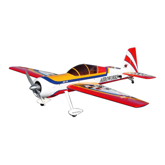
- Page 1 75cc YAK-54 ARF-QB (Quick Build) ASSEMBLY MANUAL AEROWORKS 401 Laredo St. Unit “D” - Aurora, CO. 80011 www.aero-works.net...
-
Page 2: Table Of Contents
TABLE OF CONTENTS Page Aeroworks Contact Information …………………………………………………………... 3 Introduction ………………………………………………………………………………………. 4 Kit Contents……………………………………………………………………………………… Items Needed To Complete ……………………………………………………………………… 7 Tightening and Re-shrinking the Covering / Check all Seams and overlaps for good seal… Wing Assembly………………………………………………………………….………………… 9 Stab and Elevator Assembly……………………………………………………………………... -
Page 3: Aeroworks Contact Information
Further, Aeroworks reserves the right to change or modify this warranty without notice. In that Aeroworks has no control over the final assembly or materials used for final as- sembly, No liability shall be assumed nor accepted for any damage resulting from the use by the user of the final user-assembled product. -
Page 4: Introduction
INTRODUCTION Your new 75cc YAK-54 ARF-QB is a highly aerobatic airplane. It is capable of both preci- sion and 3-D maneuvers. The aircraft builds easily, quickly, and precisely due to its state of the art CAD design, LASER cut technology, and high quality included hardware. We hope you enjoy building and flying your YAK-54 ARF-QB. -
Page 5: Kit Contents
KIT CONTENTS (1) Antenna Tube installed 75cc YAK-54 ARF-QB (1) Pilot holes pre-drilled for tail wheel assembly Basic Aircraft Parts: Left Wing with Aileron – covered: Fuselage with vertical fin (2) 8-32 blind nuts installed for the wing mounting. – covered,... - Page 6 Rudder with (5) pin point hinges (not glued) – covered (2) 1x1150mm plastic coated pull-pull steel cable. (2) Pilot holes pre drilled for control horns mounting (4) 4-40 Metal R/C links with metal clevises and nuts (4) 3.5x5mm brass pull-pull swaging tubes SUB ASSEMBLIES: (8) AL double control horns (48) T2.6x16mm Phillips head mounting screws...
-
Page 7: Items Needed To Complete
ITEMS NEEDED TO COMPLETE Hardware: • Allen wrenches US and Metric. • Dermel cutting disc and sanding drum tool • Electric drill and selection of bits • Flat head screwdriver • Hobby heat gun • Hobby iron • Masking tape •... -
Page 8: Tightening And Re-Shrinking The Covering / Check All Seams And Overlaps For Good Seal
TIGHTENING AND RE-SHRINKING THE COVERING !Check all Seams and Color overlaps for good seal! 1. Open your kit slowly and take care not to dam- 3. If bubbles persist, use a small pin to punch holes age any parts of the kit. Remove all parts from in the bubble to relieve trapped air and reheat. -
Page 9: Wing Assembly
WING ASSEMBLY Aileron Servo Installation The ailerons have been pre-hinged and glued Attach the 18” extension to the outboard servo to the wing panels and are ready for flight. No lead and secure with safety wire, string, tape, other steps are necessary for hinging. Clear or other method. - Page 10 Draw the 18” servo extension through the Secure the servo connectors with safety wire, wing and pull through the wing root rib. string, tape, or other method. Ensure the con- nectors will not come apart from vibration or light tension. Attach one female end of the Y harness to the Fasten the pull string from the inboard servo inboard servo lead.
- Page 11 Pull the 18” extension from the outboard servo Tuck the excess servo wires inside the wing and the Y harness from the inboard servo out root as shown. of the root rib as shown. Plug the remaining female end of the Y har- Install servo in servo well with the output arm ness into the male end of the 18”...
- Page 12 Remove servo and use a 1/16 bit to drill servo Repeat mounting steps for other servo so that mounting holes. both aileron servos are mounted in bottom of wing as shown. Install servo with servo mounting screws. Aileron Control Linkage Installation 1.
- Page 13 2. From that mark measure 1/2” toward the wing Assemble two pushrod and control horn tip and mark the leading edge of the aileron as assemblies as shown. The ball link goes shown. This mark will be the center of the ai- between the left and right sides of the control leron control horn.
- Page 14 6. Mark the position of the control horn mounting 8. Align the left and right sides of the control horns holes. to the mounting holes and mount using six wood screws as shown. Note: The control horn mounting holes may have been factory drilled for you.
-
Page 15: Stab And Elevator Assembly
STAB AND ELEVATOR ASSEMBLY Feed the servo wire through the pre-cut eleva- Elevator Servo Installation tor servo well and out the root rib of the stab as shown. The elevators have been pre-hinged and glued to the stabs and are ready for flight. No other steps are necessary for hinging. - Page 16 Use a 1/16 bit to drill servo mounting holes. Elevator Control Linkage Installation Assemble two pushrod and control horn as- semblies as shown. The ball link goes be- tween the left and right sides of the control horn sides and is secured with a nylon lock nut.
- Page 17 3. From this mark measure 1/2” toward the stab tip 5. Use a 1/16” bit to drill the control horn mount- and mark the leading edge of the elevator as ing holes. shown. This mark will be the center of the ele- vator control horn.
- Page 18 A 1 1/2” servo arm is recommended to achieve Repeat the above steps for the other stab and full deflection of the elevator bevel. Ensure elevator. the servo does not bind at center or either end point at full deflection. Plug the servo wire into the female end of the 36”...
-
Page 19: Rudder And Tailwheel Assembly
RUDDER AND TAILWHEEL ASSEMBLY Mix epoxy in mixing cup and use a tapered Rudder Installation stick to apply the epoxy inside the pre-drilled holes in the trailing edge of the fin. Apply Gather the rudder, six hinges, epoxy, and ma- epoxy to one side of each hinge and insert the terials as shown. - Page 20 Epoxy the hinges into the fin first and allow epoxy to fully cure. Mix epoxy in mixing cup and use a tapered stick to apply the epoxy inside the pre-drilled holes in the leading edge of the rudder. Apply epoxy on to each hinge. Carefully slide the rudder onto each hinge and against the trailing edge of the fin.
- Page 21 Rudder Control Horn Installation Gather the rudder control horn parts as shown below. 2 ball link assemblies and 2 left and 2 right side control horns. Assemble the ball Gather the rudder control linkage parts shown links between the control horns as shown. below.
-
Page 22: Rudder Servos Installation
4. Center the rudder control horn over the mark and 6. Align the left and right sides of the control horns mark the locations of the control horn mounting to the mounting holes and mount using six wood holes. screws as shown. Note: The control horn mounting holes may have Note: Use thin CA to lock screws in place been factory drilled for you. - Page 23 Attach the Y harness to one of the rudder Pull the servo lead and Y harness up through servo leads and secure with safety wire, string, the forward servo cutout. tape, or other method. Ensure the connectors will not come apart from vibration or light ten- sion.
- Page 24 Push the wires under the rudder servo tray and Install rudder servos with servo screws. install the forward servo. 7. Mark and use a 1/16 bit to drill the rudder servo Rudder Pull-Pull Cable Installation mounting holes. Gather the rudder control linkage parts shown Note: If using a higher Torque (300oz min.) Digital, below.
- Page 25 Feed the rudder cable through the pre installed Insert rudder cable through the brass swage cable exit tube in the tail of the fuse toward the tube, then through the threaded coupler hole, front. Repeat on other side. and back through the brass swage tube as shown.
- Page 26 Tighten the second loop through the brass 9. Build the rudder servo arm couplers as shown. swage tube and crimp the brass tube with a We recommend 4-40 Easy Links and 4-40 wire crimping tool or pliers. Cut off excess cable rods for ease of assembly and adjustment.
- Page 27 Attach the rudder servo coupler assembly to Plug the rudder servo Y harness into the rud- the rudder servos as shown. Do not tighten the der channel of the receiver and power up. easy link set screws until the rudder servos are Turn on transmitter to center rudder servos.
- Page 28 15. To allow easier threading, remove ball links Attach ball link to rudder control horn on both from the rudder control horns. Attach two sides of the rudder. Thread the rudder cable threaded couplers to ball links as shown. through a brass swage tube, then the threaded coupler, and back through the brass swage Thread ball link half way onto threaded coupler tube on both sides.
- Page 29 Tighten the second loop through the brass Hint: If additional crimping is needed a small swage tube as shown. C-Clamp may be used for additional crimping pressure. Crimp the brass tube with a crimping tool or Cut off excess cable as shown. pliers.
- Page 30 A drop of thin CA may be applied to the Attach ball links to rudder control horns on swage tube to help secure the cable both sides with 4-40 socket head bolts and ny- lon safety nuts as shown. Hold the threaded coupler below the cable at- Adjust rudder pull-pull cables to desired ten- tach holes to thread into the ball link as shown.
-
Page 31: Tail Wheel Installation
Tail Wheel Installation 1. Gather the tail wheel parts shown below. Tail wheel strut and 1 leaf spring, 3 tail wheel mounting screws, steering tiller and 2 mounting screws, 2 steering springs. Place tail wheel steering tiller over the pre- drilled holes in the bottom of the rudder. - Page 32 Mount the tail wheel steering tiller using two Mount the tail wheel struts and springs using wood screws. three wood screws. Stack the tail wheel leaf spring on the tail Attach the steering springs on both sides of the wheel strut. Position the tail wheel and leaf- tail wheel to the rudder tiller and tail wheel spring on the bottom of the fuse over the pre tiller.
- Page 33 Use pliers to bend spring wire through the Tail wheel final assembly is complete. tiller holes before applying tension to the springs. Slightly stretch the springs and then bend through the tail wheel tiller while holding tail wheel straight. Use pliers to twist spring ends closed around the tillers after desired tension and direction adjustments are complete.
-
Page 34: Main Landing Gear / Wheel Pants Assembly
MAIN LANDING GEAR / WHEEL PANTS ASSEMBLY Remove the landing gear cover by removing Main Landing Gear Installation the two screws on the lower part of the front former. Gather the landing gear parts as shown below. Landing gear strut, 4 mounting bolts, washers, and lock washers, 2 wheels, 2 axle assemblies, 2 wheel pants and 4 mounting bolts with washers. - Page 35 Assemble the landing gear bolts with lock Use a drop of blue lock-tite on landing gear washer and flat washer. Use a drop of blue cover bolts before attaching the landing gear lock-tite on landing gear bolts before attaching cover. the landing gear.
-
Page 36: Wheel And Wheel Pant Installation
3. Use two wrenches to screw the lock nut on the Wheel And Wheel Pant Installation wheel axle. Gather the 2 wheels, 2 axle assemblies, and 4 Note: Do not tighten axle securely yet. wheel collars as shown. 2. Use a drop of blue lock-tite on the wheel axle Align the flat sides of the axle bolt vertical and before assembly. - Page 37 Slide the wheel pant slot over the flat sides of Now tighten the axle nut against the landing the axle bolt and align the wheel pant with the gear strut with a small wrench while using the wheel pant mounting holes. wheel pant slot to hold the flat sides of the axle bolt in alignment.
- Page 38 Install the inner wheel collar on the axle. Use Slide the lock washer then the flat washer on a drop of blue lock-tite on the wheel collar set the wheel pant mounting bolts. Use blue lock- screw and tighten the wheel collar in place. tite on the bolts before final tightening.
- Page 39 Repeat above steps for other wheel and wheel pant.
-
Page 40: Engine, Throttle, Mufflers, Pipe, Canister, Tank, And Cowl Installation
ENGINE, THROTTLE, MUFFLER, PIPE, CANISTER, TANK, AND COWL INSTALLATION Locate the laser cut engine mounting template Engine Installation that matches the bolt pattern for your engine. The 75cc YAK-54 will accept a wide range of engine types. The ZDZ 70/80 and the 3W-75 rear and side carburetor engines with Pitts style mufflers, canisters, and pipes were mounted. - Page 41 Mark the location of the engine mounting Line up the template with the firewall thrust holes on the template. lines and mark the location of the engine mounting holes onto the firewall. Use a 1/4 drill to drill the engine mounting It is recommended to center punch the location holes in the template.
- Page 42 Use a 1/4 drill to drill the engine mounting Insert the carburetor mount through the hole in holes. the firewall and check for proper clearance. 10. Remove the rear mounted carburetor from the If necessary, mark and use a rotary sanding engine.
- Page 43 Recheck for proper clearance. Make sure the Securely tighten the engine to the firewall as firewall does not contact the engine carburetor shown. We recommend using 1/4-20 bolts mount. and lock nuts for engine mounting. You may also use blind nuts behind the firewall for en- gine mounting.
- Page 44 Re-install the engine carburetor behind the 19. 3W-75i rear carburetor engine with Pitts style firewall as shown and secure in place. muffler installed. Note: there is no requirement to modify the engine box for muffler clearance. Typical rear carburetor engine installation with 20.
- Page 45 ZDZ-80 super rear carburetor with Pitts style The following illustrations are for the 3W-75i muffler shown installed. US side mounted carburetor or similar style engines. ZDZ-80 super rear carburetor engine with Pitts 2. Locate the laser cut engine mounting template style muffler installed.
- Page 46 Align the engine thrust lines to the template Use a 1/4 drill to drill the engine mounting thrust lines as shown. holes in the template. Mark the location of the engine mounting Line up the template with the firewall thrust holes on the template.
- Page 47 It is recommended to center punch the location Remove the engine back plate mounting of the engine mounting holes prior to drilling. screws and re-install using locktite. Use a 1/4 drill to drill the engine mounting Use the provided spacers to make the front of holes.
- Page 48 Mount the engine using the engine manufac- Typical side carburetor engine installation be- turer recommended bolts (not supplied) and fore re-installing muffler. locktite. 12. Securely tighten the engine to the firewall as Typical Pitts style muffler for your engine. shown. We recommend using 1/4-20 bolts and lock nuts for engine mounting.
- Page 49 Install Pitts style muffler using lock-tite as 17. 3W-75iUS side carburetor engine with Pitts style shown. muffler installed. Note: there is no requirement to modify the engine box for muffler clearance Securely tighten the muffler to the engine cyl- inder as shown.
- Page 50 Pipe or Canister Muffler Installation Canister Tunnel Preparation 1. The 75cc YAK-54 can accept either a tuned pipe or canister muffler installation. Gather the pipe Iron the bottom covering to ensure it is tight or canister muffler parts of your choice as shown and well sealed to the wood.
- Page 51 Transfer this distance to the bottom of the fuse Draw a line across the fuse belly on the mark starting from the center of the engine cylinder location as shown. This will be the location of head. the rear former of the canister tunnel. Dry fit the header and canister to the bottom of Use a hobby knife to remove the covering the fuse and ensure there is one inch of space...
- Page 52 Use a hobby knife to remove the covering Use a razor saw to remove the front former from the rear of the landing gear cross brace to cross brace across the canister tunnel. the mark between the two bottom fuse string- ers.
- Page 53 Cross braces removed from canister tunnel. Locate the pre-painted balsa canister tunnel rear former as shown below. Dry fit the header and canister inside the tun- Dry fit the canister tunnel rear former inside nel and ensure there is clearance on all sides the rear of the canister tunnel.
- Page 54 Mark the bottom of the fuse line on the former Apply thick CA glue to the top of the canister and mark the top of the canister tunnel where tunnel former. Insert the former into the tun- the former makes contact. nel and press in place.
-
Page 55: Canister Installation
Mark the centerline of the plywood canister Canister Installation mounting bracket. Determine the location of the rear canister mounting hanger. This should be approxi- mately two thirds back on the canister or as described in the canister installation instruc- tions and as desired by the builder. Mark this location on the edge of the canister tunnel. - Page 56 Use a 1/8” bit to drill the canister mounting Use a hobby knife to cut the flat silicon rubber bracket mounting holes. to match the size of the canister mounting bracket. Trace the shape of the canister mounting Locate the pre-drilled counter sunk holes in bracket on the piece of flat silicon as shown.
- Page 57 Place the flat washers inside the counter sunk Apply thick CA glue to the scuffed side of the holes as shown. Ensure the washer is fully silicon rubber piece. seated inside the counter sunk holes. Use a small piece of medium sand paper to Glue the silicon rubber piece on top of the scuff one side of the silicon rubber to ensure a counter sunk holes on the plywood canister...
- Page 58 After the CA glue has fully cured, use a hobby Locate the nylon tie canister mounting strap knife to cut two small round holes in the sili- and the silicon rubber tubing as shown below con rubber. The holes should be just large enough to allow the heads of the canister mounting bolts to pass through the silicon rub- ber and seat against the washers inside.
- Page 59 After splitting the silicon tubing cut off one Slide the silicon tubing onto the nylon tie as side of the split section as shown. This will shown to form the canister strap assembly. provide a relief section of the tubing for the nylon tie lock and insulate it from the metal canister surface.
- Page 60 Slide the pipe mounting doublers under the Use a drop of thick CA to TACK glue the fuel tank floor. It will be necessary to insert pipe mounting doublers in place. the doublers in the lightening hole in the motor box first, then slide under the fuel tank floor.
- Page 61 Place the canister mounting bracket over the After the canister strap is installed use thin CA canister mounting strap. to securely glue the pipe mounting doublers in place. Place a drop of blue locktite on each canister Cinch the nylon tie around the canister tube mounting bolt.
-
Page 62: Tuned Pipe Installation
Make sure the silicon tubing is underneath the Tuned Pipe Installation nylon tie and the nylon tie does not touch the canister pipe. Gather the header and tuned pipe parts as shown below. 1 header, Teflon coupler, 2 steal clamps, and tuned pipe assembly. Bottom view of the final canister muffler in- Iron the bottom covering to ensure it is tight stallation. - Page 63 Remove the covering from the inside edges of Use a razor saw to remove the front former the pipe tunnel. cross brace across the pipe tunnel. Remove the covering from the landing gear Use a razor saw to remove the cross braces cross brace to the pre-installed rear tuned pipe just behind the landing gear from the tuned former and from the front former to the front...
- Page 64 Iron the bottom covering to securely seal the Tuned Pipe Installation covering to the bottom of the rear tuned pipe tunnel former. Determine the location of the rear tuned pipe mounting hanger. This should be approxi- mately two thirds back on the pipe or as de- scribed in the pipe installation instructions and as desired by the builder.
- Page 65 Mark the centerline of the plywood pipe Mark the location of the pipe bracket mount- mounting bracket. ing holes Align the centerline of the plywood bracket Use a 1/8” bit to drill the pipe mounting with the mounting location previously marked bracket mounting holes.
- Page 66 Trace the shape of the pipe mounting bracket Locate the pre-drilled counter sunk holes in on the piece of flat silicon as shown. the plywood pipe mounting bracket and the two flat washers as shown below.. Use a hobby knife to cut the flat silicon rubber Place the flat washers inside the counter sunk to match the size of the pipe mounting bracket.
- Page 67 Use a small piece of medium sand paper to Glue the silicon rubber piece on top of the scuff one side of the silicon rubber to ensure a counter sunk holes on the plywood pipe good glue bond. mounting bracket. This will seal the washers inside the pipe bracket mount as shown.
- Page 68 Insert the pipe mounting bolts through the Use a pair of scissors to split one end of the holes in the pipe mounting bracket as shown. silicon tubing in half approximately 3/4” deep as shown. Locate the nylon tie pipe mounting strap and After splitting the silicon tubing cut off one the silicon rubber tubing as shown below.
- Page 69 Prepare to slide the silicon tubing onto the ny- Locate the two plywood pipe mounting doub- lon tie. The split end of the tubing goes oppo- lers with pre-installed blind nuts as shown. site the nylon tie lock a shown. Slide the silicon tubing onto the nylon tie as Slide the pipe mounting doublers under the shown to form the pipe strap assembly.
- Page 70 Use a drop of thick CA to tack glue the pipe Place the canister mounting bracket over the mounting doublers in place. canister mounting strap. Place the canister strap assembly in the canis- Place a drop of blue locktite on each canister ter tunnel as shown.
- Page 71 Tighten the mounting bolts securely. Cinch the nylon tie around the canister tube and tighten securely. Ensure that the nylon tie does not touch the metal surface of the canister tube and is properly insulated by the silicon tubing as shown below. After the canister strap is installed use thick or Cut off excess tie as shown.
-
Page 72: Cowl Installation
Bottom view of the final tuned pipe installa- Mark the center of the template as shown be- tion. low. Cowl Installation 1. Gather the following material for making a cowl cutout template. Hobby Knife, Ruler, Tape, Felt tip pen or marker Use a large envelope or cardboard file folder for template material. - Page 73 Measure and mark a line 3/16” from the edge Mark a line 3/16” behind the front former on of the template. This will allow for the over- each side of the pipe tunnel. hang of the cowling to the front former. Template after marking.
- Page 74 Align the edge of the template 3/16” behind Lift the template up toward the engine and the front former as shown. trace the outline of the cylinder on the tem- plate as shown. Tape the template in position as shown. Remove the template and cut out the cylinder head tracing as shown.
- Page 75 Mark the bottom center of the cowl as shown. Slide the template aft so that the line on the template is aligned with the aft edge of the cowl. Ensure the centerlines are still aligned. Tape the template in place on the bottom of the cowl.
- Page 76 Trace the cylinder head opening on the bottom Attach the cowl and dry fit. Cut, and sand as of the cowl. necessary until an exact fit is achieved and the cowl does not contact the engine cylinder head. This is a typical cowl cut out with canis- ter or tuned pipe installation.
-
Page 77: Throttle And Choke Servo Installation
Side view of typical Pitts style muffler instal- 2. Gather Soldering Iron, and your choice of sol- lation. der. We recommend using Sta-Brite Silver Solder Throttle and Choke servo Installation Cut 4-40 rod to correct length. 1. Gather the pre-assembled plywood choke and throttle servo mounting trays, the choke and throttle servos, and pushrod parts as shown be- low. - Page 78 Solder threaded coupler to unthreaded end of Typical servo installation for rear carburetor metal 4-40 rod engine. The exact servo installation will de- pend on the engine used. 5. Completed servo pushrod shown below...
-
Page 79: Fuel Tank Assembly
Shown below is an alternative way to make Typical servo installation for rear carburetor the throttle and choke servo push rod. engine. The exact servo installation will de- This method does not require any soldering. pend on the engine used. Align the servo tray However, does require an additional Ball link so there is no binding on the pushrods. -
Page 80: Fuel Tank Installation
Assemble the fuel tank as shown below. Fuel Tank Installation Secure the fuel tubing with nylon ties to the pick-up tube and clunk. 1. Gather the fuel tank parts as shown below. Fuel tank, fuel tubing, and foam rubber, fuel T and fuel dot, nylon ties. - Page 81 Install the fuel tank with foam rubber under- Connect the fuel line to the engine carburetor neath as shown. Cinch the nylon ties securely intake nipple. Drill a fuel vent line hole in to hold the tank against the foam on the fuel the bottom of the engine box floor to allow tank floor.
-
Page 82: Ignition Installation
Install the fuel filling dot as desired on the side Locate the plywood ignition mounting bracket of the fuse. Do not allow the fuel dot to as shown. interfere with the leading edge of the wing. Note: The higher you mount the fuel fill dot the less fuel will siphon out when fueling. - Page 83 Position the engine ignition on the mounting Roll the supplied foam rubber to make a 4 bracket and mark the location of the nylon tie layer pad as shown. holes as shown. Use a 1/8” drill bit to drill the ignition mount- Cut off excess foam to make the pad slightly ing holes.
- Page 84 Mount the engine ignition module using nylon ties and the foam rubber as shown Route the ignition wire to the engine as shown and secure with nylon ties as necessary.
-
Page 85: Radio Installation
RADIO INSTALLATION Gather the switches and mounting hardware to Mark location for switches using switch tem- be used. We used two switches, one for re- plate. Use a modeling knife to cut out the ceiver battery, and one for ignition battery. switch holes. - Page 86 Slide switch wires inside fuse through the Mount ignition regulator as desired. switch cutout. Mount switches in accordance with the switch Mount the ignition battery as desired using the instructions and hardware. radio tray cutouts.
- Page 87 Gather the receiver, battery, regulator, switch Remove the wood plug as shown. and mounting Velcro as shown below Mark location for switch using switch tem- Slide switch wires inside fuse through the plate. Use a modeling knife to cut out the switch cutout.
- Page 88 Mount switches in accordance with the switch Mount the receiver battery as desired using the instructions and hardware. radio tray cutouts. Mount receiver regulator as desired. Mount the receiver as desired using the radio tray cutouts.
- Page 89 Slide receiver antenna under the rudder servo 19. Attach all servos, battery, regulator, and switch tray toward the rear of the fuse. leads to the proper connectors. A typical radio installation is shown below. Push receiver antenna all the way into the re- ceiver antenna tube aft of the rudder servo tray.
-
Page 90: Preflight Preparation
PRE-FLIGHT PREPARATION 1. Gather the 4 wing mounting bolts and 4 #8 large Gather the 4 stab mounting bolts and 4 #6 rubber backed washers. small rubber backed washers. Always check for good fit of the wing attachment bolts. We recommend using cotter pins through the aluminum anti-rotation dowels for a second method of security. - Page 91 5. Gather the 6 cowl mounting bolts and 6 #6 small Gather the 4 hatch mounting bolts and 4 #6 rubber backed washers. small rubber backed washers. Note: Only 4 mounting bolts and washers are shown below. You will use 6 bolts and washers to mount the cowling Mount the cowl using the cowl mounting bolts Slide the rubber backed washers on the hatch...
- Page 92 Finishing 3. Factory placement of decals. 1. Decals supplied with the kit may vary from the photos below. Cut the pre printed adhesive backed decals from the decal sheet and apply where desired. Clean the model surface with alcohol to allow a good bond to the surface. The decals may be applied using Windex or a solu- tion of 1 drop of dish detergent to a cup of water sprayed on the model to assist in proper posi-...
-
Page 93: Center Of Gravity
Center of Gravity Warning, do not skip this step! 3. Start at recommended CG until you are comfort- 3 1/2” 1) The recommended CG is back from the able with the flight characteristics of the aircraft. wing leading edge at the wing tip as shown. You may find this a bit nose heavy at first but that is fine to start with. - Page 94 3. Elevator throw measured in inches at widest Use the supplied flight control deflection me- point of the elevator. . Locate ter to measure the throws in degrees the meter as shown. 4. Rudder throw measured in inches. Elevator throw measured in degrees. Locate throw meter at widest point of the elevator.
-
Page 95: Control Throw Deflection Table
Control Throw Deflection Table Preflight Checks Low Rate High Rate Center of Gravity: Check CG is set properly. Aileron 1 3/4” or 18˚ up 2 3/4” or 30˚ up 1 3/4” or 18˚ down 2 3/4” or 30˚ down Engine: The engine should run smoothly at all throttle settings with smooth transition from Rudder 4”... - Page 96 Spins upright and inverted • Flat Spins upright and inverted • Harriers upright and inverted • Water falls • Torque Rolls • Rolling circles • Rolling harrier The sky and your imagination are you only limits. FLY and ENJOY! AEROWORKS World Class Aircraft...
- Page 97 Yak-54 CUSTOMER NOTES ___________________________________________________________________________ ___________________________________________________________________________ ___________________________________________________________________________ ___________________________________________________________________________ ___________________________________________________________________________ ___________________________________________________________________________ ___________________________________________________________________________ ___________________________________________________________________________ ___________________________________________________________________________ ___________________________________________________________________________ ___________________________________________________________________________ ___________________________________________________________________________ ___________________________________________________________________________ ___________________________________________________________________________ ___________________________________________________________________________ ___________________________________________________________________________ ___________________________________________________________________________ ___________________________________________________________________________ ___________________________________________________________________________ ___________________________________________________________________________ __________________________________________________________________________...
Need help?
Do you have a question about the 75cc YAK-54 ARF-QB and is the answer not in the manual?
Questions and answers